Page 2318 of 2490

Installation
1.
Position motor in housing and fi t and tighten securing nuts and
bolts.
2. Apply suitable lubricant to bore of new spindle inner seal and
fit seal over motor spindle.
3. Holding the capillary and purge valve clear, position
motor/housing assembly on bulkhead.
4. Seat motor spindle seal correctly in upper plenum aperture and
ensure that housing lo cates on lower studs.
5. Fit and tighten the housin g upper securing bolts.
6. Fit and tighten the housing lower securing screws and slide
locking clips inwards.
7. Position throttle cable adjustment bracket on throttle body and
fit and tighten securing bolts.
8. Position purge valve bracket at bulkhead and fit and tighten
securing bolt and nuts.
9. Position engine harness multiplu g on mounting bracket and fit
and tighten securing nut.
10. Connect motor harness multiplug and locate in retaining clip.
11. Apply suitable lubricant to bore of new outer seal and fit with
washer to motor spindle.
12. Fit and fully tighten collar nut on motor spindle.
13. Fit plenum cover. Refer to 76.10.01.
14. Fit wiper arm and blade. Refer to 84.15.44.90.
15. Fit top covers to LH and RH bulkheads and rear of engine
compartment. refer to 76.11.33 and 76.11.35.
16. Fit ground cable to battery te rminal and cover to battery.
Refer to 86.15.15.
Page 2320 of 2490

Installation
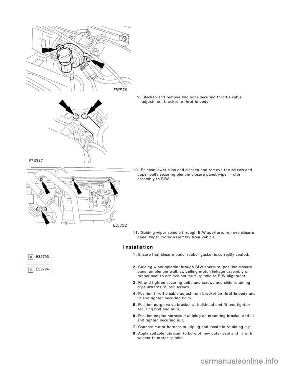
9. Slacken and remove two bolts securing throttle cable
adjustment bracket to throttle body.
10. Release lower clips and slacken and remove the screws and
upper bolts securing plenum closure panel/wiper motor
assembly to BIW.
11. Guiding wiper spindle through BIW aperture, remove closure
panel/wiper motor assembly from vehicle.
E357931. Ensure that closure panel rubbe r gasket is correctly seated.
E357942. Guiding wiper spindle through BI W aperture, position closure
panel on plenum wall, swivelling motor/linkage assembly on
rubber seat to achieve optimu m spindle to BIW alignment.
3. Fit and tighten securing bolts and screws and slide retaining
clips inwards to lock screws.
4. Position throttle cable adjustment bracket on throttle body and
fit and tighten securing bolts.
5. Position purge valve bracket at bulkhead and fit and tighten
securing bolt and nuts.
6. Position engine harness multiplu g on mounting bracket and fit
and tighten securing nut.
7. Connect motor harness multiplug and locate in retaining clip.
8. Apply suitable lubricant to bore of new outer seal and fit with
washer to motor spindle.
Page 2332 of 2490

Roof Opening Panel - Roof Opening Panel Frame
Removal and Installation
Removal
1. Adjust front passenger seat fu lly rearwards and fully recline
seat squab.
2. Remove battery cover and disc onnect ground cable from
battery terminal. Refer to 86.15.19.
3. Remove sliding roof flange finisher. Refer to 76.82.23.
4. Remove sliding roof trim panel. Refer to 76.82.19.
5. Remove grab handles. Refer to 501-05.
6. Remove roof console. Refer to 76.13.69.90.
7. Remove sun visors. Refer to 501-05.
8. Remove cantrail/upper A post trims. Refer to 76.13.20.
9. Remove rear quarter trim s. Refer to 76.13.13.
10. Remove front half headlining for access. refer to 76.64.15.90.
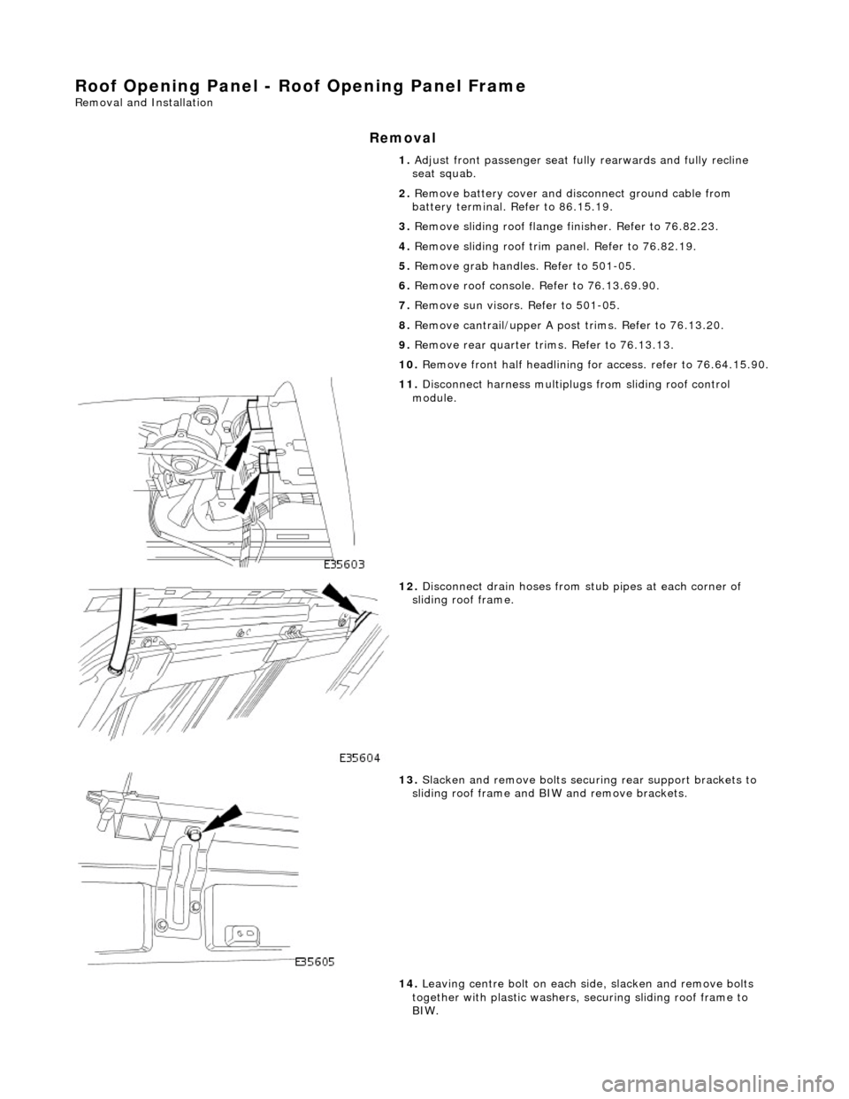
11. Disconnect harness multiplugs from sliding roof control
module.
12. Disconnect drain hoses from stub pipes at each corner of
sliding roof frame.
13. Slacken and remove bolts securi ng rear support brackets to
sliding roof frame and BIW and remove brackets.
14. Leaving centre bolt on each side, slacken and remove bolts
together with plastic washers, securing sliding roof frame to
BIW.
Page 2334 of 2490
tighten securing bolts.
7.
Align rear support brackets and tighten securing bolts.
8. Connect drain hoses to sliding roof frame stub pipes.
9. Fit headlining. Refer to 76.64.15.90.
10. Fit rear quarter trims. Refer to 76.13.13.
11. Fit cantrail/upper A post trims. Refer to 76.13.20.
12. Fit sun visors. Refer to 501-05.
13. Fit roof console. Refer to 76.13.69.90.
14. Fit grab handles. Refer to 501-05.
15. Fit sliding roof trim panel. Refer to 76.82.19.
16. Fit sliding roof flange fi nisher. Refer to 76.82.23.
17. Connect ground cable to batt ery terminal and fit battery
cover. Refer to 86.15.15.
18. Return front passen ger seat to original positions.
Page 2336 of 2490

Installation
1. Synchronise control module gears. Refer to 76.82.48.
2. Exercising care to avoid da maging edge, lower front of
headlining for access.
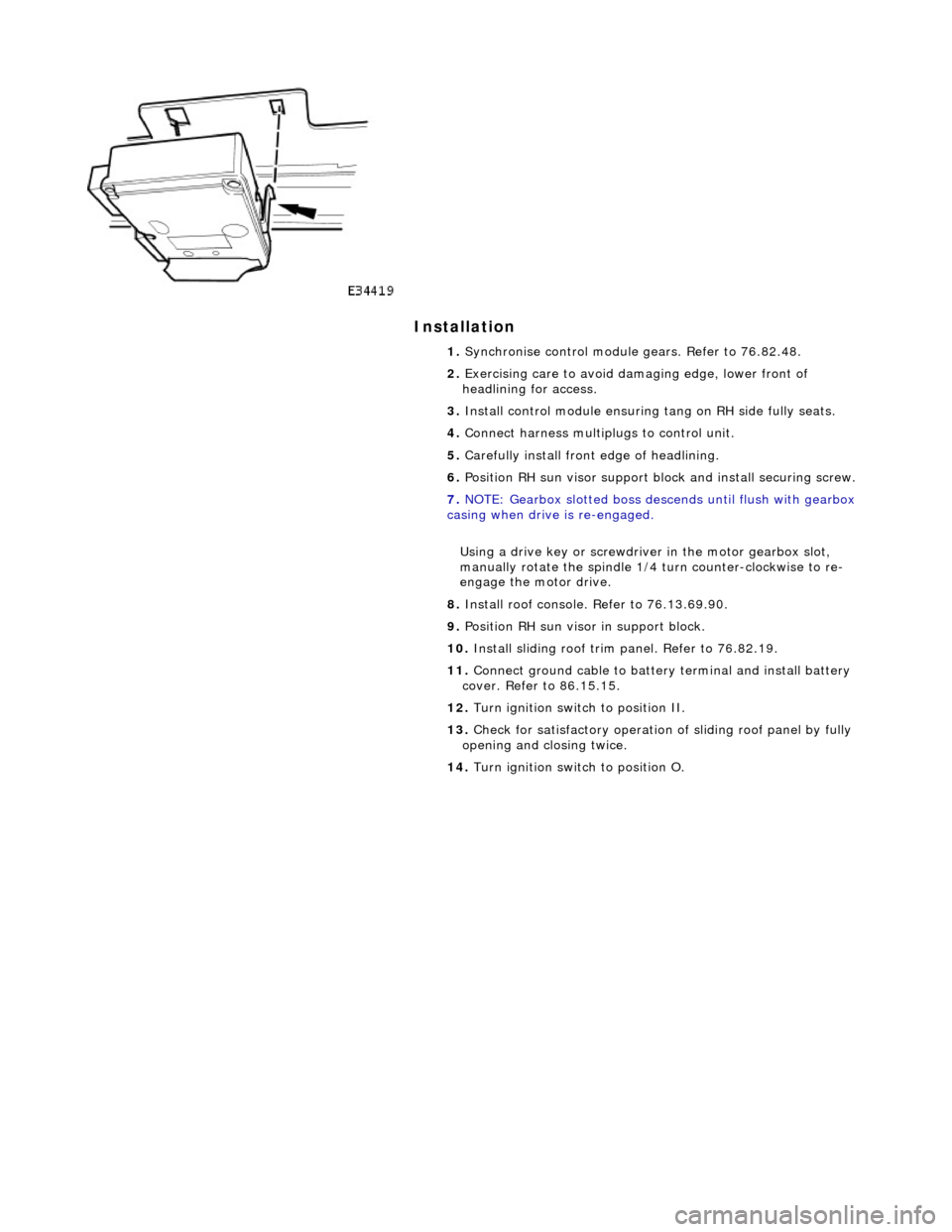
3. Install control module ensuring tang on RH side fully seats.
4. Connect harness multiplugs to control unit.
5. Carefully install front edge of headlining.
6. Position RH sun visor support bl ock and install securing screw.
7. NOTE: Gearbox slotted boss descends until flush with gearbox
casing when drive is re-engaged.
Using a drive key or screwdriver in the motor gearbox slot,
manually rotate the spindle 1/4 turn counter-clockwise to re-
engage the motor drive.
8. Install roof console. Refer to 76.13.69.90.
9. Position RH sun visor in support block.
10. Install sliding roof trim panel. Refer to 76.82.19.
11. Connect ground cable to batter y terminal and install battery
cover. Refer to 86.15.15.
12. Turn ignition switch to position II.
13. Check for satisfactory operation of sliding roof panel by fully
opening and closing twice.
14. Turn ignition switch to position O.
Page 2339 of 2490
Roof Opening Panel - Roof Opening Panel Shield
Removal and Installation
Removal
Installation
1. Turn ignition switch to position II.
2. Open sliding roof to fully tilted position.
3. Turn ignition switch to po sition O and remove key.
4. NOTE: A detent spring is fitt ed at panel front corner for
slider peg engagement.
Pulling trim panel rearwards, release panel front corners from
slider mechanism pegs.
5. Ensure central guide lugs are above mechanism tilt levers.
6. Carefully withdraw trim panel rearwards through roof
aperture.
1. Ensuring central guide lugs are ab ove tilt levers, carefully slide
trim panel into position through roof aperture.
2. Pull trim panel forward and positi on and fully seat front corners
over slider pegs.
3. Connect ground cable to battery terminal and fit battery cover.
Refer to 86.15.15.
4. Insert key and turn ignition switch to position II.
Page 2341 of 2490
Roof Opening Panel - Roof Opening Panel Trim
Removal and Installation
Removal
Installation
1.
Remove sliding roof trim panel for access. Refer to 76.82.19.
2. Turn ignition switch to position II.
3. Fully open sliding roof panel.
4. Turn ignition switch to O and remove key.
5. Remove finisher.
1. Exercising care to avoid damaging edge of headlining,
remove aperture trim finisher from flange.
2. Release headlining from BIW aperture flange.
1. Fit edge of headlining over BIW aperture flange.
2. Fit and fully seat trim finisher to flange.
3. Insert key and turn ig nition switch to II.
4. Close sliding roof panel.
5. Turn ignition switch to O.
6. Fit sliding roof trim panel. Refer to 76.82.19.
Page 2342 of 2490
Roof Opening Panel - Roof Opening Panel Weatherstrip
Removal and Installation
Removal
Installation
1.
Remove sliding roof trim panel for access. Refer to 76.82.19.
2. Remove sliding roof panel fo r access. Refer to 76.82.05.
3. Remove and discard seal fro m roof panel flange and
thoroughly clean flange.
1. Commencing at central rear posi tion, fit and firmly seat new
seal to panel flange.
2. Ensure that the seal is evenly tensioned and free from ripples.
3. Carefully cut off any excess seal and ensure that ends butt
correctly and re main central.
4. Using tool JD 200, crimp seal into position along entire length.
5. Changing commencing position sl ightly, repeat above step to
ensure continuous crimping of seal.
6. Fit sliding roof panel. Refer to 76.82.05.
7. Fit sliding roof trim panel. Refer to 76.82.19.