Page 1054 of 2490

Accessory Drive - Accessory Drive Belt
4.0L SC V8 - AJ26
Re
mo
val and Installation
Remov
a
l
Installation
1.
Op
en the engine compartment and fit paintwork protection
sheets.
2. Remove the supercharger driv e belt, for access. Refer to
operation 18.50.08.
3. Check the belt wear indicator ma rks to confirm that the drive
belt is / is not within limits.
4. CAUTIO
N: When releasing the
belt tension, never apply
any torque in a clockwise direction to the pulley ce ntre bolt (left
hand thread) as it could subsequently loosen.
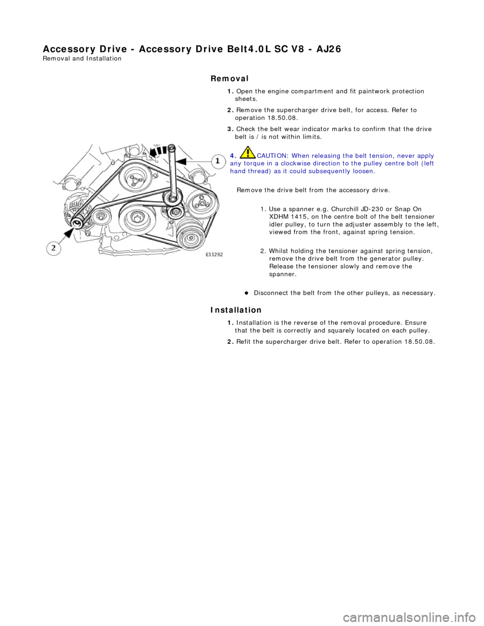
Remove the drive belt fro m the accessory drive.
1. Use a spanner e.g. Churchill JD-230 or Snap On XDHM 1415, on the centre bo lt of the belt tensioner
idler pulley, to turn the adju ster assembly to the left,
viewed from the front, against spring tension.
2. Whilst holding the tensioner against spring tension, remove the drive belt from the generator pulley.
Release the tensioner sl owly and remove the
spanner.
D i
sconnect the belt from the ot
her pulleys, as necessary.
1. Ins
tallation is the
reverse of the remova l procedure. Ensure
that the belt is correctly and sq uarely located on each pulley.
2. Refit the supercharger drive belt. Refer to operation 18.50.08.
Page 1062 of 2490
Starting System - Starting System
Description and Operation
Manufacturer - NipponDenso
Type - RA1.4.
Weight - 3.75 kg (8.27 lb)
Output - 1.4 kW
Rated Time - 30 seconds
Rotation - Clockwise, viewed from pinion end
The starter is of the pre-engaged type; loca ted at the rear left-side of the engine.
When the starter is operated from the key-switch, the engagement lever moves the pinion into mesh with the engine ring
gear teeth, the electrical contacts within the solenoid complete the high power circuit and the starter motor operates to turn
the engine.
Starter Relay
The starter motor control relay is, relay nu mber 5, located inside the engine compartment enclosure (left side of vehicle
RHD and right side of vehicle on LHD).
Page 1071 of 2490
I
nstallation
8.
The u
pper bolt may be removed (a
fter loosening) using a 3/8"
square drive 13 mm socket, ex tensions and U.J as shown.
1. Installation is the reverse of the removal procedure. Tighten
the starter motor securing bolts to 38-48 Nm.
2. Refit the steering rack as detail ed in Operation 57.10.01. Refill
the reservoir with the reco mmended fluid and bleed the
steering system.
3. Lower the ramp. Remove the protection sheets and close the
engine compartment cover.
4. Connect the battery and fit the battery cover.
R
eset the radio informat
ion and the clock.
Page 2
of 2
Page 1095 of 2490

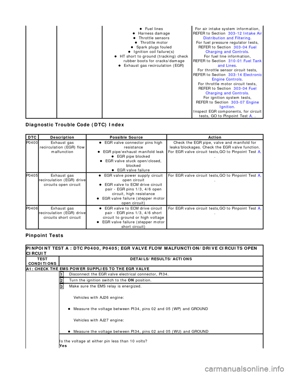
Diagnostic Trouble Code (D
TC) Index
Pinpoint Tests
Fue
l lines
Harness damage
Throttl
e sensors
Throttl
e motor
Spark plugs
fouled
Ignition coil
failure(s)
HT sho
rt to ground (tracking) check
rubber boots for cracks/damage
Exhaus
t gas recirculation (EGR)
F
or air intake syst
em information,
REFER to Section 303
-12
Intake Air
Distribu
tion and Filtering
.
F
or fuel pressure
regulator tests,
REF
ER to Section 303
-04
Fuel
Charging and Con
trols
.
F
or fuel line information,
REFER to Section 310
-01
Fuel Tank
and Lines.
F
or throttle sensor
circuit tests,
REFER to Section 303
-14
Electronic
Engine
Controls
.
Fo
r throttle motor
circuit tests,
REFER to Section 303
-04
Fuel
Charging and Con
trols
.
For ign
ition system tests,
REFER to Section 303
-07
Engine
Ignition.
Inspe
ct EGR components, for circuit
tests, GO to Pinpoint Test A.
.
DT
C
De
scription
Possib
le Source
Acti
on
P0400Exhaus
t gas
recirculation (EGR) flow malfunction
EGR
valve connector pins high
resistance
EGR pipe/exhaust manifold leak EGR pipe block
ed
EGR val
ve stuck open/closed,
blocked
EGR
valve failure
Check the EGR pi
pe, valve and manifold for
leaks/blockages. Check the EGR valve function.
For EGR valve circuit tests,GO to Pinpoint Test A.
.
P0405Exhaus
t gas
recirculation (EGR) drive
circuits open circuit
EGR valve power supply circuit o
pen circuit
EGR valve t
o ECM drive circuit
pair - EGR pins 1/3, 4/6 open circuit, high resistance
EGR val
ve failure (stepper motor
open circuit)
F
or EGR valve circuit tests,GO to Pinpoint Test
A.
.
P0406Exhaus
t gas
recirculation (EGR) drive
circuits short circuit
EGR valve t
o ECM drive circuit
pair - EGR pins 1/3, 4/6 short
circuit to ground or high voltage
EGR val
ve failure (stepper motor
short circuit)
F
or EGR valve circuit tests,GO to Pinpoint Test
A.
.
P
INPOINT TEST A : DTC P0400, P0405; EGR VALV
E FLOW MALFUNCTION/DRIVE CIRCUITS OPEN
CIRCUIT
TE
ST
CONDITIONS
D
ETAILS/RESULTS/ACTIONS
A1: CHECK
THE EMS POWER SU
PPLIES TO THE EGR VALVE
D
isconnect the EGR valve electrical connector, PI34.
1
Turn the ignition swi
tch to the ON
position.
2
Make sure the EMS re lay i
s energized.
Vehicles with AJ26 engine:
Me
asure the voltage between PI34, pins 02 and 05 (WP) and GROUND
Vehicles with AJ27 engine:
Me
asure the voltage between PI34, pins 02 and 05 (WU) and GROUND
3
Is th
e voltage at either pin less than 10 volts?
Yes
Page 1115 of 2490

is at
tached to the three mounting bosses between the V of the cylinder block
has a fil
led for life inte
rnal lubrication system
is po
sitively aligned with the drive
belt by a doweled mounting bracket
C
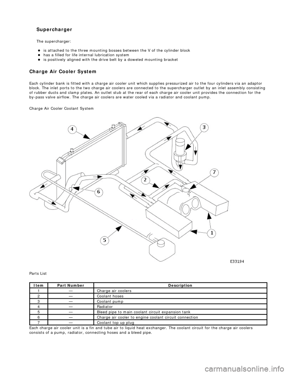
harge Air Cooler System
Each cyl
inder bank is fitted with a charge air cooler unit wh
ich supplies pressurized air to the four cylinders via an adaptor
block. The inlet ports to the tw o charge air coolers are connected to the supercharger outlet by an inle t assembly consisting
of rubber ducts and clamp plates . An outlet stub at the rear of each charge air cooler unit provides the connection for the
by-pass valve airflow. The charge air coolers ar e water cooled via a radiator and coolant pump.
Charge Air Cooler Coolant System
Parts List
Each charge air cooler unit is a fin and tube air to liquid heat exchanger. The coolant circuit for the charge air coolers
consists of a pump, ra diator, connecting hoses and a bleed pipe.
It
em
Par
t Number
De
scription
1—Charge air cool
ers
2—Coo
lant hoses
3—Coo
lant pump
4—Radi
ator
5—Ble
ed pipe to main coolant circuit expansion tank
6—Charge air cooler to en
gine
coolant circuit connection
7—Coo
lant top up plug
Supercharger
The supe
rcharger:
Page 1151 of 2490
The evaporative l
oss flange assembly is fitted to the top of the tank via a seal and locking ring. The assembly is removeable
complete with the fitted components.
The vapour vent / rollover valve is a push fit via a sealing grommet. The fuel pump connector is push fitted and crimped
into a location tube on the underside of the flange.
It
em
Par
t Number
De
scription
1—Vapour vent /
rollover protection valve
2—Fue
l pump connector
3—Evaporative loss flange locking rin
g
Evaporative Flang
e Assembly
Page 1153 of 2490
tank vapou
r pressure.
Canister purge operation is as described in Evaporative Emissions Control.
Evaporative Flange Assembly
The evaporative loss flange assembly is fitted to the top of the tank via a seal and locking ring. The assembly is removeable
complete with the fitted components.
The vapour vent / rollover valve and pressure sensor are a pu sh fit via sealing grommets. The fuel pump connector is push
fitted and crimped into a location tu be on the underside of the flange.
It
em
Par
t Number
De
scription
1—Vapour vent /
rollover protection valve
2—Pres
sure sensor
3—Fue
l pump connector
4—Evaporative loss flange locking rin
g
Page 1157 of 2490

The OR
VR system features are :
N
arrow fuel filler pipe and tank check valve.
Fue
l level vent valve (FLVV) fitted to the evaporative flan
ge and consisting of a two stage shut-off valve with rollover
protection and a pressure relief valve.
Grade ven
t valve with rollover protection, fitted to the ev
aporative flange and with an outlet pipe connected to the
FLVV vapour outlet pipe.
Large bore vapour vent pipes.
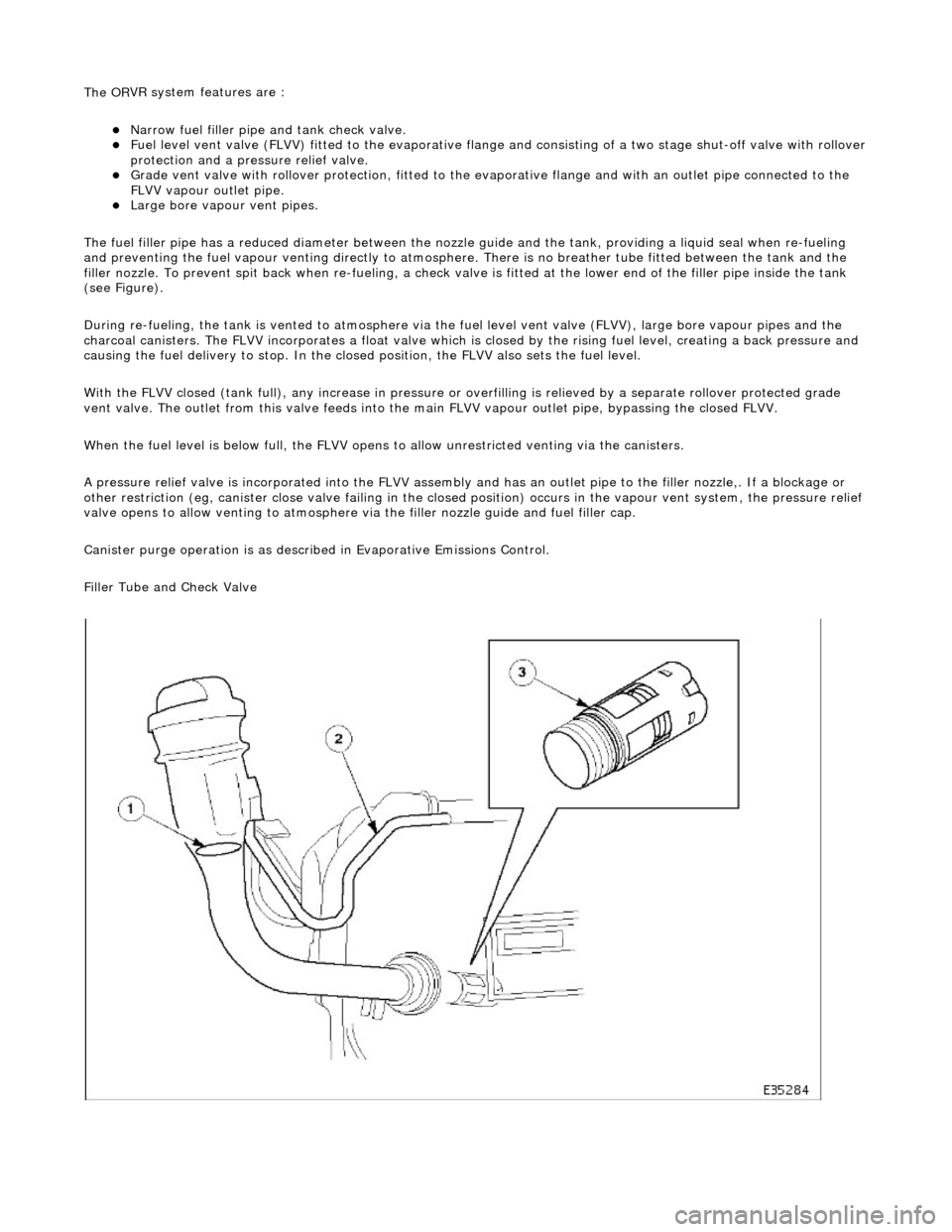
The fuel filler pipe has a reduced diameter between the nozzle guide and the tank, providing a liquid seal when re-fueling
and preventing the fuel vapour venting directly to atmosphere. There is no breather tube fitted between the tank and the
filler nozzle. To prevent spit back when re-fueling, a check valv e is fitted at the lower end of the filler pipe inside the tank
(see Figure).
During re-fueling, the tank is vented to atmosphere via the fuel level vent valv e (FLVV), large bore vapour pipes and the
charcoal canisters. The FLVV incorp orates a float valve which is closed by the rising fuel level, creating a back pressure and
causing the fuel delivery to stop. In the closed position, the FLVV also sets the fuel level.
With the FLVV closed (tank full), any increase in pressure or overfilling is relieved by a separate rollover protected grade
vent valve. The outlet from this valve feeds into the main FLVV vapour outlet pipe, bypassing the closed FLVV.
When the fuel level is below full, the FLVV opens to allow unrestricted venting via the canisters.
A pressure relief valve is incorp orated into the FLVV assembly and has an outlet pipe to the filler nozzle,. If a blockage or
other restriction (eg, canister close valve failing in the closed position) occurs in the vapour vent system, the pressure reli ef
valve opens to allow venting to atmosphere via the filler nozzle guide and fuel filler cap.
Canister purge operation is as described in Evaporative Emissions Control.
Filler Tube and Check Valve