Page 888 of 2490
3. Fit the chain tensioning tool 303 - 532 to the exhaust camshaft
sprocket.
Reposition the sprocket (and the VVT unit) for the most
advantageous position for use of the tool.
Remove the tool.
4. Refit the primary timing chain.
1. Fit the primary chain to position over the crankshaft sprocket and the VVT unit sprocket. There must be no
slack on the drive side of the primary chain.
2. The VVT unit must not be rotated on the camshaft
5. Fit the primary chain tensioner blade.
1. Position the tensioner blade to the cylinder block.
2. Fit the retaining / pivot bolt and tighten it to 12-16 Nm.
6. Refit the primary chain tensione r assembly. Refer to Operation
12.65.54 in this Section.
Use a wedge 303 - 533 (or two if required) between the
primary chain tensioner and te nsioner blade, to take up
the slack in the chain.
Page 889 of 2490

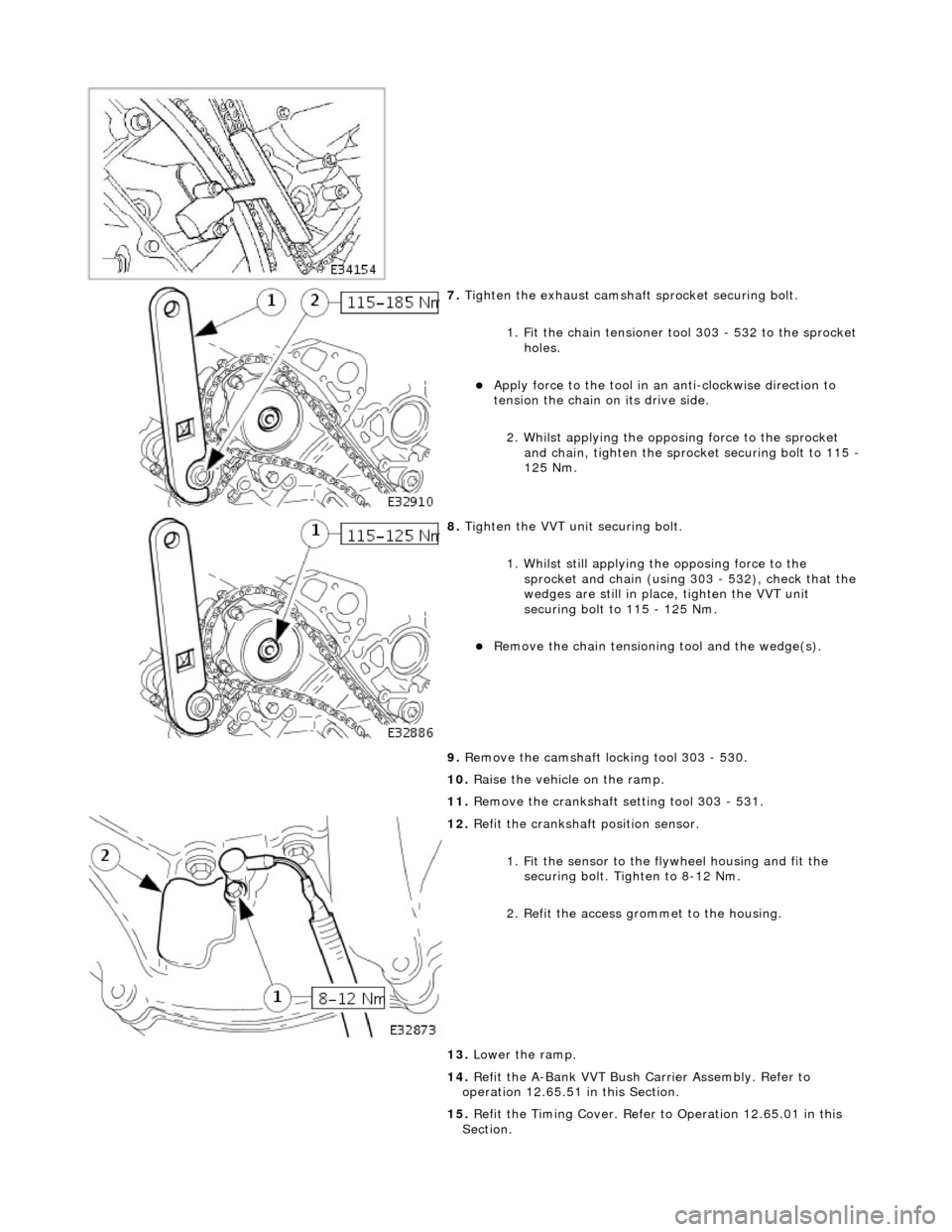
7. Tighten the exhaust camshaft sprocket securing bolt.
1. Fit the chain tensioner tool 303 - 532 to the sprocket holes.
Apply force to the tool in an anti-clockwise direction to
tension the chain on its drive side.
2. Whilst applying the opposing force to the sprocket and chain, tighten the sprock et securing bolt to 115 -
125 Nm.
8. Tighten the VVT unit securing bolt.
1. Whilst still applying the opposing force to the
sprocket and chain (using 303 - 532), check that the
wedges are still in place, tighten the VVT unit
securing bolt to 115 - 125 Nm.
Remove the chain tensioning tool and the wedge(s).
9. Remove the camshaft locking tool 303 - 530.
10. Raise the vehicle on the ramp.
11. Remove the crankshaft setting tool 303 - 531.
12. Refit the crankshaft position sensor.
1. Fit the sensor to the fl ywheel housing and fit the
securing bolt. Tighten to 8-12 Nm.
2. Refit the access grommet to the housing.
13. Lower the ramp.
14. Refit the A-Bank VVT Bush Carrier Assembly. Refer to
operation 12.65.51 in this Section.
15. Refit the Timing Cover. Refer to Operation 12.65.01 in this
Section.
Page 891 of 2490
Engine - Variable Camshaft Timing Oil Control Unit Housing LH
In-vehicle Repair
Removal
Installation
1. Open the engine compartment and fit paintwork protection
sheets.
2. Set the engine compartment cover to the service access
position.
3. Disconnect the batt ery ground cable.
Remove the battery cover.
4. Remove the Timing Co ver. Refer to Operation 12.65.01 in this
Section.
5. Remove the VVT bush carrier.
1. Remove the two bolts and one nut which secure the carrier to the cylinder block.
2. Release the carrier from the two ring dowels and
remove it.
6. Remove the seals from the bush carrier.
1. Remove the sealing ring (scarf jointed) from the
carrier bush groove.
2. Remove the O-ring from the carrier oil-way recess.
7. Clean and inspect all relevant components.
1. Fit new seals to the bush carrier.
1. Fit the new sealing ring (scarf jointed) to the carrier bush groove.
2. Fit a new O-ring to the carrier oil-way.
Page 892 of 2490
2. Fit the bush carrier to the cylinder block.
Lubricate the seal (scarf jointed) and the bush.
1. Fit the bush carrier assembly.
Check that the seals are in pl ace and that the ring dowels
are engaged squarely. Fully locate the assembly as much
as possible by hand pressure.
2. Fit the two securing bolts and one nut. Tighten to 19- 23 Nm.
3. Refit the Timing Cover. Refer to Operation 12.65.01 in this
Section.
4. Move the engine compartment co ver from the service position
and connect the gas struts.
5. Remove the paint protection sheets and close the cover.
6. Connect the battery and fit the battery cover.
Refer to the Battery Reconnection Procedure 86.15.15.
Page 893 of 2490
V
ariable Camshaft Timing Oil Control Unit Housing RH
12.65.51
Removal
1. Open the engine compartment and fit paintwork protection sheets.
2. Set the engine compartment cover to the service access position.
3
. Disconnect the battery ground cable.
Remove the battery cover.
4. Remove the Timing Cover. Refer to Operation <<12.65.01>>
in this Section.
5
. Remove the VVT bush carrier.
1. Remove the three bolts which secure the carrier to the cylinder block.
Page 895 of 2490
2
. Fit the bush carrier to the cylinder block.
Lubricate the seal (scarf jointed) and the bush.
1. Fit the bush carrier assembly.
Check that the seals are in place and that the ring dowels are engaged squarely. Fully locate the
assembly as much as possible by hand pressure. 2. Fit the three securing bolts. Tighten to 19-23 Nm.
3. Refit the Timing Cover. Refer to Operation <<12.65.01>> in this Section.
4. Move the engine compartment cover from the service position and connect the gas struts.
5. Remove the paint protection sheets and close the cover.
6. Connect the battery and fit the battery cover. Refer to the Battery Reconnection Procedure <<86.15.15>>.
Page 907 of 2490

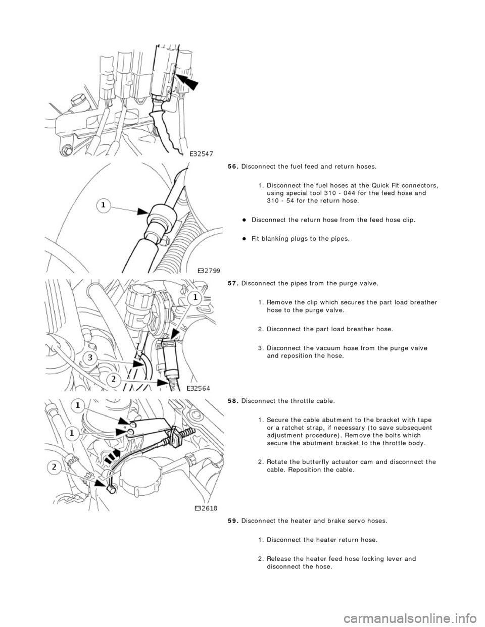
56. Disconnect the fuel feed and return hoses.
1. Disconnect the fuel hoses at the Quick Fit connectors,
using special tool 310 - 044 for the feed hose and
310 - 54 for the return hose.
Disconnect the return hose from the feed hose clip.
Fit blanking plugs to the pipes.
57. Disconnect the pipes from the purge valve.
1. Remove the clip which secu res the part load breather
hose to the purge valve.
2. Disconnect the part load breather hose.
3. Disconnect the vacuum hose from the purge valve and reposition the hose.
58. Disconnect the throttle cable.
1. Secure the cable abutment to the bracket with tape or a ratchet strap, if nece ssary (to save subsequent
adjustment procedure). Remove the bolts which
secure the abutment bracke t to the throttle body.
2. Rotate the butterfly actuator cam and disconnect the cable. Reposition the cable.
59. Disconnect the heater and brake servo hoses.
1. Disconnect the he ater return hose.
2. Release the heater feed hose locking lever and
disconnect the hose.
Page 908 of 2490
3. Disconnect the brake servo hose.
60. Fit engine rear lifting eyes (303 - 536).
61. Traverse the hoist to the engine compartment and lower it to
working height.
62. Fit lifting chains to the hoist and connect to each engine
lifting eye. Use longer chains to the rear lifting eyes to allow
the engine to tilt rearwards wh en removing from the vehicle.
63. Remove the engine front mounting nuts.
64. Raise the ramp.
65. Disconnect the transmission connector.
1. Release the lever lock on the transmission harness
multi-plug.
2. Disconnect the connector.
66. Disconnect the transmission selector cable.