1998 JAGUAR X308 lock
[x] Cancel search: lockPage 1023 of 2490
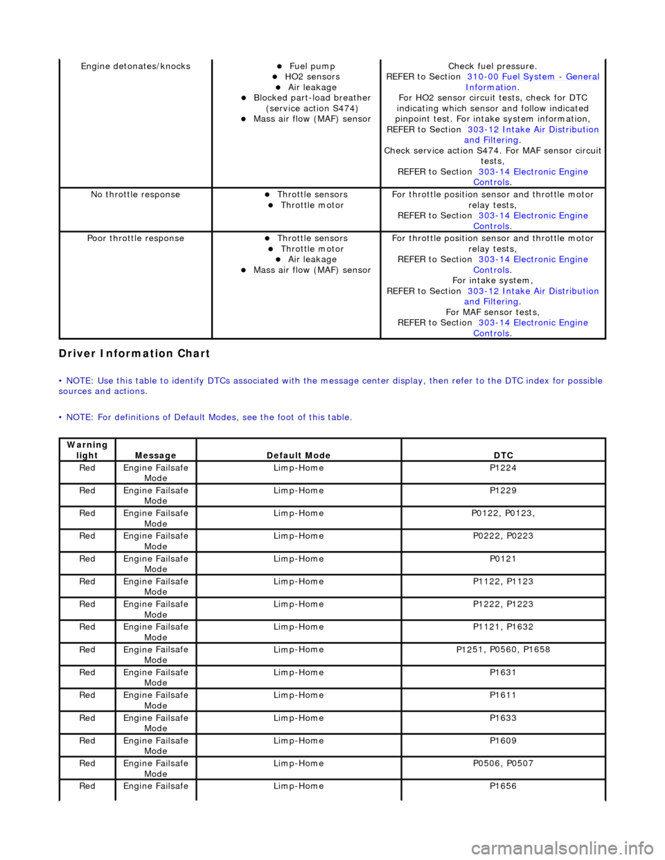
Driver Informa
tion Chart
•
NOTE: Use this table to identify DTCs associated with the me
ssage center display, then refer to the DTC index for possible
sources and actions.
• NOTE: For definitions of Default Modes, see the foot of this table.
Engine deton
ates/knocks
Fue
l pump
HO2 sensors Air leakage Blocked part-load breather
(
service action S474)
Mass ai
r flow (MAF) sensor
Chec
k fuel pressure.
REFER to Section 310
-00
Fuel System
- Gen
eral
Informati
on
.
F
or HO2 sensor circuit
tests, check for DTC
indicating which sensor and follow indicated
pinpoint test. For intake system information,
REFER to Section 303
-1
2 Intake Air Distribution
and F
iltering
.
Check service
action S474. For MAF sensor circuit
tests,
REFER to Section 303
-14 Elec
tronic Engine
Controls.
No
throttle response
Throttl
e sensors
Throttl
e motor
F
or throttle position se
nsor and throttle motor
relay tests,
REFER to Section 303
-14 Elec
tronic Engine
Controls.
Poor throttle responseThrottl
e sensors
Throttl
e motor
Air leakage Mass ai
r flow (MAF) sensor
F
or throttle position se
nsor and throttle motor
relay tests,
REFER to Section 303
-14 Elec
tronic Engine
Controls.
Fo
r intake system,
REFER to Section 303
-1
2 Intake Air Distribution
and F
iltering
.
For MAF
sensor tests,
REFER to Section 303
-14 Elec
tronic Engine
Controls.
Warning
lightMess
age
De
fault Mode
DT
C
Re
d
Engine
Failsafe
Mode
Lim
p-Home
P1224
Re
d
Engine
Failsafe
Mode
Lim
p-Home
P1229
Re
d
Engine
Failsafe
Mode
Lim
p-Home
P01
22, P0123,
Re
d
Engine
Failsafe
Mode
Lim
p-Home
P02
22, P0223
Re
d
Engine
Failsafe
Mode
Lim
p-Home
P0121
Re
d
Engine
Failsafe
Mode
Lim
p-Home
P11
22, P1123
Re
d
Engine
Failsafe
Mode
Lim
p-Home
P12
22, P1223
Re
d
Engine
Failsafe
Mode
Lim
p-Home
P11
21, P1632
Re
d
Engine
Failsafe
Mode
Lim
p-Home
P12
51, P0560, P1658
Re
d
Engine
Failsafe
Mode
Lim
p-Home
P1631
Re
d
Engine
Failsafe
Mode
Lim
p-Home
P1611
Re
d
Engine
Failsafe
Mode
Lim
p-Home
P1633
Re
d
Engine
Failsafe
Mode
Lim
p-Home
P1609
Re
d
Engine
Failsafe
Mode
Lim
p-Home
P05
06, P0507
Re
d
Engine
Failsafe
Lim
p-Home
P1656
Page 1025 of 2490
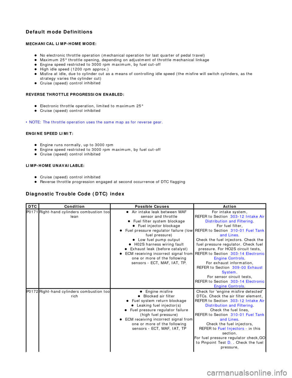
Default mode Definitions
MECH
ANICAL LIMP-HOME MODE:
No el
ectronic throttle operation (mechanical
operation for last quarter of pedal travel)
M
aximum 25° throttle opening,
depending on adjustment of th rottle mechanical linkage
Engine
speed restricted to 3000
rpm maximum, by fuel cut-off
Hi
gh idle speed (1200 rpm approx.)
Misfire
at idle, due to cylinder cut as a means of control
ling idle speed (the misfire will switch cylinders, as the
strategy varies th e cylinder cut)
Cruise (speed) contr
ol inhibited
REVERSE THROTTLE PROGRESSION ENABLED:
El
ectronic throttle operation, limited to maximum 25°
Cruise (speed) contr
ol inhibited
• NOTE: The throttle oper ation uses the same map as for reverse gear.
ENGINE SPEED LIMIT:
Engine
runs normally, up to 3000 rpm
Engine
speed restricted to 3000
rpm maximum, by fuel cut-off
Cruise (speed) contr
ol inhibited
LIMP-HOME UNAVAILABLE:
Cruise (speed) contr
ol inhibited
R
everse throttle pr
ogression engaged at second occurrence of DTC flagging
Diagnostic Trouble Code (D
TC) index
DT
C
Cond
ition
P
ossible Causes
Acti
on
P0171Right-hand cylinders combustion too
leanAir
intake leak between MAF
sensor and throttle
F
uel filter system blockage
F
uel injector blockage
F
uel pressure regulator failure (low
fuel pressure)
Low f
uel pump output
H0
2S harness wiring fault
E
xhaust leak (before catalyst)
ECM receivi
ng incorrect signal from
one or more of the following
sensors - ECT, MAF, IAT, TP.
Fo
r intake system,
REFER to Section 303
-12
Intake Air
Distribu
tion and Filtering
.
F
or fuel filter,
REFER to Section 310
-01
Fuel Tank
and Lines.
Chec
k the fuel injectors. Check the
fuel pressure regu lator. Check fuel
pressure. For HO2S circuit tests,
REFER to Section 303
-14
Electronic
Engine
Controls
.
F
or exhaust information,
REFER to Section 309
-00
Exhaust
Sy
stem
.
For se
nsor circuit tests,
REFER to Section 303
-14
Electronic
Engine
Controls
.
P0172Right-hand cylinders combustion too
ri
ch
Engine
misfire
Bl
ocked air filter
F
uel system return blockage
Leak
ing fuel injector(s)
F
uel pressure regulator failure
(high fuel pressure)
ECM receivi
ng incorrect signal from
one or more of the following sensors - ECT, MAF, IAT, TP
Chec
k for 'engine misfire detected'
DTCs. Check the air filter element,
REFER to Section 303
-12
Intake Air
Distribu
tion and Filtering
.
Chec
k the fuel lines,
REFER to Section 310
-01
Fuel Tank
and Lines.
Chec
k the fuel injectors,
REFER to Fuel Injectors
- in t
his
section.
For fuel pressure regulator check,GO
to Pinpoint Test D.
.
Check the fuel
pressure,
Page 1026 of 2490
REFE
R to Section 310
-00
Fu
el
Sy
ste
m
- General
Information
.
Check f o
r DTCs indicating a sensor
fault,
REFER to Section 303
-14 El
ectronic
Engine
C
ontrols
.
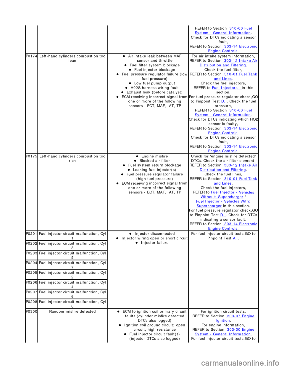
P0174
Left-hand cyl i
nders combustion too
lean
Air in
take leak between MAF
sensor and throttle
F u
el filter system blockage
F
u
el injector blockage
F
u
el pressure regulator failure (low
fuel pressure)
Low f u
el pump output
H0
2S harness wiri
ng fault
E
x
haust leak (before catalyst)
ECM receivi
n
g incorrect signal from
one or more of the following sensors - ECT, MAF, IAT, TP
F o
r air intake sy
stem information,
REFER to Section 303
-12 Int
ake Air
Distribu tion and Filterin
g
.
Check the fuel fi lter,
REF
ER to Section 310
-01
Fu
el Tank
and Lines.
Chec k the
fuel injectors,
REFER to Fuel Injectors
- in t h
is
section.
For fuel pressure regulator check,GO
to Pinpoint Test D.
. Ch
eck the fuel
pressure,
REFER to Section 310
-00 Fu
el
Sy
ste
m
- General
Information
.
Check f o
r DTCs indicating which HO2
sensor is faulty,
REFER to Section 303
-14 El
ectronic
Engine
C
ontrols
.
Check f o
r DTCs indicating a sensor
fault,
REFER to Section 303
-14 El
ectronic
Engine
C
ontrols
.
P0175Left-hand cyli
nders combustion too
rich
Engine m
isfire
Bl
ocked air
filter
F
u
el system return blockage
Leak
i
ng fuel injector(s)
F
u
el pressure regulator failure
(high fuel pressure)
ECM receivi n
g incorrect signal from
one or more of the following sensors - ECT, MAF, IAT, TP
Check for 'en
gine misfire detected'
DTCs. Check the air filter element,
REFER to Section 303
-12 Int
ake Air
Distribu tion and Filterin
g
.
Chec k the
fuel lines,
REFER to Section 310
-01 Fu
el Tank
and Lines.
Chec k the
fuel injectors,
REFER to Fuel Injector
- Vehicles Wi
thout: Supercharger
/
Fue
l Injector
- Ve
hicles With
:
Supercharger
in this
section.
For fuel pressure regulator check,GO
to Pinpoint Test D.
. Check for DT
Cs
indicating a sensor fault,
REFER to Section 303
-14 El
ectronic
Engine
C
ontrols
.
P0201F
u
el injector circuit malfunction, Cyl
1
Injector discon n
ected
Inject
or wir
ing open or short circuit
Injector fail
ure
F
o
r fuel injector circuit tests,GO to
Pinpoint Test A.
.
P0202Fu
el injector circuit malfunction, Cyl
3
P0203F u
el injector circuit malfunction, Cyl
5
P0204F u
el injector circuit malfunction, Cyl
7
P0205Fu
el injector circuit malfunction, Cyl
2
P0206Fu
el injector circuit malfunction, Cyl
4
P0207F u
el injector circuit malfunction, Cyl
6
P0208F u
el injector circuit malfunction, Cyl
8
P0300Ran d
om misfire detected
ECM t
o
ignition coil primary circuit
faults (cylinder misfire detected DTCs also logged)
Ignition coil ground circuit; open
ci
rcuit, high resistance
F
u
el injector circuit fault(s)
(injector DTCs also logged)
F o
r ignition circuit tests,
REFER to Section 303
-07 En
gine
Ignition.
F or engi
ne information,
REFER to Section 303
-00 En
gine
Sy
ste
m
- General
Information
.
F o
r fuel injector circuit tests,GO to
Page 1042 of 2490
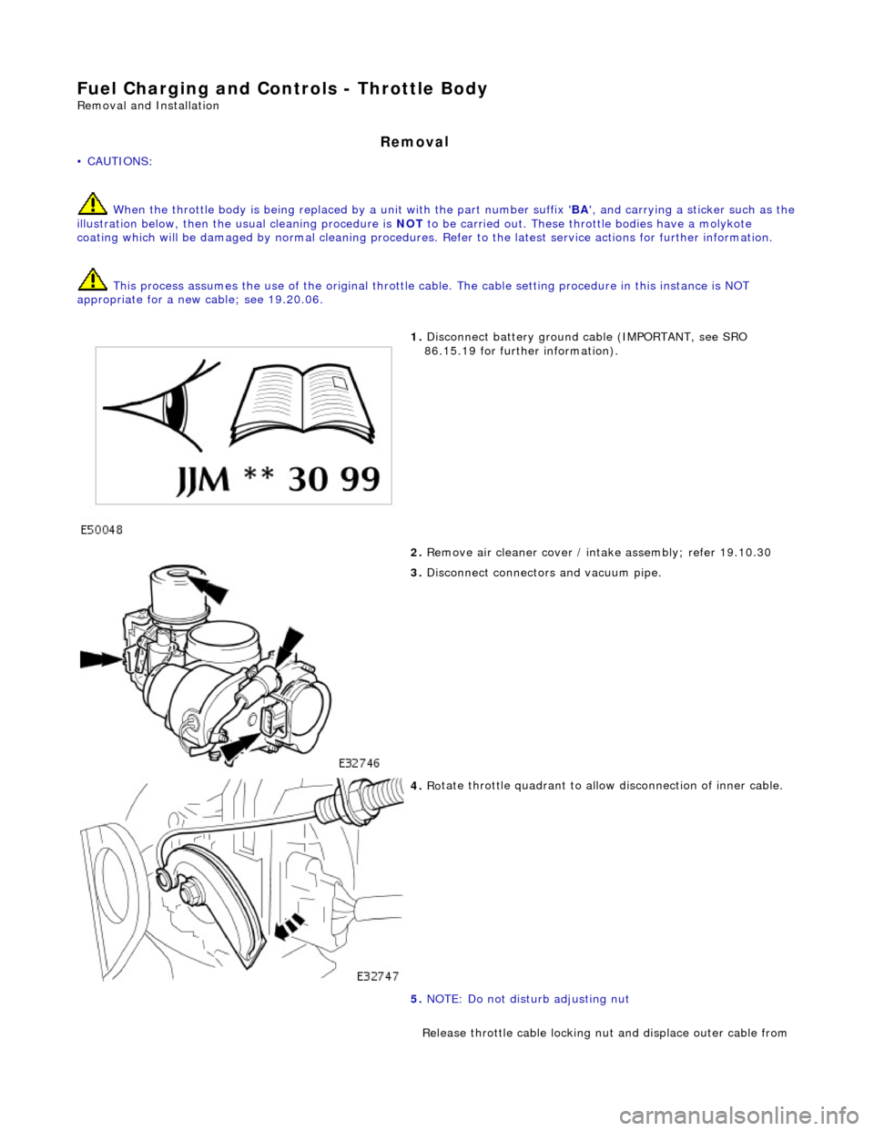
Fuel Char
ging and Controls - Throttle Body
Re
mo
val and Installation
Remov
a
l
• C
A
UTIONS:
When the throttle body is being replaced by a unit with the part number suffix ' BA', and carrying a sticker such as the
illustration below, then the usual cleaning procedure is NOT to be carried out. These thro ttle bodies have a molykote
coating which will be damaged by normal cleaning procedures. Refer to the latest service action s for further information.
This process assumes the use of the original throttle ca ble. The cable setting procedure in this instance is NOT
appropriate for a new cable; see 19.20.06.
1. Disc onne
ct battery ground cable (IMPORTANT, see SRO
86.15.19 for further information).
2. Remove air cleaner cover / in take assembly; refer 19.10.30
3. Disc
onnect connectors and vacuum pipe.
4. Ro
tate throttle quadrant to allow disconnection of inner cable.
5. NOTE: Do not disturb adjusting nut
Release throttle cable locking nut and displace outer cable from
Page 1045 of 2490
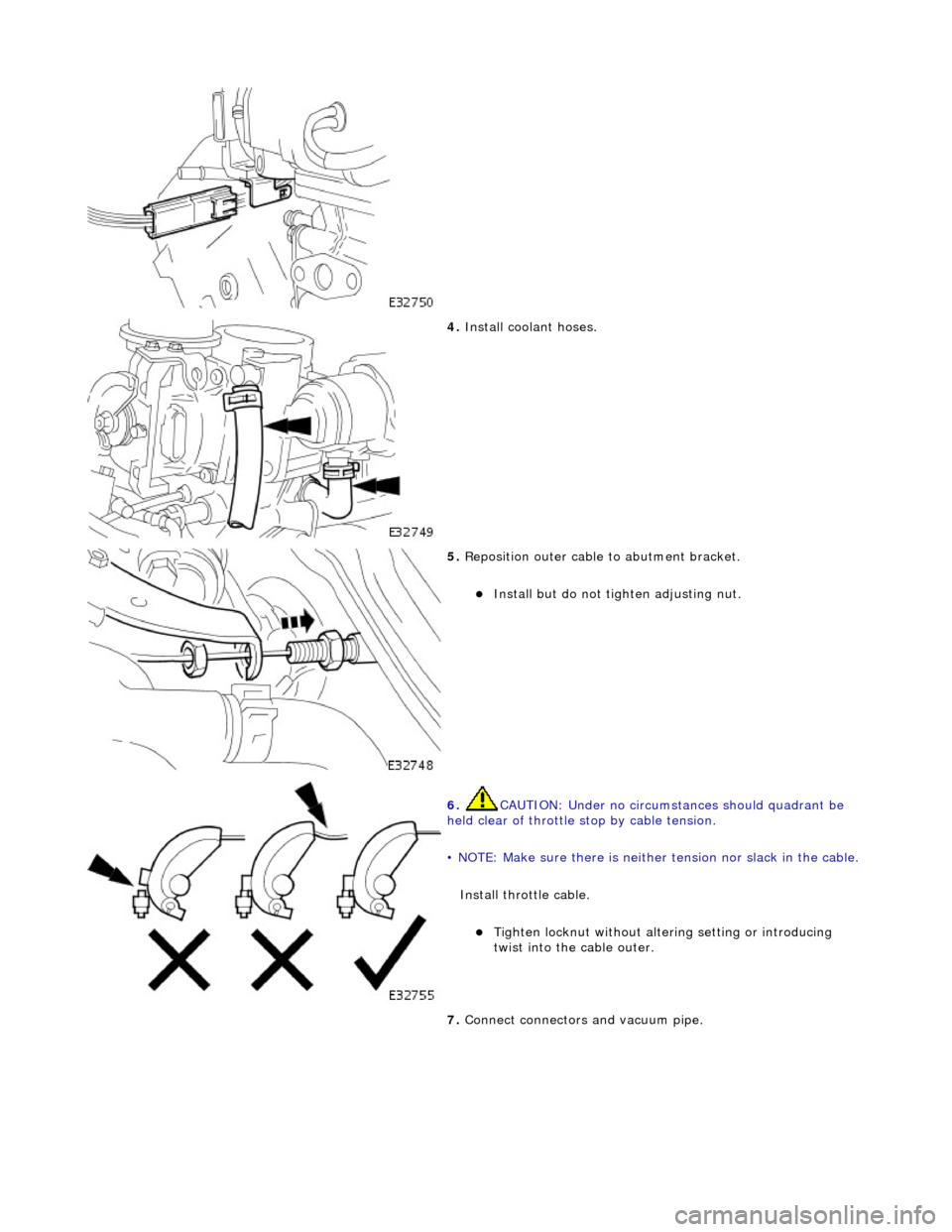
4. Inst
all coolant hoses.
5. R
eposition outer cable
to abutment bracket.
Install but do not tigh
ten adjusting nut.
6. CAUTI
ON: Under no circumst
ances should quadrant be
held clear of throttle stop by cable tension.
• NOTE: Make sure ther e is neither tension nor slack in the cable.
Install throttle cable.
Tigh
ten locknut without altering setting or introducing
twist into the cable outer.
7. Connect conn
ectors and vacuum pipe.
Page 1051 of 2490
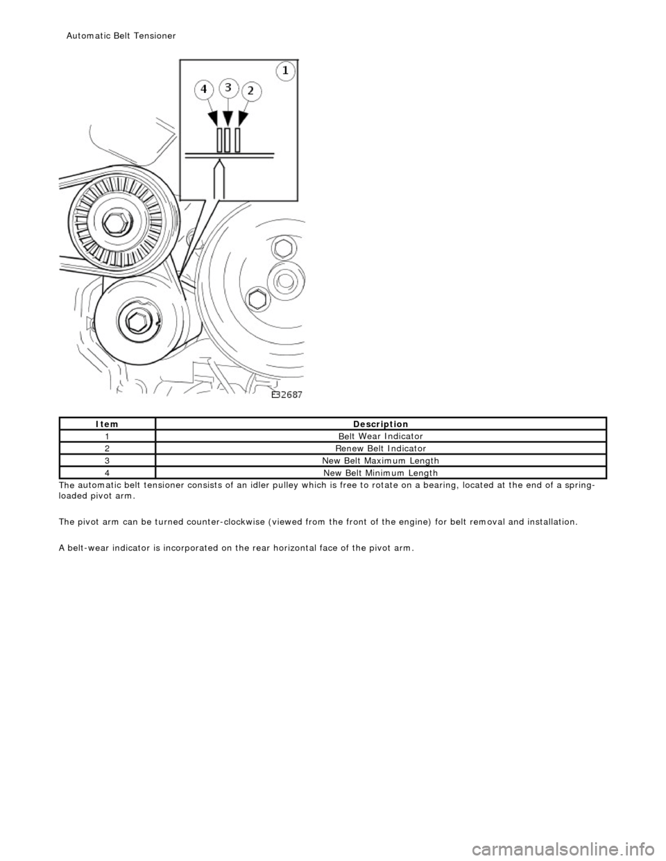
The
automatic belt tensioner consists of an idler pulley which is
free to rotate on a bearing, located at the end of a spring-
loaded pivot arm.
The pivot arm can be turned counter-clockwise (viewed from th e front of the engine) for belt removal and installation.
A belt-wear indicator is incorporated on th e rear horizontal face of the pivot arm.
It
em
De
scription
1Bel
t Wear Indicator
2Re
new Belt Indicator
3N
ew Belt Maximum Length
4N
ew Belt Minimum Length
Au
tomatic Belt Tensioner
Page 1052 of 2490
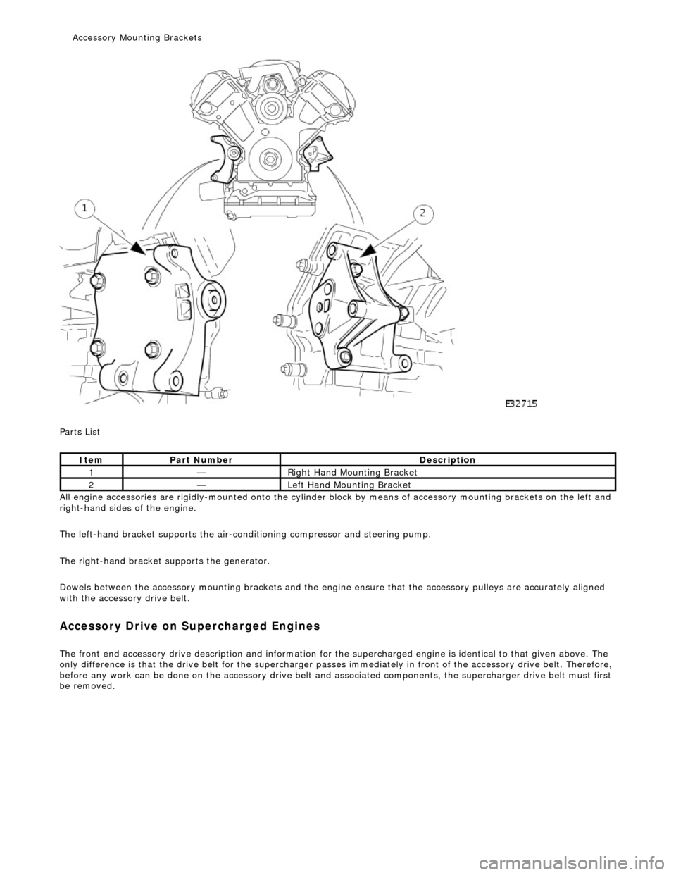
P a
rts List
All engine accessories are rigidly-mounted onto the cylinder block by means of accessory moun ting brackets on the left and
right-hand sides of the engine.
The left-hand bracket supports the air-cond itioning compressor and steering pump.
The right-hand bracket su pports the generator.
Dowels between the accessory mounting br ackets and the engine ensure that the accessory pulleys are accurately aligned
with the accessory drive belt.
A ccess
ory Drive on Supercharged Engines
The front
en
d accessory drive description and information for the
supercharged engine is identical to that given above. The
only difference is that the drive belt for the supercharger passes im mediately in front of the accessory drive belt. Therefore,
before any work can be done on the acce ssory drive belt and associated components, the supercharg er drive belt must first
be removed.
It e
m
Par
t
Number
De
scr
iption
1—R
i
ght Hand Mounting Bracket
2—Left H
and Mounting Bracket
Access
ory Mounting Brackets
Page 1053 of 2490
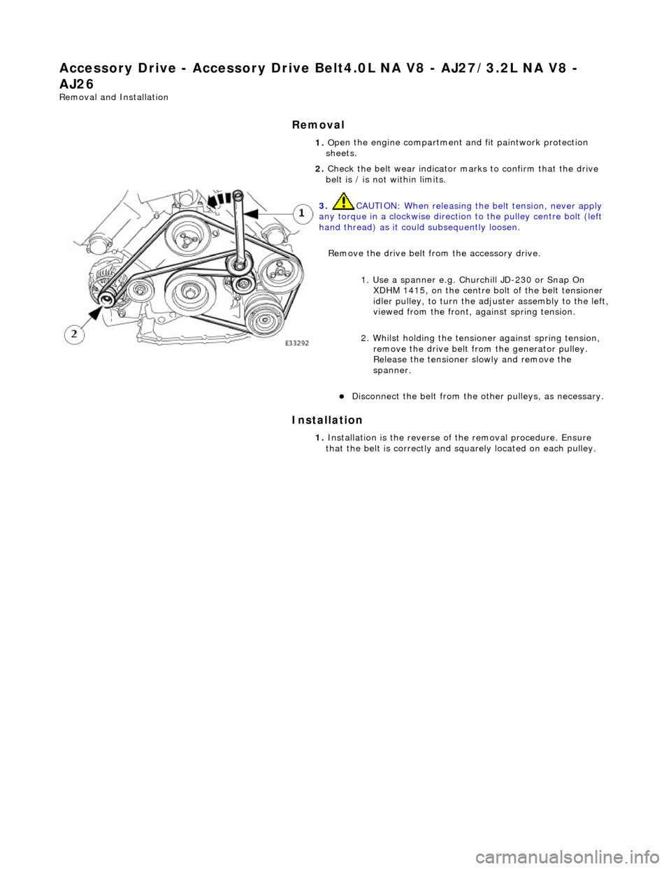
Accessory Drive - Acce
ssory
Drive Belt4.0L NA V8 - AJ27/3.2L NA V8 -
AJ26
Re
moval and Installation
Remov
al
Installation
1.
O
pen the engine compartment and fit paintwork protection
sheets.
2. Check the belt wear indicator ma rks to confirm that the drive
belt is / is not within limits.
3. CAUTI
ON: When releasing the
belt tension, never apply
any torque in a clockwise direction to the pulley ce ntre bolt (left
hand thread) as it could subsequently loosen.
Remove the drive belt fro m the accessory drive.
1. Use a spanner e.g. Churchill JD-230 or Snap On XDHM 1415, on the centre bo lt of the belt tensioner
idler pulley, to turn the adju ster assembly to the left,
viewed from the front, against spring tension.
2. Whilst holding the tensioner against spring tension, remove the drive belt from the generator pulley.
Release the tensioner sl owly and remove the
spanner.
D
isconnect the belt from the ot
her pulleys, as necessary.
1. In
stallation is the
reverse of the remova l procedure. Ensure
that the belt is correctly and sq uarely located on each pulley.