Page 358 of 1807

BR0HO-02
R07206
SST
SST
- BRAKEPROPORTIONING AND BY-PASS VALVE (P & B
VALVE)BR-65
1865 Author�: Date�:
1997 SUPRA (RM502U)
PROPORTIONING AND BY-PASS VALVE (P & B VALVE)
ON-VEHICLE INSPECTION
1. INSTALL LSPV GAUGE (SST) AND BLEED AIR
SST 09709-29017
2. RAISE MASTER CYLINDER PRESSURE AND CHECK REAR BRAKE CALIPER PRESSURE
3. INSTALL LSPV GAUGE (SST) AND BLEED AIR
SST 09709-29017
4. RAISE MASTER CYLINDER PRESSURE AND CHECK REAR BRAKE CALIPER PRESSURE
2JZ-GE Engine:
Master cylinder pressureRear brake caliper pressure
2,942 kPa (30 kgf/cm2, 427 psi)2,942 kPa (30 kgf/cm2, 427 psi)
7,845 kPa (80 kgf/cm2, 1,138 psi)4,756 kPa (48.5 kgf/cm2, 690 psi)
2JZ-GTE Engine:
Master cylinder pressureRear brake caliper pressure
2,452 kPa (25 kgf/cm2, 356 psi)2,452 kPa (25 kgf/cm2, 356 psi)
7,845 kPa (80 kgf/cm2, 1,138 psi)4,452 kPa (45.4 kgf/cm2, 646 psi)
If the rear brake caliper pressure is incorrect, replace the master cylinder.
5. BLEED BRAKE SYSTEM (See page BR-5)
6. CHECK FOR FLUID LEAKAGE
Page 360 of 1807

W03289
W03290
W03291
W03292
- BRAKEABS ACTUATOR (2JZ-GTE)
BR-73
1873 Author�: Date�:
1997 SUPRA (RM502U)
(c) Place the ºSHEET Nº (SST) on the actuator checker.
SST 09990-00410
4. INSPECT BRAKE ACTUATOR OPERATION OF
FRONT LH WHEEL
(a) Start the engine, and run it at idle.
(b) Turn the selector switch of the actuator checker to
ºFRONT RHº position.
(c) Push and hold in the MOTOR switch for a few seconds.
Make sure that you can hear the motor running.
(d) Depress the brake pedal and hold it for about 15 seconds,
and check that the pedal does not go down.
(e) With your foot still applying onto the brake pedal, push
MOTOR switch and check that the brake pedal does not
pulsate.
(f) Depress the brake pedal and hold it. As you hold the ped-
al down, push and hold in the MAIN push switch for a few
seconds. Check that the pedal does not go down.
NOTICE:
Do not keep pushing the MAIN push switch more than 10
seconds.
(g) With your foot still applying onto the brake pedal, release
the MAIN push switch and check that the pedal goes
down.
(h) With your foot still applying onto the brake pedal, push the
MOTOR switch and check that the brake pedal returns.
(i) Release the brake pedal.
5. INSPECT FOR OTHER WHEEL
(a) Turn the selector switch to the ºREAR LHº position, and
inspect the ºREAR LHº wheel.
(b) Repeating (c) to (i) in the step 4, check the actuator opera-
tion similarly.
Page 361 of 1807
BR-74
- BRAKEABS ACTUATOR (2JZ-GTE)
1874 Author�: Date�:
1997 SUPRA (RM502U)
(c) Similarly, inspect the ºREAR RHº and ºFRONT RHº wheel.
HINT:
When inspecting the ºFRONT RHº wheel, push the FRONT LH
switch instead of the MAIN push switch. This makes it possible
to inspect wherever the selector switch position indicates.
6. PUSH MOTOR SWITCH
(a) Push and hold in the MOTOR switch for a few seconds.
(b) Stop the engine.
7. DISCONNECT ACTUATOR CHECKER (SST) FROM
ACTUATOR
(a) Disconnect the actuator checker (SST) and sub-wire har-
nesses (SST) from the actuator.
SST 09990-00150, 09990-00250, 09990-00300,
09990-00360, 09990-00410
(b) Connect the 2 actuator connectors.
(c) Clear the DTC (See page DI-442).
Page 381 of 1807

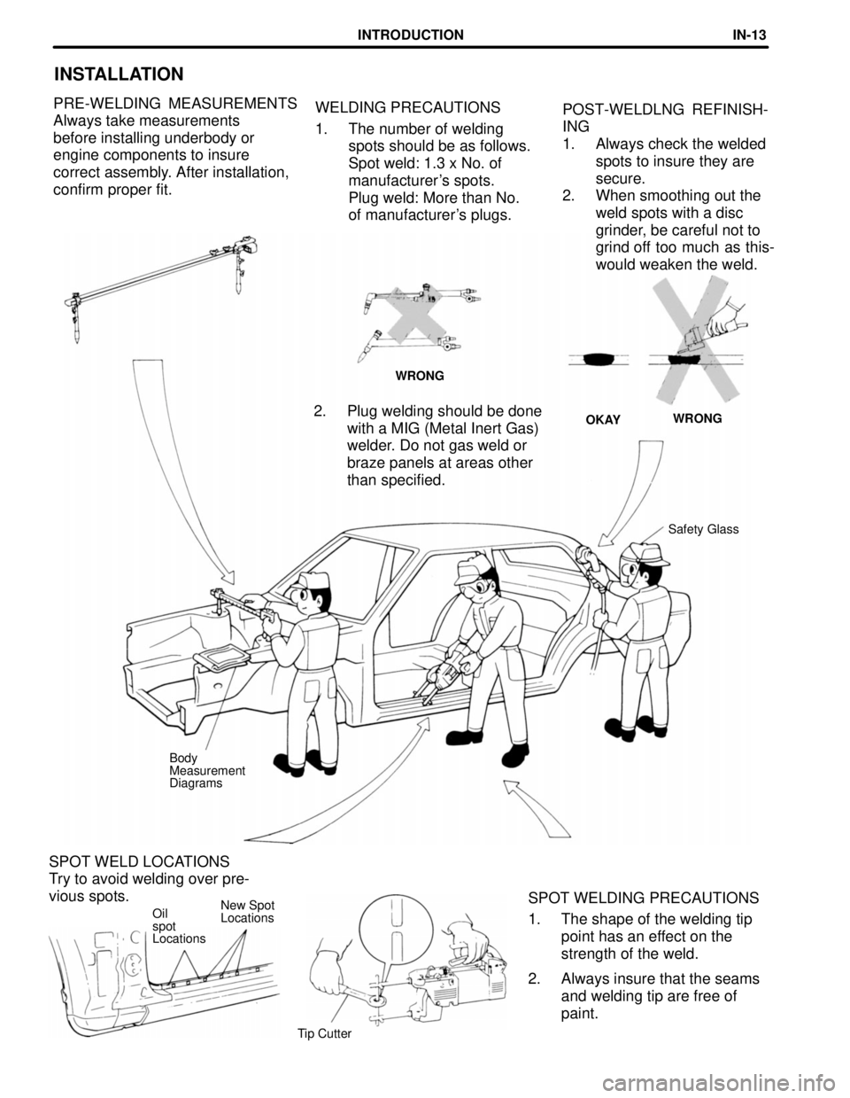
SPOT WELD LOCATIONS
Try to avoid welding over pre-
vious spots.
New Spot
Locations
WELDING PRECAUTIONS
1. The number of welding
spots should be as follows.
Spot weld: 1.3 x No. of
manufacturer's spots.
Plug weld: More than No.
of manufacturer's plugs.
INSTALLATION
POST-WELDLNG REFINISH-
ING
1. Always check the welded
spots to insure they are
secure.
2. When smoothing out the
weld spots with a disc
grinder, be careful not to
grind off too much as this-
would weaken the weld. PRE-WELDING MEASUREMENTS
Always take measurements
before installing underbody or
engine components to insure
correct assembly. After installation,
confirm proper fit.
WRONG
WRONG
OKAY
2. Plug welding should be done
with a MIG (Metal Inert Gas)
welder. Do not gas weld or
braze panels at areas other
than specified.
Safety Glass
Body
Measurement
Diagrams
SPOT WELDING PRECAUTIONS
1. The shape of the welding tip
point has an effect on the
strength of the weld.
2. Always insure that the seams
and welding tip are free of
paint.
Oil
spot
Locations
Tip Cutter
INTRODUCTIONIN-13
Page 528 of 1807
CO08J-01
- COOLINGCOOLANT
CO-1
1414 Author�: Date�:
1997 SUPRA (RM502U)
COOLANT
INSPECTION
1. CHECK ENGINE COOLANT LEVEL AT RADIATOR RESERVOIR
The engine coolant level should be between the ºLOWº and ºFULLº lines, when the engine is cold.
If low, check for leaks and add engine coolant up to the ºFULLº line.
2. CHECK ENGINE COOLANT QUALITY
(a) Remove the radiator cap.
CAUTION:
To avoid the danger of being burned, do not remove the radiator cap while the engine and radiator
are still hot, as fluid and steam can be blown out under pressure.
(b) There should not be any excessive deposits of rust or scale around the radiator cap or radiator filler
hole, and the coolant should be free from oil.
If excessively dirty, replace the coolant.
(c) Reinstall the radiator cap.
Page 529 of 1807

CO0ZY-01
Z07402
Drain Plug
Drain Plug CO-2
- COOLINGCOOLANT
1415 Author�: Date�:
1997 SUPRA (RM502U)
REPLACEMENT
1. DRAIN ENGINE COOLANT
(a) Remove the radiator cap.
CAUTION:
To avoid the danger of being burned, do not remove the ra-
diator cap while the engine and radiator are still hot, as fluid
and steam can be blown out under pressure.
(b) Loosen the 2 drain plugs (for the engine and radiator),
and drain the coolant.
HINT:
To prevent the coolant from spraying over the cylinder block,
connect the rubber hose (inside diameter 6 - 8 mm) in the mar-
ket to the union pipe under.
(c) Close the drain plugs.
Torque:
Engine drain plug
29 N´m (300 kgf´cm, 22 ft´lbf)
2. FILL ENGINE COOLANT
(a) Slowly fill the system with coolant.
�Use a good brand of ethylene-glycol base coolant
and mix it according to the manufacturer's direc-
tions.
�Using coolant which includes more than 50 % ethyl-
ene-glycol (but not more than 70 %) is recom-
mended.
NOTICE:
�Do not use an alcohol type coolant.
�The coolant should be mixed with demineralized wa-
ter or distilled water.
Capacity (w/ Heater):
M/TA/T
2JZ-GE7.3 liters
(7.7 US qts, 6.4 lmp. qts)8.3 liters
(8.8 US qts, 7.3 lmp. qts)
2JZ-GTE8.9 liters
(9.4 US qts, 7.8 lmp. qts)8.8 liters
(9.3 US qts, 7.7 lmp. qts)
(b) Install the radiator cap.
(c) Start the engine, and bleed the cooling system.
(d) Refill the reservoir with coolant until it reaches the
ºFULLº line.
3. CHECK ENGINE COOLANT FOR LEAKS
Page 543 of 1807
CO08S-01
P11770
Jiggle Valve
Protrusion 2JZ-GE
2JZ-GTE CO-16
- COOLINGTHERMOSTAT
1429 Author�: Date�:
1997 SUPRA (RM502U)
INSTALLATION
1. PLACE THERMOSTAT IN WATER INLET
(a) Install a new gasket to the thermostat.
(b) Align the jiggle valve of the thermostat with the protrusion
of the water inlet.
2. INSTALL WATER INLET
(a) Install the water inlet with the 2 nuts.
Torque:
2JZ-GE 8.8 N´m (90 kgf´cm, 78 in.´lbf)
2JZ-GTE 21 N´m (210 kgf´cm, 15 ft´lbf)
(b) 2JZ-GTE:
Connect the lower radiator hose to the radiator.
3. 2JZ-GTE:
INSTALL ENGINE UNDER COVER
4. FILL WITH ENGINE COOLANT
5. START ENGINE AND CHECK FOR COOLANT
LEAKS
Page 545 of 1807

Z00570
Radiator Cap Tester
30° or More
Radiator Cap
P11504
CO08U-01
CO-18
- COOLINGRADIATOR
1431 Author�: Date�:
1997 SUPRA (RM502U)
ON-VEHICLE INSPECTION
1. REMOVE RADIATOR CAP
CAUTION:
To avoid the danger of being burned, do not remove the ra-
diator cap while the engine and radiator are still hot, as fluid
and steam can be blown out under pressure.
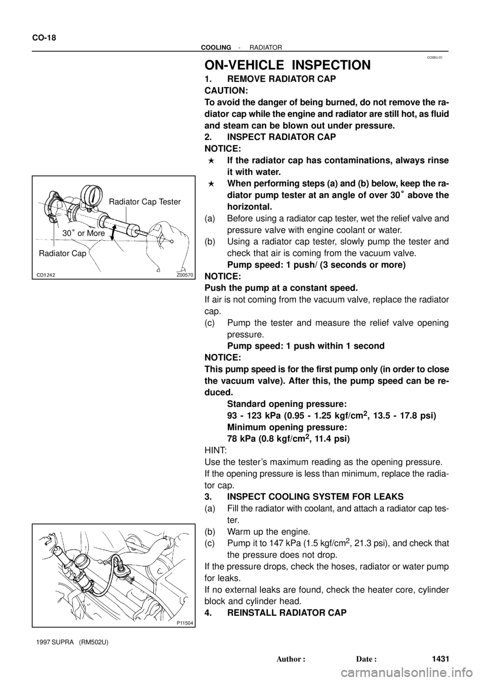
2. INSPECT RADIATOR CAP
NOTICE:
�If the radiator cap has contaminations, always rinse
it with water.
�When performing steps (a) and (b) below, keep the ra-
diator pump tester at an angle of over 30° above the
horizontal.
(a) Before using a radiator cap tester, wet the relief valve and
pressure valve with engine coolant or water.
(b) Using a radiator cap tester, slowly pump the tester and
check that air is coming from the vacuum valve.
Pump speed: 1 push/ (3 seconds or more)
NOTICE:
Push the pump at a constant speed.
If air is not coming from the vacuum valve, replace the radiator
cap.
(c) Pump the tester and measure the relief valve opening
pressure.
Pump speed: 1 push within 1 second
NOTICE:
This pump speed is for the first pump only (in order to close
the vacuum valve). After this, the pump speed can be re-
duced.
Standard opening pressure:
93 - 123 kPa (0.95 - 1.25 kgf/cm
2, 13.5 - 17.8 psi)
Minimum opening pressure:
78 kPa (0.8 kgf/cm
2, 11.4 psi)
HINT:
Use the tester's maximum reading as the opening pressure.
If the opening pressure is less than minimum, replace the radia-
tor cap.
3. INSPECT COOLING SYSTEM FOR LEAKS
(a) Fill the radiator with coolant, and attach a radiator cap tes-
ter.
(b) Warm up the engine.
(c) Pump it to 147 kPa (1.5 kgf/cm
2, 21.3 psi), and check that
the pressure does not drop.
If the pressure drops, check the hoses, radiator or water pump
for leaks.
If no external leaks are found, check the heater core, cylinder
block and cylinder head.
4. REINSTALL RADIATOR CAP