Page 573 of 1807

386 Author�: Date�:
1997 SUPRA (RM502U)
DIAGNOSTIC TROUBLE CODE CHART
HINT:
Parameters listed in the chart may not be exactly the same as your reading d")
DI4SI-01
DI-158
- DIAGNOSTICSENGINE (2JZ-GTE)
386 Author�: Date�:
1997 SUPRA (RM502U)
DIAGNOSTIC TROUBLE CODE CHART
HINT:
Parameters listed in the chart may not be exactly the same as your reading due to the type of instrument
or other factors.
If a malfunction code is displayed during the DTC check in check mode, check the circuit for that code listed
in the table below. For details of each code, turn to the page reffered to under the ºSee pageº for the respec-
tive ºDTC No.º in the DTC chart.
DTC No.
(See Page)Detection ItemTrouble AreaMIL*Memory
P0100
(DI-170)Mass Air Flow Circuit
Malfunction�Open or short in mass air flow meter circuit
�Mass air flow meter
�ECM
��
P0101
(DI-174)Mass Air Flow Circuit
Range / Performance Problem�Mass air flow meter��
P0110
(DI-175)Intake Air Temp. Circuit
Malfunction�Open or short in intake air temp. sensor circuit
�Intake air temp. sensor
�ECM
��
P0115
(DI-179)Engine Coolant Temp. Circuit
Malfunction�Open or short in engine coolant temp. sensor circuit
�Engine coolant temp. sensor
�ECM
��
P0116
(DI-183)Engine Coolant Temp. Circuit
Range / Performance Problem�Engine coolant temp. sensor
�Cooling system��
P0120
(DI-184)Throttle / Pedal Position
Sensor / Switch ºAº Circuit
Malfunction�Open or short in throttle position sensor circuit
�Throttle position sensor
�ECM
��
P0121
(DI-189)Throttle /Pedal Position
Sensor / Switch ºAº Circuit
Range / Peformance Problem
�Throttle position sensor��
P0125
(DI-190)Insufficient Coolant Temp. for
Closed Loop Fuel Control�Open or short in heated oxygen sensor circuit
�Heated oxygen sensor��
P130
(DI-193)Heated Oxygen Sendor Circuit
Malfunction
(Bank 1 Sensor 1)�Heated oxygen sensor
�Fuel trim malfunction��
P0133
(DI-196)Heated Oxygen Sensor Circuit
Slow Response
(Bank 1 Sensor 1)
�Heated oxygen sensor��
*: �... MIL lights up
Page 579 of 1807
 DI-164
- DIAGNO")
DI4SK-01
S00576
P11278
ECM
FI6451
CHECK HARNESS A
ECU
FI6522
Before Connection
After Connection
Female
Connector Bolt
Collar
Stopper
Nut
Connector
Male
FI6523
Less Than 1 mm (0.04 in.) DI-164
- DIAGNOSTICSENGINE (2JZ-GTE)
392 Author�: Date�:
1997 SUPRA (RM502U)
TERMINALS OF ECM
Connectors of the ECM are water-proof and are the bolt type.
For water proof type connectors, in order to measure the volt-
age of ECM terminals and the resistance of connected parts,
connect the inspection check harness between the ECM and
vehicle wire harness, then perform the inspection.
The inspection method of inserting a tester probe from the other
side of connector noticeably reduces the water-proof ability.
Disconnect the connector by fully loosening the bolt.
PREPARATION
(a) Turn the ignition switch to LOCK position.
(b) Turn up the passenger side floor mat.
(c) Remove the ECM protector.
(d) Disconnect the connectors from the ECM.
After completely loosening the bolt, the 2 parts of connec-
tor can be separated.
NOTICE:
�Do not pully the wire harness when disconnecting the
connector.
�When disconnecting the connector, the ECM's back-
up power source is cut off, so the DTC, etc. recorded
in the ECM memory are cancelled.
�Never insert a tester probe or male terminal used for
inspection purposes into the female terminal of the
vehicle wire harness. Otherwise, the female terminal
may be widened, which can result in faulty connec-
tion.
(e) Connect the Check Harness A between ECM and con-
nector of vehicle wire harness.
SST 09990-01000
HINT:
The arrangement of the DLC1 terminals are the same as those
of the ECM (See page DI-164).
(f) Disconnect the Check Harness A.
(g) Reconnect the connectors to the ECM.
(1) Match the male connector correctly with female
connector, then press them together.
(2) Tighten the bolt.
Make sure the connector is completely connected,
by tightening the bolt until there is a clearance of
less than 1 mm (0.04 in.) between bottom of the
male connector and end of the female connector.
(h) Install the ECM protector and floor mat.
Page 584 of 1807

DI-169
397 Author�: Date�:
1997 SUPRA (RM502U)
PROBLEM SYMPTOMS TABLE
When the malfunction code is not confirmed in the DTC check and the problem still can not")
DI4SL-01
- DIAGNOSTICSENGINE (2JZ-GTE)
DI-169
397 Author�: Date�:
1997 SUPRA (RM502U)
PROBLEM SYMPTOMS TABLE
When the malfunction code is not confirmed in the DTC check and the problem still can not be confirmed
in the basic inspection, then proceed to this step and perform troubleshooting according to the numbered
order given in the table below.
SymptomSuspect AreaSee page
Does not start (Engine does not crank)1. Starter and Starter relayST-14, ST-16
Does not start (No initial combustion)
1. ECM power source circuit
2. Fuel pump control circuit
3. Engine control module (ECM)DI-304
DI-248
IN-18
Does not start (No complete combustion)1. Fuel pump control circuitDI-248
Difficult to start (Engine cranks normally)
1. Starter signal circuit
2. Fuel pump control circuit
3. CompressionDI-301
DI-248
EM-3
Difficult to start (Cold engine)1. Starter signal circuit
2.Fuel pump control circuitDI-301
DI-248
Difficult to start (Hot engine)
1. Starter signal circuit
2. Fuel pressure control circuit
3. Fuel pump control circuitDI-301
DI-309
DI-248
Poor idling (High engine idle speed)1. A/C signal circuit
2. ECM power source circuitDI-722
DI-304
Poor idling (Low engine idle speed)1. A/C signal circuit
2. Fuel pump control circuitDI-722
DI-248
Poor idling (Rough idling)1. Compression
2. Fuel pump control circuitEM-3
DI-248
Poor idling (Hunting)1. ECM power source circuit
2. Fuel pump control circuitDI-304
DI-248
Poor Driveability (Hesitation/Poor acceleration)1. Fuel pump control circuit
2. A/T faultyDI-248
DI-391
Poor Driveability (Surging)1. Fuel pump control circuitDI-248
Engine stall (Soon after starting)1. Fuel pump control circuitDI-248
Engine stall (During A/C operation)1. A/C signal circuit
2. Engine control module (ECM)DI-722
IN-18
Page 586 of 1807
FI6930
B-W
R/B No.22
2A
EFI No.1 B
BatteryEFI Main RelayB-R R/B No.2
B-Y
W-B
EBEA2
2
22
2 23
5
1
EA1
8
5
1
Mass Air Flow Meter2
5Y-R
B-RA
B
B 66
28
E2G
E1 VG GR24
M-RELB+ ECM
1
- DIAGNOSTICSENGINE (2JZ-GTE)
DI-171
399 Author�: Date�:
1997 SUPRA (RM502U)
WIRING DIAGRAM
INSPECTION PROCEDURE
1 Connect the OBD II scan tool or TOYOTA hand-held tester, and read value of
mass air flow rate.
RESULT:
(a) Connect the OBD II scan tool or TOYOTA hand-held tester to the DLC3.
(b) Turn ignition switch ON and push the OBD II scan tool or TOYOTA hand-held tester main switch ON.
(c) Start the engine.
CHECK:
Read mass air flow rate on the OBD II scan tool or TOYOTA hand-held tester.
RESULT:
Type IType II
Mass air flow rate0.0 gm / sec.359.0 gm / sec. or more
Type I Go to step 2.
Type II Go to step 5.
Page 587 of 1807
BE6653
P24310A00099
ON
1(+)
A00689
STARTCheck Harness A
ECM
B66 VG(+)
DI-172
- DIAGNOSTICSENGINE (2JZ-GTE)
400 Author�: Date�:
1997 SUPRA (RM502U)
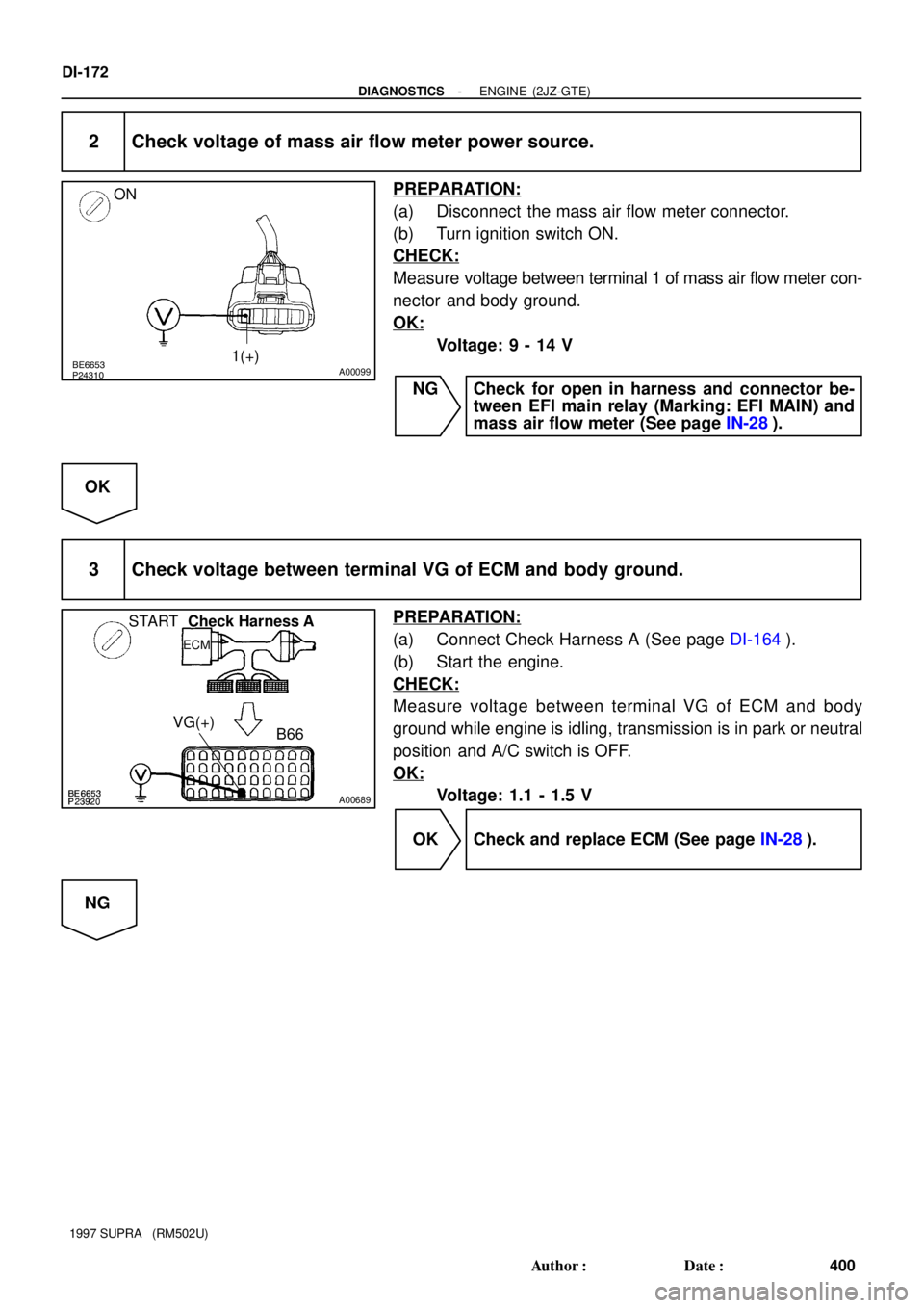
2 Check voltage of mass air flow meter power source.
PREPARATION:
(a) Disconnect the mass air flow meter connector.
(b) Turn ignition switch ON.
CHECK:
Measure voltage between terminal 1 of mass air flow meter con-
nector and body ground.
OK:
Voltage: 9 - 14 V
NG Check for open in harness and connector be-
tween EFI main relay (Marking: EFI MAIN) and
mass air flow meter (See page IN-28).
OK
3 Check voltage between terminal VG of ECM and body ground.
PREPARATION:
(a) Connect Check Harness A (See page DI-164).
(b) Start the engine.
CHECK:
Measure voltage between terminal VG of ECM and body
ground while engine is idling, transmission is in park or neutral
position and A/C switch is OFF.
OK:
Voltage: 1.1 - 1.5 V
OK Check and replace ECM (See page IN-28).
NG
Page 588 of 1807
S00344
Check Harness A
ECM
B28 E2G
- DIAGNOSTICSENGINE (2JZ-GTE)
DI-173
401 Author�: Date�:
1997 SUPRA (RM502U)
4 Check for open and short in harness and connector between mass air flow meter
and ECM (See page IN-28).
NG Repair or replace harness or connector.
OK
Replace mass air flow meter.
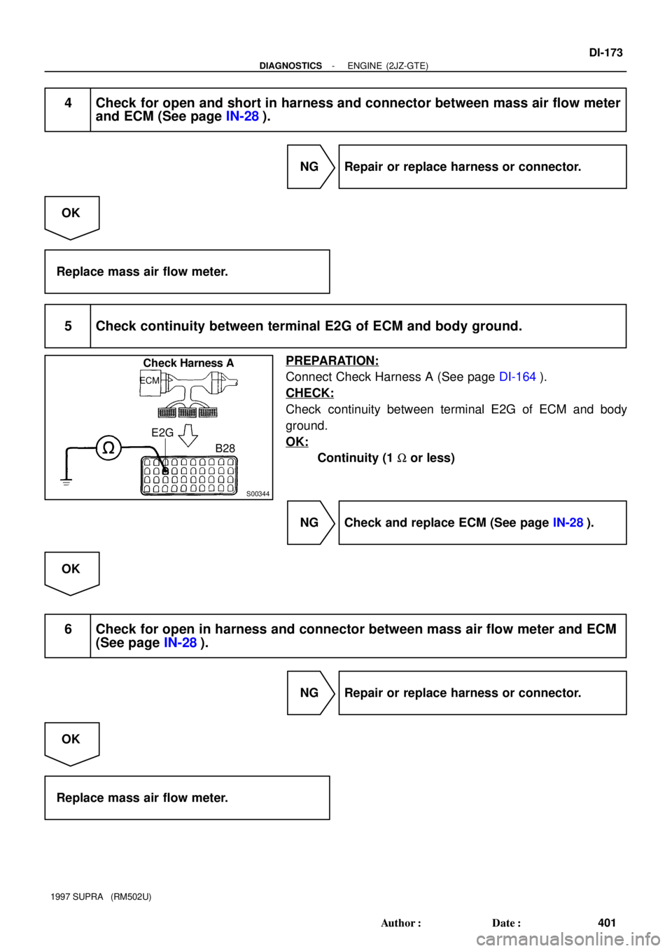
5 Check continuity between terminal E2G of ECM and body ground.
PREPARATION:
Connect Check Harness A (See page DI-164).
CHECK:
Check continuity between terminal E2G of ECM and body
ground.
OK:
Continuity (1 W or less)
NG Check and replace ECM (See page IN-28).
OK
6 Check for open in harness and connector between mass air flow meter and ECM
(See page IN-28).
NG Repair or replace harness or connector.
OK
Replace mass air flow meter.
Page 591 of 1807

3
4P-L
W-B45
65B
BECM
5V
THAR
E2
E2
DI-176
- DIAGNOSTICSENGINE (2JZ-GTE)
404 Author�: Date�:
1997 SUPRA (RM502U)
WIRING DIAGRAM
INSPEC")
FI6448
Intake Air Temp. Sensor
(Inside the mass air flow meter)
3
4P-L
W-B45
65B
BECM
5V
THAR
E2
E2
DI-176
- DIAGNOSTICSENGINE (2JZ-GTE)
404 Author�: Date�:
1997 SUPRA (RM502U)
WIRING DIAGRAM
INSPECTION PROCEDURE
HINT:
�If DTC ºP0110º (Intake Air Temp. Circuit Malfunction), ºP0115º (Engine Coolant Temp. Circuit Malfunc-
tion), ºP0120º (Throttle/Pedal Position Sensor/Switch ºAº Circuit Malfunction), are output simulta-
neously, E2 (sensor ground) may be open.
1 Connect the OBD II scan tool or TOYOTA hand-held tester, and read value of in-
take air temperature.
PREPARATION:
(a) Connect the OBD II scan tool or TOYOTA hand-held tester to the DLC3.
(b) Turn ignition switch ON and push the OBD II scan tool or TOYOTA hand-held tester main switch ON.
CHECK:
Read temperature value on the OBD II scan tool or TOYOTA hand-held tester.
OK:
Same as actual intake air temperature.
HINT:
�If there is open circuit, OBD II scan tool or TOYOTA hand-held tester indicates - 40°C (- 40°F).
�If there is short circuit, OBD II scan tool or TOYOTA hand-held tester indicates 140°C (284°F) or more.
NG - 40 °C (- 40 °F) ............. Go to step 2.
140 °C (284 °F) or more .. Go to step 4.
OK
Check for intermittent problems.
(See page DI-147)
Page 592 of 1807

D")
BE6653
A00347
A00348
ON
Intake Air
Temp. Sensor
3
4ECM
5V
THA
E2 B
B 45
65
A00690
ON
Intake Air
Temp. Sensor3
445
65
B
B
ECM
5V
THA
E2
Check Harnss A
B45, 65
THA
E2
ECM
- DIAGNOSTICSENGINE (2JZ-GTE)
DI-177
405 Author�: Date�:
1997 SUPRA (RM502U)
2 Check for open in harness or ECM.
PREPARATION:
(a) Disconnect the mass air flow meter connector.
(b) Connect sensor wire harness terminals together.
(c) Turn ignition switch ON.
CHECK:
Read temperature value on the OBD II scan tool or TOYOTA
hand-held tester.
OK:
Temperature value: 140°C (284°F) or more
OK Confirm good connection at sensor.
If OK, replace mass air flow meter.
NG
3 Check for open in harness or ECM.
PREPARATION:
(a) Connect Check Harness A (See page DI-164).
(b) Connect between terminals THA and E2 of ECM connec-
tor.
HINT:
Mass air flow meter connector is disconnected. Before check-
ing, do a visual and contact pressure check for the ECM con-
nector (See page IN-28).
(c) Turn ignition switch ON.
CHECK:
Read temperature value on the OBD II scan tool or TOYOTA
hand-held tester.
OK:
Temperature value: 140°C (284°F) or more
OK Open in harness between terminals E2 or THA,
repair or replace harness.
NG
Confirm good connection at ECM.
If OK, replace ECM.