Page 675 of 1807
S03246S02441A03142
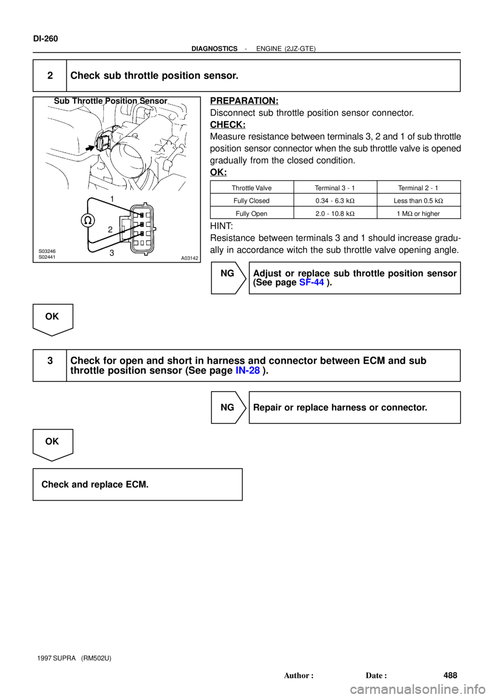
Sub Throttle Position Sensor
1
2
3
DI-260
- DIAGNOSTICSENGINE (2JZ-GTE)
488 Author�: Date�:
1997 SUPRA (RM502U)
2 Check sub throttle position sensor.
PREPARATION:
Disconnect sub throttle position sensor connector.
CHECK:
Measure resistance between terminals 3, 2 and 1 of sub throttle
position sensor connector when the sub throttle valve is opened
gradually from the closed condition.
OK:
Throttle ValveTerminal 3 - 1Terminal 2 - 1
Fully Closed0.34 - 6.3 kWLess than 0.5 kW
Fully Open2.0 - 10.8 kW1 MW or higher
HINT:
Resistance between terminals 3 and 1 should increase gradu-
ally in accordance witch the sub throttle valve opening angle.
NG Adjust or replace sub throttle position sensor
(See page SF-44).
OK
3 Check for open and short in harness and connector between ECM and sub
throttle position sensor (See page IN-28).
NG Repair or replace harness or connector.
OK
Check and replace ECM.
Page 676 of 1807
- DIAGNOSTICSENGINE (2JZ-GTE)
DI-261
489 Author�: Date�:
1997 SUPRA (RM502U)
DTC P1401 Sub Throttle Position Sensor Range/
Performance Problem
CIRCUIT DESCRIPTION
Refer to ºSub Throttle Position Sensor Malfunctionº on page DI-258.
DTC No.DTC Detecting ConditionTrouble Area
P1401
Condition (a) and (b) continue for 10 sec. or more
(2 trip detection logic)
(a) During driving the road that difficult to slip with ºAUTO
modeº
(b) The difference of the throttle valve open angle and the
sub throttle valve opening angle is greater than 35°
�Sub throttle position sensor
INSPECTION PROCEDURE
1 Are there any other codes (besides DTC P1401) being output?
YES Go to relevant DTC chart.
NO
Replace sub throttle position sensor.
DI4TF-01
Page 677 of 1807

490 Author�: Date�:
1997 SUPRA (RM502U)
DTC P1405 Turbo Pressure Sensor Circuit")
S03258
Turbo Pressure Sensor
3
2
1L-R
B-Y
W-B41
62
65B
B
BECM
5V
VCC
5V
PM1
E2
E1 DI-262
- DIAGNOSTICSENGINE (2JZ-GTE)
490 Author�: Date�:
1997 SUPRA (RM502U)
DTC P1405 Turbo Pressure Sensor Circuit Malfunction
CIRCUIT DESCRIPTION
The sensor detects the air intake chamber pressure and converts the pressure reading into a voltage which
is used to control the turbo pressure by the ECM.
If the ECM detects the below diagnosis conditions, it operates the fail safe function to open the waste gate
valve fully.
DTC No.DTC Detecting ConditionTrouble Area
P1405Open or short in turbo pressure sensor circuit
�Open or short in turbo pressure sensor circuit
�Turbo pressure sensor
�ECM
If the ECM detects DTC ºP1405º it operates the fail safe function, keeping the ignition timing and infection
volume constant and making it possible to drive the vehicle.
HINT:
After confirming DTC P1405 use the OBD II scan tool or TOYOTA hand-held tester to confirm the turbo ab-
solute pressure from ºCURRENT DATAº.
Turbo Absolute PressureMalfunction
0 kPaPIM circuit short
130 kPa or more
VC circuit open or short
PIM circuit open
E2 circuit open
WIRING DIAGRAM
DI4TG-01
Page 678 of 1807
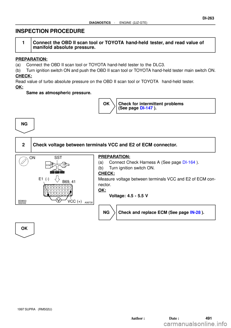
BE6653S02442A06730
SST
E1 (-)
B69, 41
VCC (+)
ECM
ON
- DIAGNOSTICSENGINE (2JZ-GTE)
DI-263
491 Author�: Date�:
1997 SUPRA (RM502U)
INSPECTION PROCEDURE
1 Connect the OBD II scan tool or TOYOTA hand-held tester, and read value of
manifold absolute pressure.
PREPARATION:
(a) Connect the OBD II scan tool or TOYOTA hand-held tester to the DLC3.
(b) Turn ignition switch ON and push the OBD II scan tool or TOYOTA hand-held tester main switch ON.
CHECK:
Read value of turbo absolute pressure on the OBD II scan tool or TOYOTA hand-held tester.
OK:
Same as atmospheric pressure.
OK Check for intermittent problems
(See page DI-147).
NG
2 Check voltage between terminals VCC and E2 of ECM connector.
PREPARATION:
(a) Connect Check Harness A (See page DI-164).
(b) Turn ignition switch ON.
CHECK:
Measure voltage between terminals VCC and E2 of ECM con-
nector.
OK:
Voltage: 4.5 - 5.5 V
NG Check and replace ECM (See page IN-28).
OK
Page 679 of 1807
BE6653S02443A03143
ON
SST
ECM
B65, 62
PM1(+)
E2(-)
DI-264
- DIAGNOSTICSENGINE (2JZ-GTE)
492 Author�: Date�:
1997 SUPRA (RM502U)
3 Check voltage between terminals PM1 and E2 of ECM connector.
PREPARATION:
(a) Connect Check Harness A (See page DI-164).
(b) Turn ignition switch ON.
CHECK:
Measure voltage between terminals PM1 and E2 of ECM con-
nector.
OK:
Voltage: 2.3 - 3.0 V
OK Check and replace ECM (See page IN-28).
NG
4 Check for open and short in harness and connector between turbo pressure
sensor and ECM.
NG Repair or replace harness or connector.
OK
Replace turbo pressure sensor.
Page 680 of 1807
- DIAGNOSTICSENGINE (2JZ-GTE)
DI-265
493 Author�: Date�:
1997 SUPRA (RM502U)
DTC P1406 Turbo Pressure Sensor Circuit Range/
Performance Problem
CIRCUIT DESCRIPTION
Refer to ºTurbo Pressure Sensor Malfunctionº on page DI-262.
DTC No.DTC Detecting ConditionTrouble Area
P1406
Conditions (a) and (b) continue for 5 sec. or more
(2 trip detection logic)
(a) Turbo pressure sensor output < 1.2 V
(b) Mass air flow > 1.3 g/rev
TbP1406Conditions (a) and (b) continue for 5 sec. or more
(2 trip detection logic)
(a) Turbo pressure sensor output > 4.2 V
(b) Mass air flow < 0.45 g/rev�Turbo pressure sensor
WIRING DIAGRAM
Refer to page DI-262 for the WIRING DIAGRAM.
INSPECTION PROCEDURE
1 Are there any other codes (besides DTC P1406) being output?
YES Go to relevant DTC chart.
NO
Replace turbo pressure sensor.
DI4TH-01
Page 681 of 1807

VSV for Exhaust
Bypass Valve
Actuator
(for Exhaust
Bypass Valve)
VSV for Intake Air Control Valve
Actuator (for Intake")
S03236
VSV for Exhaust Gas Control Valve
Actuator (for Exhaust Gas Control Valve)
VSV for Exhaust
Bypass Valve
Actuator
(for Exhaust
Bypass Valve)
VSV for Intake Air Control Valve
Actuator (for Intake Air Control Valve) Exhaust Manifold
Intake Manifold CAC Air Bypass Valve Actuator
(for Waste Gate Valve)Air
Cleaner VSV for Waste
Gate Valve
Waste Gate
Valve
ECM
DI-266
- DIAGNOSTICSENGINE (2JZ-GTE)
494 Author�: Date�:
1997 SUPRA (RM502U)
DTC P1511 Boost Pressure Low Malfunction
CIRCUIT DESCRIPTION
To control maximum turbocharging pressure the turbocharger system includes a waste gate valve or exhaust
bypass valve controlled by an actuator. The actuator is controlled by the manifold pressure which is duty
controlled by the VSV based on signals from the ECM.
DTC No.DTC Detecting ConditionTrouble Area
P1511
Under the following conditions (a), (b) and (c):
(a) After the engine is warmed up
(b) Engine rotation speed is 2,600 rpm is more
(c) At the time of WOT, under the condition with +150 mmHg or
less of intake pipe pressure
(2 trip detection logic)�Actuator (for waste gate valve, intake air control valve, ex-
haust gas control valve, and exhaust bypass valve)
�Short in VSV for waste gate valve, intake air control valve,
exhaust gas control valve and exhaust bypass valve circuit
�ECM
�Air intake (leakage or clogging)
DI4TI-01
Page 682 of 1807
BE6653S03250S03251
A03145
ON
Air Air
E
FE
F
VSV: OFF VSV: ON
- DIAGNOSTICSENGINE (2JZ-GTE)
DI-267
495 Author�: Date�:
1997 SUPRA (RM502U)
INSPECTION PROCEDURE
TOYOTA hand-held tester
1 Connect the TOYOTA hand-held tester and check operation of VSV for waste
gate valve.
PREPARATION:
(a) Connect the TOYOTA hand-held tester to the DLC3.
(b) Turn ignition switch ON and TOYOTA hand-held tester
main switch ON.
(c) Select the ACTIVE TEST mode on the TOYOTA hand-
held tester.
CHECK:
Check operation of VSV when VSV is operated by the TOYOTA
hand-held tester.
OK:
VSV is ON:
Air from pipe E flows out through pipe F.
VSV is OFF:
Air does not flow from pipe E to pipe F.
OK Go to step 3.
NG
2 Check VSV for waste gate valve (See page SF-63).
NG Replace VSV for waste gate valve.
OK