Page 1298 of 1807
P12308
SST
P02269
EM-46
- ENGINE MECHANICAL (2JZ-GTE)CYLINDER HEAD
1151 Author�: Date�:
1997 SUPRA (RM502U)
(c) Using SST, compress the valve spring and place the 2
keepers around the valve stem.
SST 09202-70020 (09202-00010)
(d) Using a plastic-faced hammer, lightly tap the valve stem
tip to ensure a proper fit.
3. INSTALL VALVE LIFTERS AND SHIMS
(a) Install the valve lifter and shim.
(b) Check that the valve lifter rotates smoothly by hand.
4. INSTALL EGR COOLER
Install a new gasket and the EGR cooler with the 8 bolts.
Torque: 8.8 N´m (90 kgf´cm, 78 in.´lbf)
5. INSTALL CAMSHAFT POSITION SENSORS
Install the gasket and sensor with the 2 bolts.
Torque: 8.8 N´m (90 kgf´cm, 78 in.´lbf)
6. INSTALL ENGINE HANGERS AND GROUND STRAP
Torque: 39 N´m (400 kgf´cm, 29 ft´lbf)
Page 1299 of 1807
EM0AM-02
P02111
Z02387
10 mm
Bi-Hexagon
Wrench
12
14 1013
11 84
6125
379
P02424
Painted Mark
Front
P02425
Painted Mark
90°
90°90°
90°
- ENGINE MECHANICAL (2JZ-GTE)CYLINDER HEAD
EM-47
1152 Author�: Date�:
1997 SUPRA (RM502U)
INSTALLATION
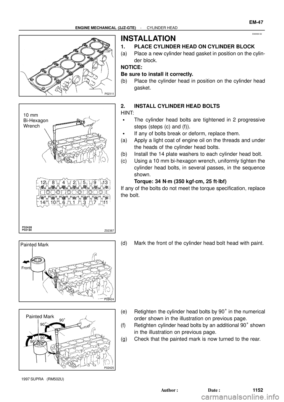
1. PLACE CYLINDER HEAD ON CYLINDER BLOCK
(a) Place a new cylinder head gasket in position on the cylin-
der block.
NOTICE:
Be sure to install it correctly.
(b) Place the cylinder head in position on the cylinder head
gasket.
2. INSTALL CYLINDER HEAD BOLTS
HINT:
�The cylinder head bolts are tightened in 2 progressive
steps (steps (c) and (f)).
�If any of bolts break or deform, replace them.
(a) Apply a light coat of engine oil on the threads and under
the heads of the cylinder head bolts.
(b) Install the 14 plate washers to each cylinder head bolt.
(c) Using a 10 mm bi-hexagon wrench, uniformly tighten the
cylinder head bolts, in several passes, in the sequence
shown.
Torque: 34 N´m (350 kgf´cm, 25 ft´lbf)
If any of the bolts do not meet the torque specification, replace
the bolt.
(d) Mark the front of the cylinder head bolt head with paint.
(e) Retighten the cylinder head bolts by 90° in the numerical
order shown in the illustration on previous page.
(f) Retighten cylinder head bolts by an additional 90° shown
in the illustration on previous page.
(g) Check that the painted mark is now turned to the rear.
Page 1302 of 1807
P02694
P02695
120°120°
P02696
120°
120°
A02174
P03960
EM-50
- ENGINE MECHANICAL (2JZ-GTE)CYLINDER HEAD
1155 Author�: Date�:
1997 SUPRA (RM502U)
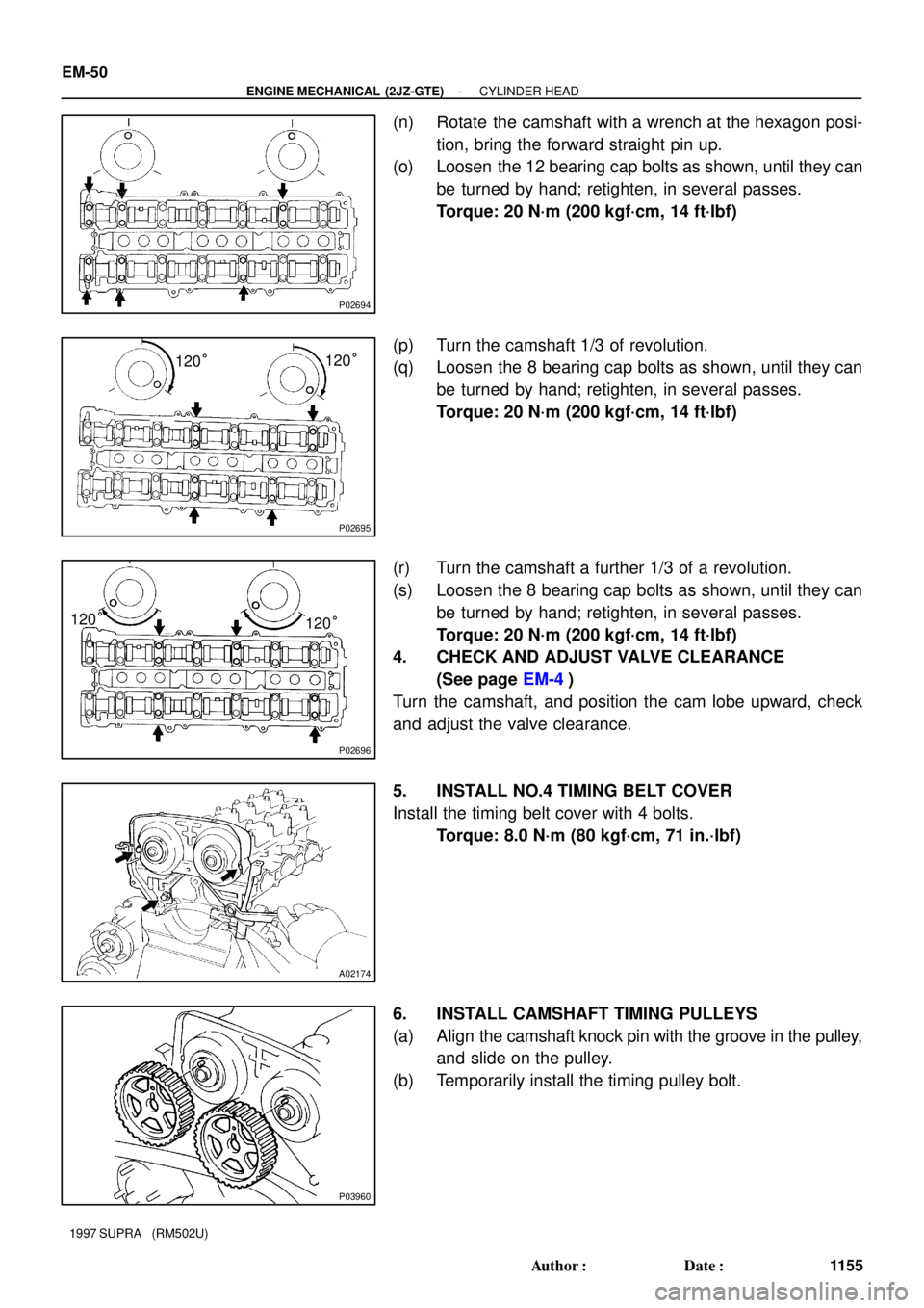
(n) Rotate the camshaft with a wrench at the hexagon posi-
tion, bring the forward straight pin up.
(o) Loosen the 12 bearing cap bolts as shown, until they can
be turned by hand; retighten, in several passes.
Torque: 20 N´m (200 kgf´cm, 14 ft´lbf)
(p) Turn the camshaft 1/3 of revolution.
(q) Loosen the 8 bearing cap bolts as shown, until they can
be turned by hand; retighten, in several passes.
Torque: 20 N´m (200 kgf´cm, 14 ft´lbf)
(r) Turn the camshaft a further 1/3 of a revolution.
(s) Loosen the 8 bearing cap bolts as shown, until they can
be turned by hand; retighten, in several passes.
Torque: 20 N´m (200 kgf´cm, 14 ft´lbf)
4. CHECK AND ADJUST VALVE CLEARANCE
(See page EM-4)
Turn the camshaft, and position the cam lobe upward, check
and adjust the valve clearance.
5. INSTALL NO.4 TIMING BELT COVER
Install the timing belt cover with 4 bolts.
Torque: 8.0 N´m (80 kgf´cm, 71 in.´lbf)
6. INSTALL CAMSHAFT TIMING PULLEYS
(a) Align the camshaft knock pin with the groove in the pulley,
and slide on the pulley.
(b) Temporarily install the timing pulley bolt.
Page 1317 of 1807
Z16735
A/T
EM0AW-03
Z09545
M/T
A/T
P13200
P13202
Z16756
M/T
Matchmarks
- ENGINE MECHANICAL (2JZ-GTE)ENGINE UNIT
EM-65
1170 Author�: Date�:
1997 SUPRA (RM502U)
INSTALLATION
1. A/T:
CHECK TORQUE CONVERTER CLUTCH
INSTALLATION
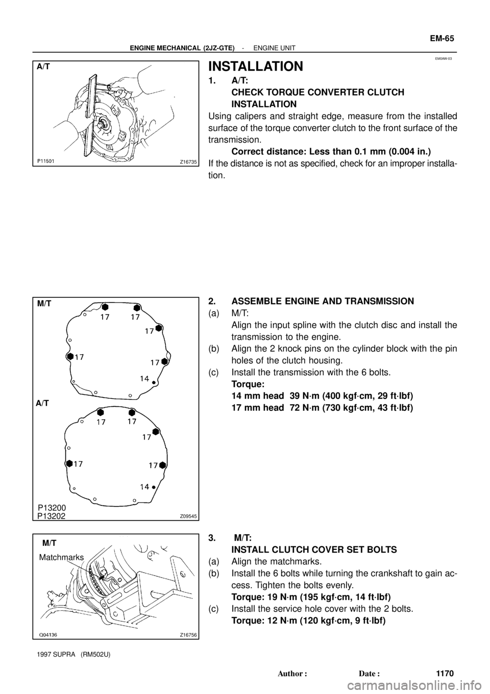
Using calipers and straight edge, measure from the installed
surface of the torque converter clutch to the front surface of the
transmission.
Correct distance: Less than 0.1 mm (0.004 in.)
If the distance is not as specified, check for an improper installa-
tion.
2. ASSEMBLE ENGINE AND TRANSMISSION
(a) M/T:
Align the input spline with the clutch disc and install the
transmission to the engine.
(b) Align the 2 knock pins on the cylinder block with the pin
holes of the clutch housing.
(c) Install the transmission with the 6 bolts.
Torque:
14 mm head 39 N´m (400 kgf´cm, 29 ft´lbf)
17 mm head 72 N´m (730 kgf´cm, 43 ft´lbf)
3. M/T:
INSTALL CLUTCH COVER SET BOLTS
(a) Align the matchmarks.
(b) Install the 6 bolts while turning the crankshaft to gain ac-
cess. Tighten the bolts evenly.
Torque: 19 N´m (195 kgf´cm, 14 ft´lbf)
(c) Install the service hole cover with the 2 bolts.
Torque: 12 N´m (120 kgf´cm, 9 ft´lbf)
Page 1321 of 1807
Z09735
B B
A
- ENGINE MECHANICAL (2JZ-GTE)ENGINE UNIT
EM-69
1174 Author�: Date�:
1997 SUPRA (RM502U)
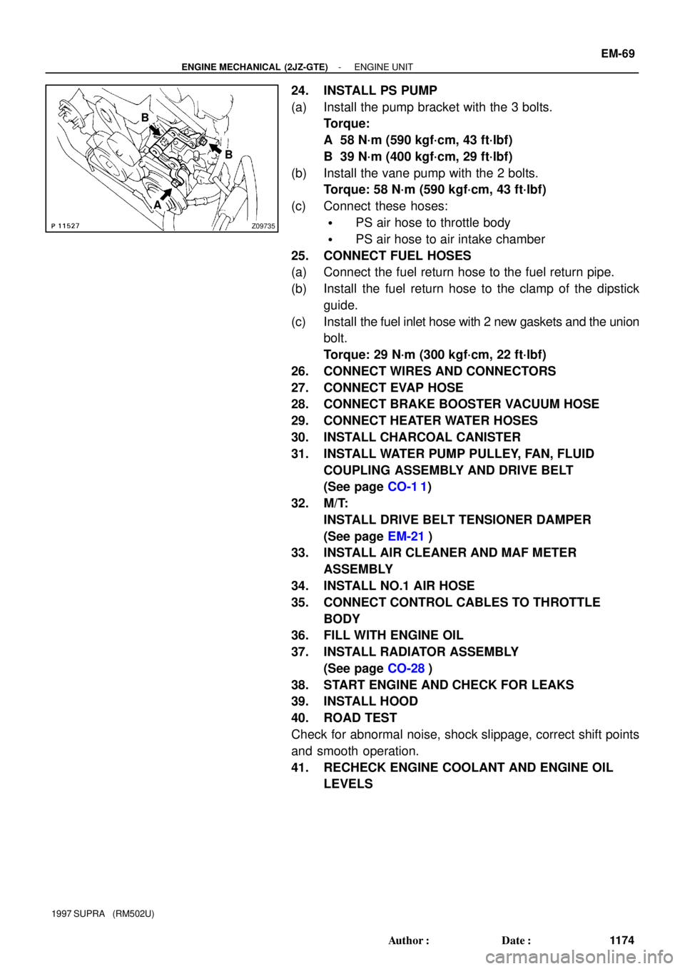
24. INSTALL PS PUMP
(a) Install the pump bracket with the 3 bolts.
Torque:
A 58 N´m (590 kgf´cm, 43 ft´lbf)
B 39 N´m (400 kgf´cm, 29 ft´lbf)
(b) Install the vane pump with the 2 bolts.
Torque: 58 N´m (590 kgf´cm, 43 ft´lbf)
(c) Connect these hoses:
�PS air hose to throttle body
�PS air hose to air intake chamber
25. CONNECT FUEL HOSES
(a) Connect the fuel return hose to the fuel return pipe.
(b) Install the fuel return hose to the clamp of the dipstick
guide.
(c) Install the fuel inlet hose with 2 new gaskets and the union
bolt.
Torque: 29 N´m (300 kgf´cm, 22 ft´lbf)
26. CONNECT WIRES AND CONNECTORS
27. CONNECT EVAP HOSE
28. CONNECT BRAKE BOOSTER VACUUM HOSE
29. CONNECT HEATER WATER HOSES
30. INSTALL CHARCOAL CANISTER
31. INSTALL WATER PUMP PULLEY, FAN, FLUID
COUPLING ASSEMBLY AND DRIVE BELT
(See page CO-1 1)
32. M/T:
INSTALL DRIVE BELT TENSIONER DAMPER
(See page EM-21)
33. INSTALL AIR CLEANER AND MAF METER
ASSEMBLY
34. INSTALL NO.1 AIR HOSE
35. CONNECT CONTROL CABLES TO THROTTLE
BODY
36. FILL WITH ENGINE OIL
37. INSTALL RADIATOR ASSEMBLY
(See page CO-28)
38. START ENGINE AND CHECK FOR LEAKS
39. INSTALL HOOD
40. ROAD TEST
Check for abnormal noise, shock slippage, correct shift points
and smooth operation.
41. RECHECK ENGINE COOLANT AND ENGINE OIL
LEVELS
Page 1323 of 1807
EM0AO-02
P02447
P04467
P12207Knock Sensor
Union for Oil Cooler HoseOil Pressure
Switch
SST
- ENGINE MECHANICAL (2JZ-GTE)CYLINDER BLOCK
EM-71
1176 Author�: Date�:
1997 SUPRA (RM502U)
DISASSEMBLY
1. M/T:
REMOVE FLYWHEEL
2. A/T:
REMOVE DRIVE PLATE
3. INSTALL ENGINE TO ENGINE STAND FOR
DISASSEMBLY
4. REMOVE GENERATOR
5. REMOVE TIMING BELT AND PULLEYS
(See page EM-15)
6. REMOVE CYLINDER HEAD (See page EM-29)
7. REMOVE OIL COOLER (See page LU-20)
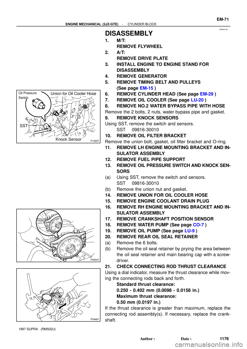
8. REMOVE NO.2 WATER BYPASS PIPE WITH HOSE
Remove the 2 bolts, 2 nuts, water bypass pipe and gasket.
9. REMOVE KNOCK SENSORS
Using SST, remove the switch and sensors.
SST 09816-30010
10. REMOVE OIL FILTER BRACKET
Remove the union bolt, gasket, oil filter bracket and O-ring.
11. REMOVE LH ENGINE MOUNTING BRACKET AND IN-
SULATOR ASSEMBLY
12. REMOVE FUEL PIPE SUPPORT
13. REMOVE OIL PRESSURE SWITCH AND KNOCK SEN-
SORS
(a) Using SST, remove the switch and sensors.
SST 09816-30010
(b) Remove the union nut and gasket.
14. REMOVE UNION FOR OIL COOLER HOSE
15. REMOVE ENGINE COOLANT DRAIN PLUG
16. REMOVE RH ENGINE MOUNTING BRACKET AND IN-
SULATOR ASSEMBLY
17. REMOVE CRANKSHAFT POSITION SENSOR
18. REMOVE WATER PUMP (See page CO-7)
19. REMOVE OIL PUMP (See page LU-9)
20. REMOVE REAR OIL SEAL RETAINER
(a) Remove the 6 bolts.
(b) Remove the oil seal retainer by prying the area between
the oil seal retainer and main bearing cap with a screw-
driver.
21. CHECK CONNECTING ROD THRUST CLEARANCE
Using a dial indicator, measure the thrust clearance while mov-
ing the connecting rods back and forth.
Standard thrust clearance:
0.250 - 0.402 mm (0.0098 - 0.0158 in.)
Maximum thrust clearance:
0.50 mm (0.0197 in.)
If the thrust clearance is greater than maximum, replace the
connecting rod assembly(s). If necessary, replace the crank-
shaft.
Page 1324 of 1807
P02436
P04469
P04599
Plastigage
P02426
EM-72
- ENGINE MECHANICAL (2JZ-GTE)CYLINDER BLOCK
1177 Author�: Date�:
1997 SUPRA (RM502U)
Connecting rod thickness:
25.898 - 25.950 mm (1.0196 - 1.0217 in.)
22. REMOVE CONNECTING ROD CAPS AND CHECK
OIL CLEARANCE
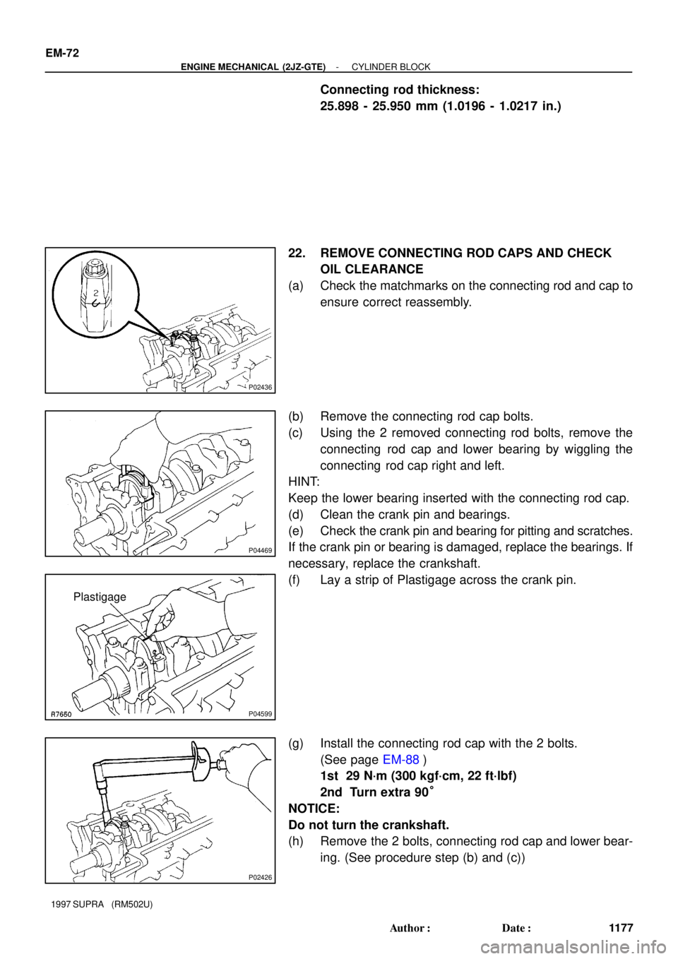
(a) Check the matchmarks on the connecting rod and cap to
ensure correct reassembly.
(b) Remove the connecting rod cap bolts.
(c) Using the 2 removed connecting rod bolts, remove the
connecting rod cap and lower bearing by wiggling the
connecting rod cap right and left.
HINT:
Keep the lower bearing inserted with the connecting rod cap.
(d) Clean the crank pin and bearings.
(e) Check the crank pin and bearing for pitting and scratches.
If the crank pin or bearing is damaged, replace the bearings. If
necessary, replace the crankshaft.
(f) Lay a strip of Plastigage across the crank pin.
(g) Install the connecting rod cap with the 2 bolts.
(See page EM-88)
1st 29 N´m (300 kgf´cm, 22 ft´lbf)
2nd Turn extra 90°
NOTICE:
Do not turn the crankshaft.
(h) Remove the 2 bolts, connecting rod cap and lower bear-
ing. (See procedure step (b) and (c))
Page 1326 of 1807
P02288
P04472
Z07401
10
11 12
13 14
5 6
7 8
1 2
3 4
9
P04471
P04792
Plastigage EM-74
- ENGINE MECHANICAL (2JZ-GTE)CYLINDER BLOCK
1179 Author�: Date�:
1997 SUPRA (RM502U)
23. REMOVE PISTON AND CONNECTING ROD
ASSEMBLIES
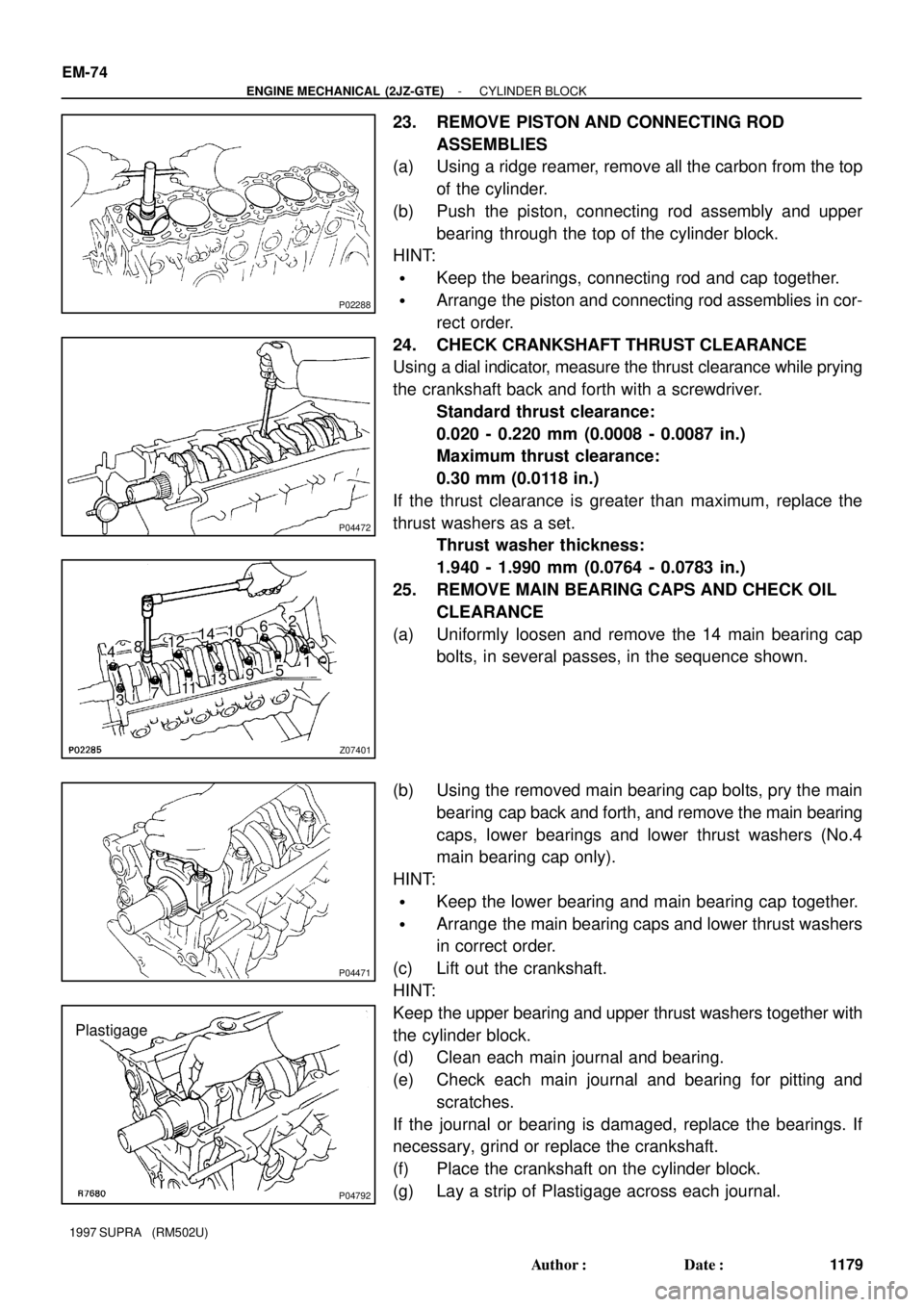
(a) Using a ridge reamer, remove all the carbon from the top
of the cylinder.
(b) Push the piston, connecting rod assembly and upper
bearing through the top of the cylinder block.
HINT:
�Keep the bearings, connecting rod and cap together.
�Arrange the piston and connecting rod assemblies in cor-
rect order.
24. CHECK CRANKSHAFT THRUST CLEARANCE
Using a dial indicator, measure the thrust clearance while prying
the crankshaft back and forth with a screwdriver.
Standard thrust clearance:
0.020 - 0.220 mm (0.0008 - 0.0087 in.)
Maximum thrust clearance:
0.30 mm (0.0118 in.)
If the thrust clearance is greater than maximum, replace the
thrust washers as a set.
Thrust washer thickness:
1.940 - 1.990 mm (0.0764 - 0.0783 in.)
25. REMOVE MAIN BEARING CAPS AND CHECK OIL
CLEARANCE
(a) Uniformly loosen and remove the 14 main bearing cap
bolts, in several passes, in the sequence shown.
(b) Using the removed main bearing cap bolts, pry the main
bearing cap back and forth, and remove the main bearing
caps, lower bearings and lower thrust washers (No.4
main bearing cap only).
HINT:
�Keep the lower bearing and main bearing cap together.
�Arrange the main bearing caps and lower thrust washers
in correct order.
(c) Lift out the crankshaft.
HINT:
Keep the upper bearing and upper thrust washers together with
the cylinder block.
(d) Clean each main journal and bearing.
(e) Check each main journal and bearing for pitting and
scratches.
If the journal or bearing is damaged, replace the bearings. If
necessary, grind or replace the crankshaft.
(f) Place the crankshaft on the cylinder block.
(g) Lay a strip of Plastigage across each journal.