Page 1330 of 1807
P02123
P02108
P02069
P02278
EM-78
- ENGINE MECHANICAL (2JZ-GTE)CYLINDER BLOCK
1183 Author�: Date�:
1997 SUPRA (RM502U)
28. CHECK FIT BETWEEN PISTON AND PISTON PIN
Try to move the piston back and forth on the piston pin.
If any movement is felt, replace the piston and pin as a set.
29. REMOVE PISTON RINGS
(a) Using a piston ring expander, remove the 2 compression
rings.
(b) Remove the 2 side rails and oil ring expander by hand.
HINT:
Arrange the piston rings in correct order only.
30. DISCONNECT CONNECTING ROD FROM PISTON
(a) Using a small screwdriver, remove the 2 snap rings.
(b) Gradually heat the piston to about 80°C (176°F).
(c) Using a plastic-faced hammer and brass bar, lightly tap
out the piston pin and remove the connecting rod.
HINT:
�The piston and pin are a matched set.
�Arrange the pistons, pins, rings, connecting rods and
bearings in the correct order.
Page 1331 of 1807

10 mm
(0.39 in) Middle A
B
C Front
- ENGINE MECHANICAL (2JZ-GTE)CYLINDER BLOCK
EM-79
1184 Author�: Date�:")
EM0AP-02
P02289
Z02380
P02286
Z00145
121
2 1Thrust
Direction
Axial
Direction
10 mm
(0.39 in)
10 mm
(0.39 in) Middle A
B
C Front
- ENGINE MECHANICAL (2JZ-GTE)CYLINDER BLOCK
EM-79
1184 Author�: Date�:
1997 SUPRA (RM502U)
INSPECTION
1. REMOVE GASKET MATERIAL
Using a gasket scraper, remove all the gasket material from the
cylinder block surface.
2. CLEAN CYLINDER BLOCK
Using a soft brush and solvent, thoroughly clean the cylinder
block.
3. INSPECT CYLINDER BLOCK SURFACE FOR
FLATNESS
Using precision straight edge and feeler gauge, measure the
surfaces of the cylinder block for warpage.
Maximum warpage: 0.07 mm (0.0028 in.)
If warpage is greater than maximum, replace the cylinder block.
4. INSPECT CYLINDER FOR VERTICAL SCRATCHES
Visually check the cylinder for vertical scratches.
If deep scratches are present, replace the cylinder block.
5. INSPECT CYLINDER BORE DIAMETER
Using a cylinder gauge, measure the cylinder bore diameter at
positions A, B and C in the thrust and axial directions.
Standard diameter:
86.000 - 86.013 mm (3.3858 - 3.3863 in.)
Maximum diameter: 86.02 mm (3.3866 in.)
If the diameter is greater than maximum, replace the cylinder
block.
Page 1334 of 1807
CYLINDER BLOCK
1187 Author�: Date�:
1997 SUPRA (RM502U)
12. PINSPECT PISTON PIN FIT
At 80°C (176°F), you should be able to pu")
P02082
Z02381
Z02382
P02275
EM0227
EM-82
- ENGINE MECHANICAL (2JZ-GTE)CYLINDER BLOCK
1187 Author�: Date�:
1997 SUPRA (RM502U)
12. PINSPECT PISTON PIN FIT
At 80°C (176°F), you should be able to push the piston pin into
the piston pin hole with your thumb.
13. INSPECT CONNECTING ROD ALIGNMENT
Using a feeler gauge and rod aligner, check the connecting rod
alignment.
�Check for out-of-alignment
Maximum out-of-alignment:
0.05 mm (0.0020 in.) per 100 mm (3.94 in.)
If out-of-alignment is greater than maximum, replace the con-
necting rod assembly.
�Check for twist
Maximum twist:
0.15 mm (0.0059 in.) per 100 mm (3.94 in.)
If twist is greater than maximum, replace the connecting rod as-
sembly.
14. INSPECT PISTON PIN OIL CLEARANCE
(a) Using a caliper gauge, measure the inside diameter of the
connecting rod bushing.
Bushing inside diameter:
22.005 - 22.014 mm (0.8663 - 0.8667 in.)
(b) Using a micrometer, measure the piston pin diameter.
Piston pin diameter:
21.997 - 22.006 mm (0.8660 - 0.8664 in.)
(c) Subtract the piston pin diameter measurement from the
bushing inside diameter measurement.
Standard oil clearance:
0.005 - 0.011 mm (0.0002 - 0.0004 in.)
Maximum oil clearance:
0.05 mm (0.0020 in.)
If the oil clearance is greater than maximum, replace the bush-
ing. If necessary, replace the piston and piston pin as a set.
Page 1335 of 1807

U/S 0.25 mm (in.)
Main journal
Crank pin61.984 - 62.000
(2.4403 - 2.4409)
51.982 - 52.000
(2.0465 - 2.0472)61.745 - 61.755
(2.4309 -")
P02143
P02459
About
20 mmCompressed
P02153
Z02383
ItemSTD mm (in.)
U/S 0.25 mm (in.)
Main journal
Crank pin61.984 - 62.000
(2.4403 - 2.4409)
51.982 - 52.000
(2.0465 - 2.0472)61.745 - 61.755
(2.4309 - 2.4313)
51.745 - 51.755
(0.0372 - 2.0376)
- ENGINE MECHANICAL (2JZ-GTE)CYLINDER BLOCK
EM-83
1188 Author�: Date�:
1997 SUPRA (RM502U)
(d) Check the piston pin fit at room temperature.
Coat the piston pin with engine oil and push it into the con-
necting rod with your thumb.
15. INSPECT CONNECTING ROD BOLTS
Using vernier calipers, measure the minimum diameter of the
compressed bolt at the measuring point.
Standard diameter: 8.1 - 8.3 mm (0.319 - 0.327 in.)
Minimum diameter: 8.0 mm (0.315 in.)
If the diameter is less than minimum, replace the connecting rod
bolt.
16. INSPECT CRANKSHAFT FOR RUNOUT
(a) Place the crankshaft on V-blocks.
(b) Using a dial indicator, measure the circle runout at the
center journal.
Maximum circle runout: 0.06 mm (0.0024 in.)
If the circle runout is greater than maximum, replace the crank-
shaft.
17. INSPECT MAIN JOURNALS AND CRANK PINS
(a) Using a micrometer, measure the diameter of each main
journal and crank pin.
Diameter:
If the diameter is not as specified, check the oil clearance. (See
page EM-71)
(b) Check each main journal and crank pin for taper and out-
of-round as shown.
Maximum taper and out-of round:
0.02 mm (0.0008 in.)
If the taper or out-of-round is greater than maximum, grind or
replace the crankshaft.
Page 1339 of 1807
EM6535
P02143
- ENGINE MECHANICAL (2JZ-GTE)CYLINDER BLOCK
EM-87
1192 Author�: Date�:
1997 SUPRA (RM502U)
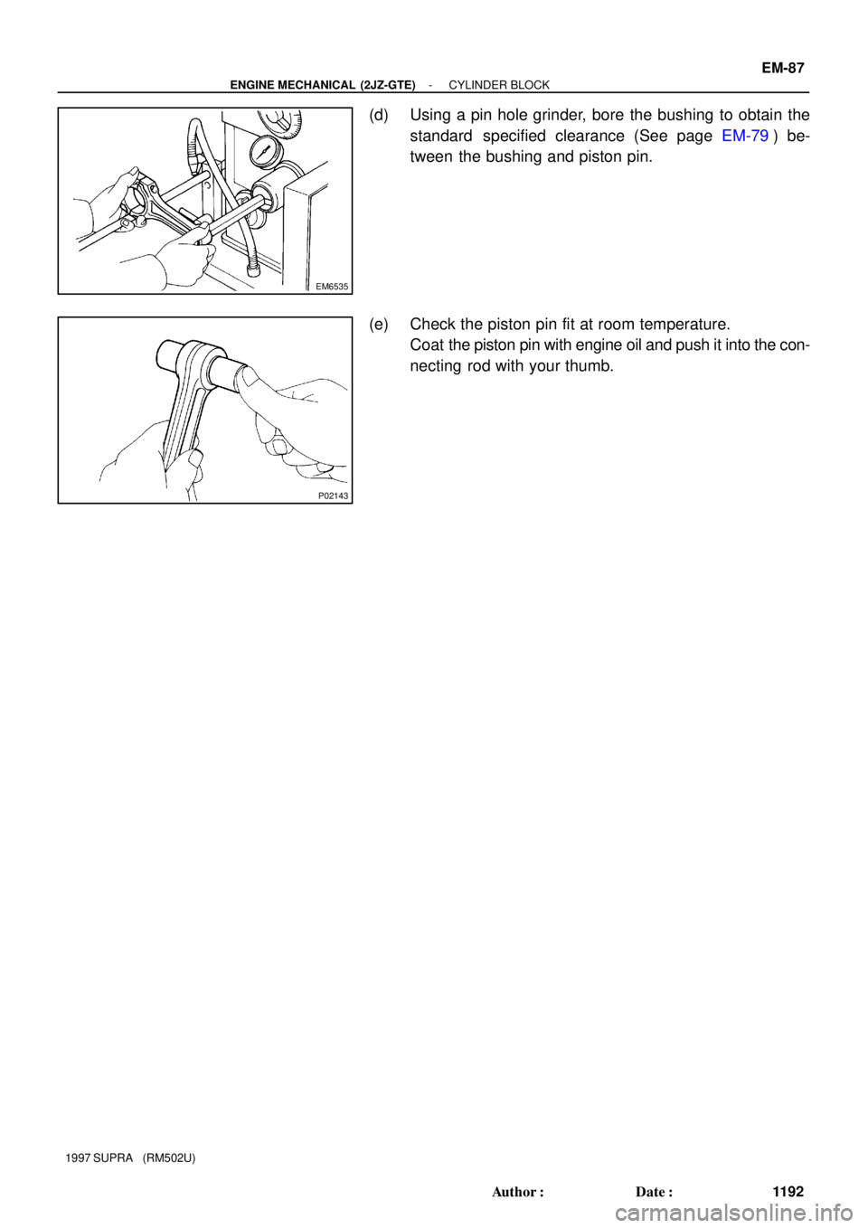
(d) Using a pin hole grinder, bore the bushing to obtain the
standard specified clearance (See page EM-79) be-
tween the bushing and piston pin.
(e) Check the piston pin fit at room temperature.
Coat the piston pin with engine oil and push it into the con-
necting rod with your thumb.
Page 1343 of 1807

Front
P04479
P02426
P02419
Painted
Mark Front
- ENGINE MECHANICAL (2JZ-GTE)CYLINDER BLOCK
EM-91
1196 Author�: Date�:
1997 SUPRA (RM502U)
(c)")
P02440
90°Painted Mark
90°
Z02418
Front Mark
(Cavity)
Front
P04479
P02426
P02419
Painted
Mark Front
- ENGINE MECHANICAL (2JZ-GTE)CYLINDER BLOCK
EM-91
1196 Author�: Date�:
1997 SUPRA (RM502U)
(c) Mark the front of the main bearing cap bolt head with
paint.
(d) Retighten the main bearing cap bolts 90° in the numerical
order shown above.
(e) Check that the painted mark is now at a 90° angle to the
front.
(f) Check that the crankshaft turns smoothly.
10. CHECK CRANKSHAFT THRUST CLEARANCE
(See page EM-71)
11. INSTALL PISTON AND CONNECTING ROD
ASSEMBLIES
Using a piston ring compressor, push the correctly numbered
piston and connecting rod assemblies into each cylinder with
the front mark of the piston facing forward.
12. PLACE CONNECTING ROD CAP ON CONNECTING
ROD
(a) Match the numbered connecting rod cap with the con-
necting rod.
(b) Install the connecting rod cap with by aligning the dowel
pin to the corresponding hole.
13. INSTALL CONNECTING ROD CAP BOLTS
HINT:
�The connecting rod cap bolts are tightened in 2 progres-
sive steps (steps (b) and (d)).
�If any of the connecting rod bolts break or deform, replace
them.
(a) Apply a light coat of engine oil on the threads and under
the heads of the connecting rod cap bolts.
(b) At first, install and alternately tighten the bolts of the con-
necting rod cap in several passes.
Torque: 29 N´m (300 kgf´cm, 22 ft´lbf)
If any one of the connecting rod cap bolts does not meet the
torque specification, replace the cap bolt.
(c) Mark the front of the connecting rod cap bolt with paint.
Page 1344 of 1807
CYLINDER BLOCK
1197 Author�: Date�:
1997 SUPRA (RM502U)
(d) Retighten")
P02420
90°Painted Mark
90°
P02197
Seal Width
2 - 3 mm
Seal
Packing
P02104
Z16761
Adhesive EM-92
- ENGINE MECHANICAL (2JZ-GTE)CYLINDER BLOCK
1197 Author�: Date�:
1997 SUPRA (RM502U)
(d) Retighten the connecting rod cap bolts 90° in the numeri-
cal order shown.
(e) Check that the painted mark is now at a 90° angle to the
front.
(f) Check that the crankshaft turns smoothly.
14. CHECK CONNECTING ROD THRUST CLEARANCE
(See page EM-79)
15. INSTALL REAR OIL SEAL RETAINER
(a) Remove any old packing (FIPG) material and be careful
not to drop any oil on the contact surfaces of the retainer
and cylinder block.
�Using a razor blade and gasket scraper, remove all
the old packing (FIPG) material from the gasket sur-
faces and sealing groove.
�Thoroughly clean all components to remove all de-
bris.
�Using a non-residue solvent, clean both sealing
surfaces.
(b) Apply seal packing to the retainer as shown in the illustra-
tion.
Seal packing:
Part No. 08826-00080 or equivalent
�Install a nozzle that has been cut to a 2 - 3 mm (0.08
- 0.12 in.) opening.
�Parts must be assembled within 3 minutes of ap-
plication. Otherwise the material must be removed
and reapplied.
�Immediately remove nozzle from the tube and rein-
stall cap.
(c) Install the retainer with the 6 bolts.
Torque: 6.0 N´m (60 kgf´cm, 53 in.´lbf)
16. INSTALL OIL PUMP (See page LU-16)
17. INSTALL WATER PUMP (See page CO-1 1)
18. INSTALL CRANKSHAFT POSITION SENSOR
Torque: 9.0 N´m (90 kgf´cm, 80 in.´lbf)
19. INSTALL RH ENGINE MOUNTING BRACKET AND
INSULATOR ASSEMBLY
Torque: 59 N´m (590 kgf´cm, 44 ft´lbf)
20. INSTALL ENGINE COOLANT DRAIN PLUG
Torque: 30 N´m (300 kgf´cm, 22 ft´lbf)
21. INSTALL UNION FOR OIL COOLER HOSE
(a) Apply adhesive to 2 or 3 threads of the union.
Adhesive:
Part No. 08833-00070, THREE BOND 1324,
or equivalent
(b) Install the union.
Torque: 40 N´m (400 kgf´cm, 30 ft´lbf)
Page 1345 of 1807
CYLINDER BLOCK
EM-93
1198 Author�: Date�:
1997 SUPRA (RM502U)
22. INSTALL OIL PRESSURE SWITCH AND KNOCK SEN-
SORS")
P10820
Adhesive
P13197
Oil Pressure
SwitchKnock Sensor
- ENGINE MECHANICAL (2JZ-GTE)CYLINDER BLOCK
EM-93
1198 Author�: Date�:
1997 SUPRA (RM502U)
22. INSTALL OIL PRESSURE SWITCH AND KNOCK SEN-
SORS
(a) Install the union nut with a new gasket.
SST 09816-30010
Torque: 55 N´m (550 kgf´cm, 41 ft´lbf)
(b) Apply adhesive to 2 or 3 threads of the oil pressure switch.
Adhesive:
Part No. 08833-00080, THREE BOND 1344,
LOCKTITE 242 or equivalent
(c) Using SST, install the switch and sensors.
SST 09816-30010
Torque:
OIl pressure switch: 14 N´m (150 kgf´cm, 11 ft´lbf)
Knock sensor: 44 N´m (450 kgf´cm, 33 ft´lbf)
23. INSTALL FUEL PIPE SUPPORT
Torque: 28 N´m (290 kgf´cm, 21 ft´lbf)
24. INSTALL LH ENGINE MOUNTING BRACKET AND IN-
SULATOR ASSEMBLY
Torque: 58 N´m (590 kgf´cm, 44 ft´lbf)
25. INSTALL OIL FILTER BRACKET
(a) Check and clean the oil filter bracket installation.
(b) Place a new O-ring in position on the oil filter bracket.
(c) Apply clean engine oil to the O-ring.
(d) Install a new gasket to the union bolt.
(e) Install the oil filter bracket with the union bolt.
Torque: 90 N´m (900 kgf´cm, 66 ft´lbf)
26. INSTALL NO.2 WATER BYPASS PIPE WITH HOSE
(a) Install a new gasket to the water pump.
(b) Install the water bypass pipe with the 2 bolts and 2 nuts.
Torque: 21 N´m (210 kgf´cm, 15 ft´lbf)
27. INSTALL OIL COOLER (See page LU-22)
28. INSTALL CYLINDER HEAD (See page EM-47)
29. INSTALL TIMING PULLEYS AND BELT (See page
EM-21)
30. INSTALL GENERATOR (See page CH-18)
31. REMOVE ENGINE STAND FROM ENGINE