Page 570 of 1807

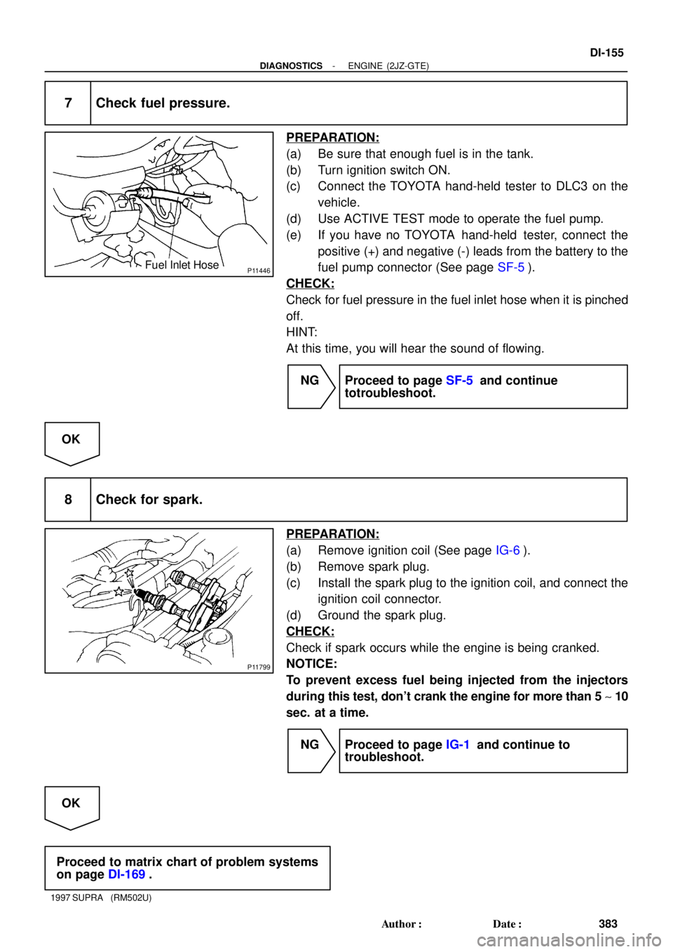
P11446Fuel Inlet Hose
P11799
- DIAGNOSTICSENGINE (2JZ-GTE)
DI-155
383 Author�: Date�:
1997 SUPRA (RM502U)
7 Check fuel pressure.
PREPARATION:
(a) Be sure that enough fuel is in the tank.
(b) Turn ignition switch ON.
(c) Connect the TOYOTA hand-held tester to DLC3 on the
vehicle.
(d) Use ACTIVE TEST mode to operate the fuel pump.
(e) If you have no TOYOTA hand-held tester, connect the
positive (+) and negative (-) leads from the battery to the
fuel pump connector (See page SF-5).
CHECK:
Check for fuel pressure in the fuel inlet hose when it is pinched
off.
HINT:
At this time, you will hear the sound of flowing.
NG Proceed to page SF-5 and continue
totroubleshoot.
OK
8 Check for spark.
PREPARATION:
(a) Remove ignition coil (See page IG-6).
(b) Remove spark plug.
(c) Install the spark plug to the ignition coil, and connect the
ignition coil connector.
(d) Ground the spark plug.
CHECK:
Check if spark occurs while the engine is being cranked.
NOTICE:
To prevent excess fuel being injected from the injectors
during this test, don't crank the engine for more than 5 ~ 10
sec. at a time.
NG Proceed to page IG-1 and continue to
troubleshoot.
OK
Proceed to matrix chart of problem systems
on page DI-169.
Page 578 of 1807
DI4SJ-01
S04073
Throttle Control ECU
VSV for Intake
Air Control Valve
(VSV1)
VSV for EXhaust
Bypass Valve
(VSV3) Heated Oxygen Sensor
(Bank 1 Sensor 1)
Ignition Coil
Mass Air Flow Meter
(Intake Air Temp. Sensor)
Engine Coolant Temp.
Sensor
VSV for Exhaust
Gas Control Valve
(VSV 2)
VSV for Waste
Gate Valve
(VSV4)VSV for EGR
ECM
IAC Valve
DLC1EGR Gas Temp. Sensor
Ignition Switch
Combination Meter
& Telltale Light RH
Fuel Pump ECU
Fuel Pump
No.1 Vehicle Speed Sensor
DLC3
Park/Neutral Position Switch
Stop Light Switch
Heated Oxygen Sensor
(Bank 1 Sensor 2) Igniter
Knock Sensor 2
Camshaft Position Sensor No.2
VSV for EVAP
Turbo Pressure Sensor
Camshaft Position Sensor No.1
Throttle Position Sensor
Sub Throttle Actuator Knock Sensor 1
Sub Throttle Position Sensor
Crankshaft Position Sensor
- DIAGNOSTICSENGINE (2JZ-GTE)
DI-163
391 Author�: Date�:
1997 SUPRA (RM502U)
PARTS LOCATION
Page 1025 of 1807
![TOYOTA SUPRA 1997 Service Repair Manual Position of Parts in Engine Compartment
[2JZ-GTE]
R 1 Radiator Fan Motor No.1
R 2 Radiator Fan Relay No.1
R 3 Radiator Fan Relay No.2
R20 Radiator Fan Motor No.2
S 1 SFI Resistor
S 2 Starter
S 3 Start TOYOTA SUPRA 1997 Service Repair Manual Position of Parts in Engine Compartment
[2JZ-GTE]
R 1 Radiator Fan Motor No.1
R 2 Radiator Fan Relay No.1
R 3 Radiator Fan Relay No.2
R20 Radiator Fan Motor No.2
S 1 SFI Resistor
S 2 Starter
S 3 Start](/manual-img/14/57469/w960_57469-1024.png)
Position of Parts in Engine Compartment
[2JZ-GTE]
R 1 Radiator Fan Motor No.1
R 2 Radiator Fan Relay No.1
R 3 Radiator Fan Relay No.2
R20 Radiator Fan Motor No.2
S 1 SFI Resistor
S 2 Starter
S 3 Starter
S 5 Sub Throttle Position Sensor
S18 Sub Throttle Valve Motor
T 1 Theft Deterrent Horn
T 2 Throttle Position Sensor
T14 Turbo Pressure Sensor
V 2 VSV (EGR)
V 3 VSV (EVAP)
V 4 VSV (Exhaust Bypass Valve)
V 5 VSV (Exhaust Gas Control Valve)
V 6 VSV (Fuel Pressure Up)
V 7 VSV (Intake Air Control Valve)
V 8 VSV (Waste Gate Valve)
V10 Vehicle Speed Sensor No.1 (Combination Meter)
V11 Vehicle Speed Sensor No.2 (Electronically
Controlled Transmission)
W 1 Washer Motor I 1 Idle AIr Control Valve
I 2 Igniter
I 3 Igniter
I 6 Ignition Coil No.1
I 7 Ignition Coil No.2
I 8 Ignition Coil No.3
I 9 Ignition Coil No.4
I10 Ignition Coil No.5
I11 Ignition Coil No.6
I12 Injector No.1
I13 Injector No.2
I14 Injector No.3
I15 Injector No.4
I16 Injector No.5
I17 Injector No.6
K 1 Knock Sensor (on Front Side)
K 2 Knock Sensor (on Rear Side)
M 1 Mass Air Flow Meter
N 1 Noise Filter
O 1 O/D Direct Clutch Speed Sensor
O 2 Oil Pressure SW
P 1 PPS Solenoid
P 2 Park/Neutral Position SW, Back-Up Light SW and
A/T Indicator Light SW (A/T)
P13 Parking Light LH
25
G
Page 1027 of 1807
![TOYOTA SUPRA 1997 Service Repair Manual 27
G
Position of Parts in Engine Compartment
[2JZ-GE]
O 2 Oil Pressure SW
P 1 PPS Solenoid
P 2 Park/Neutral Position SW, Back-Up Light SW and
A/T Indicator Light SW (A/T)
P 3 Power Steering Pressure S TOYOTA SUPRA 1997 Service Repair Manual 27
G
Position of Parts in Engine Compartment
[2JZ-GE]
O 2 Oil Pressure SW
P 1 PPS Solenoid
P 2 Park/Neutral Position SW, Back-Up Light SW and
A/T Indicator Light SW (A/T)
P 3 Power Steering Pressure S](/manual-img/14/57469/w960_57469-1026.png)
27
G
Position of Parts in Engine Compartment
[2JZ-GE]
O 2 Oil Pressure SW
P 1 PPS Solenoid
P 2 Park/Neutral Position SW, Back-Up Light SW and
A/T Indicator Light SW (A/T)
P 3 Power Steering Pressure SW
P13 Parking Light LH
S 2 Starter
S 3 Starter
T 1 Theft Deterrent Horn
T 2 Throttle Position Sensor
V 1 VSV (ACIS)
V 2 VSV (EGR)
V 3 VSV (EVAP)
V 6 VSV (Fuel Pressure Up)
V10 Vehicle Speed Sensor No.1 (Combination Meter)
V11 Vehicle Speed Sensor No.2 (Electronically
Controlled Transmission)
W 1 Washer Motor H 1 Headlight Hi LH
H 2 Headlight Hi RH
H 3 Headlight Lo LH
H 4 Headlight Lo RH
H 8 Horn LH
H 9 Horn RH
I 1 Idle Air Control Valve
I 4 Igniter
I 5 Ignition Coil
I 12 Injector No.1
I 13 Injector No.2
I 14 Injector No.3
I 15 Injector No.4
I 16 Injector No.5
I 17 Injector No.6
K 1 Knock Sensor (on Front Side)
K 2 Knock Sensor (on Rear Side)
M 1 Mass Air Flow Meter
M 2 Main Heated Oxygen Sensor (Bank 1 Sensor 1)
M 3 Main Heated Oxygen Sensor (Bank 2 Sensor 1)
N 1 Noise Filter
Page 1213 of 1807

224
COMBINATION METER
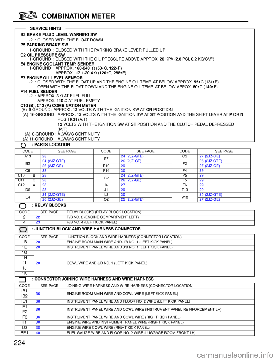
B2 BRAKE FLUID LEVEL WARNING SW
1-2 : CLOSED WITH THE FLOAT DOWN
P5 PARKING BRAKE SW
1-GROUND : CLOSED WITH THE PARKING BRAKE LEVER PULLED UP
O2 OIL PRESSURE SW
1-GROUND : CLOSED WITH THE OIL PRESSURE ABOVE APPROX. 20 KPA (2.8 PSI, 0.2 KG/CM
2)
E4 ENGINE COOLANT TEMP. SENDER
1-GROUND : APPROX. 160-240 W (50�C, 122�F)
APPROX. 17.1-20.4 W (120�C, 288�F)
E7 ENGINE OIL LEVEL SENSOR
1-2 : CLOSED WITH THE FLOAT UP AND THE ENGINE OIL TEMP. AT BELOW APPROX. 55�C (131�F)
OPEN WITH THE FLOAT DOWN AND THE ENGINE OIL TEMP. AT BELOW APPOX. 60�C (140�F)
F14 FUEL SENDER
1-2 : APPROX. 3 W AT FUEL FULL
APPROX. 110 W AT FUEL EMPTY
C10 (B), C12 (A) COMBINATION METER
(B) 9-GROUND : APPROX. 12 VOLTS WITH THE IGNITION SW AT ON POSITION
(A) 16-GROUND : APPROX. 12 VOLTS WITH THE IGNITION SW AT ST POSITION AND THE SHIFT LEVER AT P OR N
POSITION (A/T)
12 VOLTS WITH THE IGNITION SW AT ST POSITION AND THE CLUTCH PEDAL DEPRESSED
(M/T)
(A) 8-GROUND : ALWAYS CONTINUITY
(A) 11-GROUND : ALWAYS CONTINUITY
: PARTS LOCATION
CODESEE PAGECODESEE PAGECODESEE PAGE
A1328E724 (2JZ-GTE)O227 (2JZ-GE)
B224 (2JZ-GTE)E726 (2JZ-GE)P225 (2JZ-GTE)B226 (2JZ-GE)E1029P227 (2JZ-GE)
C928F1430P429
C10B28G224 (2JZ-GTE)P529
C11C28G226 (2JZ-GE)T529
C12A28I427T629
D628J129T1329
E424 (2JZ-GTE)L230V1025 (2JZ-GTE)E426 (2JZ-GE)O225 (2JZ-GTE)V1027 (2JZ-GE)
: RELAY BLOCKS
CODESEE PAGERELAY BLOCKS (RELAY BLOCK LOCATION)
222R/B NO. 2 (ENGINE COMPARTMENT LEFT)
423R/B NO. 4 (LEFT KICK PANEL)
: JUNCTION BLOCK AND WIRE HARNESS CONNECTOR
CODESEE PAGEJUNCTION BLOCK AND WIRE HARNESS (CONNECTOR LOCATION)
1B20ENGINE ROOM MAIN WIRE AND J/B NO. 1 (LEFT KICK PANEL)
1E20INSTRUMENT PANEL WIRE AND J/B NO. 1 (LEFT KICK PANEL)
1G
1H
1I20COWL WIRE AND J/B NO. 1 (LEFT KICK PANEL)
1J
()
1K
: CONNECTOR JOINING WIRE HARNESS AND WIRE HARNESS
CODESEE PAGEJOINING WIRE HARNESS AND WIRE HARNESS (CONNECTOR LOCATION)
IB136ENGINE ROOM MAIN WIRE AND COWL WIRE (LEFT KICK PANEL)IB236ENGINE ROOM MAIN WIRE AND COWL WIRE (LEFT KICK PANEL)
IE136INSTRUMENT PANEL WIRE AND FLOOR NO. 2 WIRE (LEFT KICK PANEL)
IF136INSTRUMENT PANEL WIRE AND COWL WIRE (INSTRUMENT PANEL REINFORCEMENT LH)IF236INSTRUMENT PANEL WIRE AND COWL WIRE (INSTRUMENT PANEL REINFORCEMENT LH)
IF336INSTRUMENT PANEL WIRE AND COWL WIRE (RIGHT KICK PANEL)
II138ENGINE WIRE AND INSTRUMENT PANEL WIRE (RIGHT KICK PANEL)
IJ238ENGINE WIRE COWL WIRE (RIGHT KICK PANEL)
BP140FUEL GAUGE WIRE AND FLOOR NO. 2 WIRE (LUGGAGE ROOM FRONT LH)
SERVICE HINTS
Page 1287 of 1807

EM0AJ-02
P02137
P02110
P02131
P02128
P02072
- ENGINE MECHANICAL (2JZ-GTE)CYLINDER HEAD
EM-35
1140 Author�: Date�:
1997 SUPRA (RM502U)
INSPECTION
1. CLEAN TOP SURFACES OF PISTONS AND CYL-
INDER BLOCK
(a) Turn the crankshaft, and bring each piston to top dead
center (TDC). Using a gasket scraper, remove all the car-
bon from the piston top surface.
(b) Using a gasket scraper, remove all the gasket material
from the top surface of the cylinder block.
(c) Using compressed air, blow carbon and oil from the bolt
holes.
CAUTION:
Protect your eyes when using high pressure-compressed
air.
2. REMOVE GASKET MATERIAL
Using a gasket scraper, remove all the gasket material from the
cylinder block surface.
NOTICE:
Be careful not to scratch the cylinder block contact sur-
face.
3. CLEAN COMBUSTION CHAMBERS
Using a wire brush, remove all the carbon from the combustion
chambers.
NOTICE:
Be careful not to scratch the cylinder block contact sur-
face.
4. CLEAN VALVE GUIDE BUSHINGS
Using a valve guide bushing brush and solvent, clean all the
guide bushings.
Page 1351 of 1807

EM0A8-02
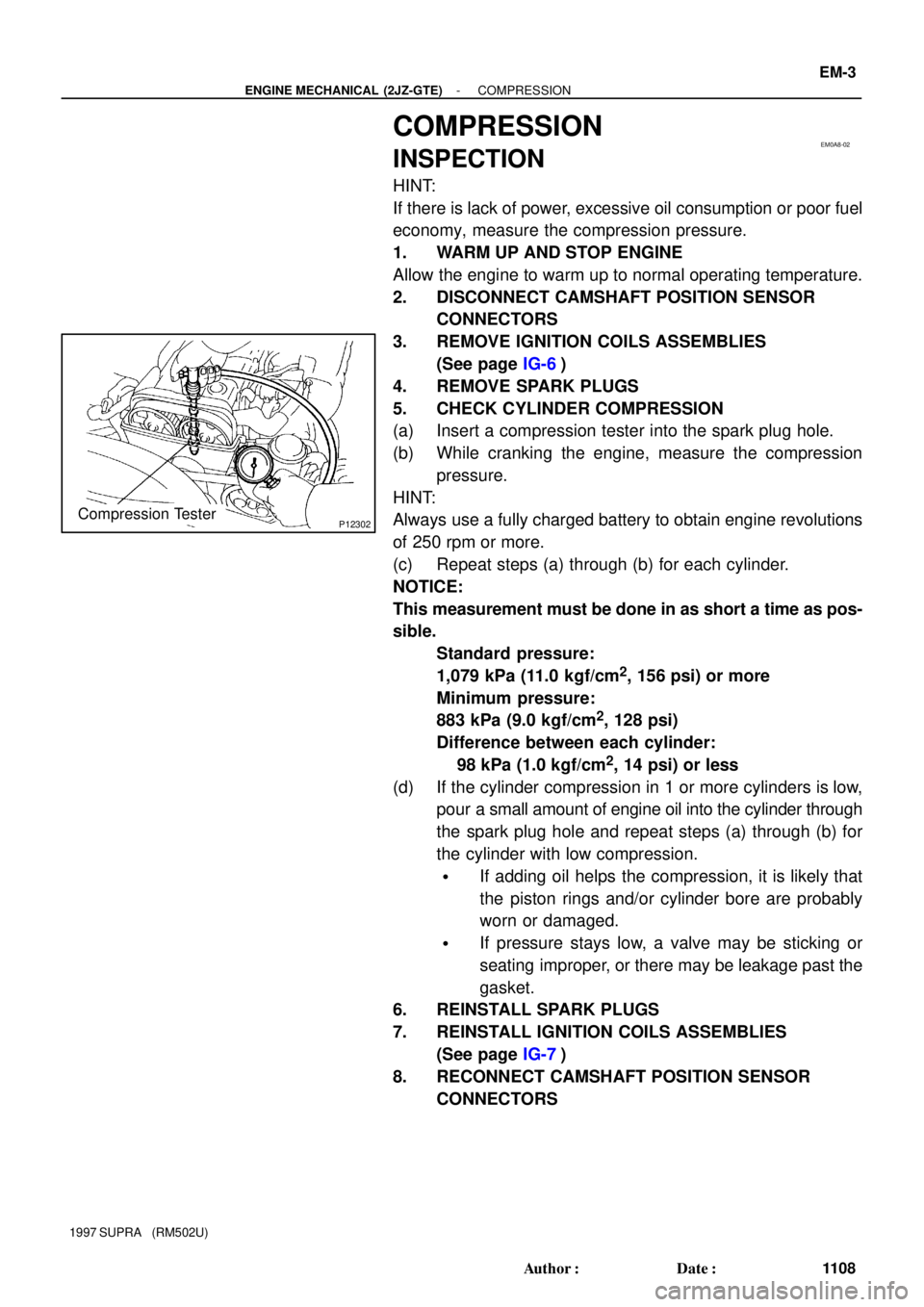
P12302Compression Tester
- ENGINE MECHANICAL (2JZ-GTE)COMPRESSION
EM-3
1108 Author�: Date�:
1997 SUPRA (RM502U)
COMPRESSION
INSPECTION
HINT:
If there is lack of power, excessive oil consumption or poor fuel
economy, measure the compression pressure.
1. WARM UP AND STOP ENGINE
Allow the engine to warm up to normal operating temperature.
2. DISCONNECT CAMSHAFT POSITION SENSOR
CONNECTORS
3. REMOVE IGNITION COILS ASSEMBLIES
(See page IG-6)
4. REMOVE SPARK PLUGS
5. CHECK CYLINDER COMPRESSION
(a) Insert a compression tester into the spark plug hole.
(b) While cranking the engine, measure the compression
pressure.
HINT:
Always use a fully charged battery to obtain engine revolutions
of 250 rpm or more.
(c) Repeat steps (a) through (b) for each cylinder.
NOTICE:
This measurement must be done in as short a time as pos-
sible.
Standard pressure:
1,079 kPa (11.0 kgf/cm
2, 156 psi) or more
Minimum pressure:
883 kPa (9.0 kgf/cm
2, 128 psi)
Difference between each cylinder:
98 kPa (1.0 kgf/cm
2, 14 psi) or less
(d) If the cylinder compression in 1 or more cylinders is low,
pour a small amount of engine oil into the cylinder through
the spark plug hole and repeat steps (a) through (b) for
the cylinder with low compression.
�If adding oil helps the compression, it is likely that
the piston rings and/or cylinder bore are probably
worn or damaged.
�If pressure stays low, a valve may be sticking or
seating improper, or there may be leakage past the
gasket.
6. REINSTALL SPARK PLUGS
7. REINSTALL IGNITION COILS ASSEMBLIES
(See page IG-7)
8. RECONNECT CAMSHAFT POSITION SENSOR
CONNECTORS
Page 1369 of 1807

P12279
P12303
Oil Pressure
Switch
SST
P12301
Oil Pressure Gauge LU-2
- LUBRICATIONOIL AND FILTER
1449 Author�: Date�:
1997 SUPRA (RM502U)
7. DISCONNECT A/C COMPRESSOR FROM ENGINE
(a) Remove the 4 bolts and nut.
(b) Using a torx socket (E10), remove the stud bolt.
(c) Disconnect the compressor connector.
(d) Remove 4 bolts and pull the compressor downward.
8. REMOVE OIL PRESSURE SWITCH, AND INSTALL OIL
PRESSURE GAUGE
(a) Disconnect the oil pressure switch connector.
(b) Using SST, remove the oil pressure switch.
SST 09816-30010
(c) Install an oil pressure gauge.
9. REINSTALL A/C COMPRESSOR
(a) Temporarily install the A/C compressor with the 4 bolts.
(b) Connect the compressor connector.
(c) Install the compressor with the stud bolts, 4 bolts and nut.
Torque:
Stud bolt: 26 N´m (265 kgf´cm, 19 ft´lbf)
Bolt and nut: 52 N´m (530 kgf´cm, 38 ft´lbf)
10. REINSTALL DRIVE BELT
Install the drive belt by turning the drive belt tensioner clock-
wise.
11. WARM UP ENGINE
Allow the engine to warm up to normal operating temperature.
12. CHECK OIL PRESSURE
Oil pressure:
At idle
49 kPa (0.5 kgf/cm
2, 7.1 psi) or more
At 3,000 rpm (2JZ-GE) or 4,000 rpm (2JZ-GTE)
324 - 579 kPa
(3.3 - 5.9 kgf/cm
2, 47 - 84 psi)
13. REMOVE DRIVE BELT
14. DISCONNECT A/C COMPRESSOR FROM ENGINE