Page 1409 of 1807

IG0152
P11795
Ohmmeter
P12177
Ohmmeter
- IGNITION (2JZ-GTE)IGNITION SYSTEM
IG-3
1497 Author�: Date�:
1997 SUPRA (RM502U)
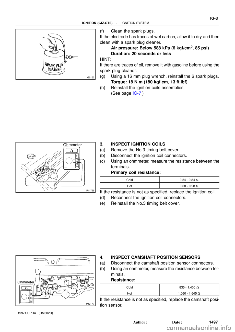
(f) Clean the spark plugs.
If the electrode has traces of wet carbon, allow it to dry and then
clean with a spark plug cleaner.
Air pressure: Below 588 kPa (6 kgf/cm
2, 85 psi)
Duration: 20 seconds or less
HINT:
If there are traces of oil, remove it with gasoline before using the
spark plug cleaner.
(g) Using a 16 mm plug wrench, reinstall the 6 spark plugs.
Torque: 18 N´m (180 kgf´cm, 13 ft´lbf)
(h) Reinstall the ignition coils assemblies.
(See page IG-7)
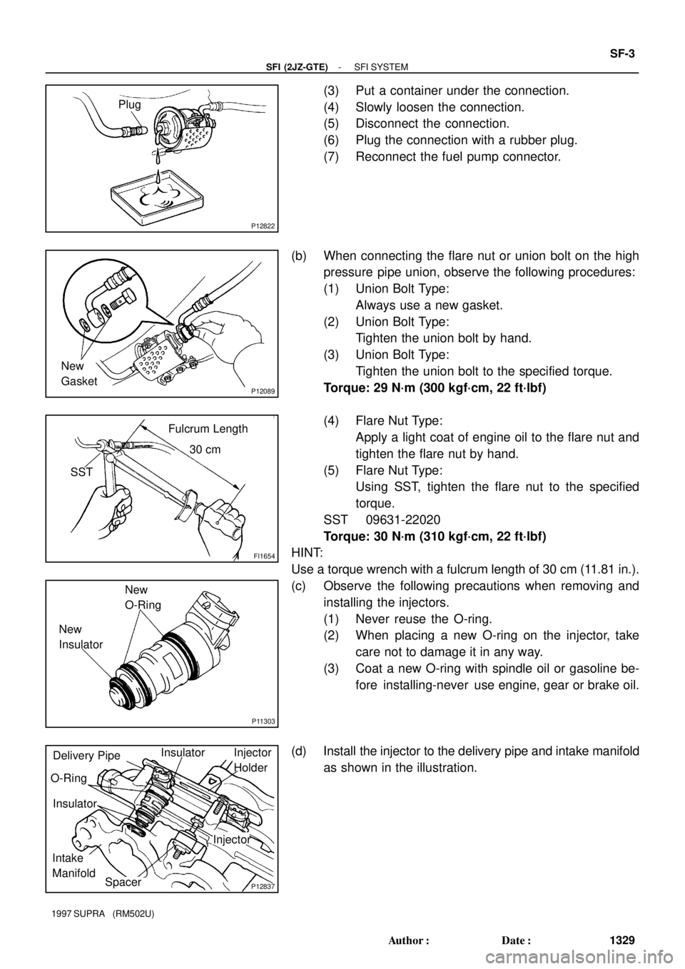
3. INSPECT IGNITION COILS
(a) Remove the No.3 timing belt cover.
(b) Disconnect the ignition coil connectors.
(c) Using an ohmmeter, measure the resistance between the
terminals.
Primary coil resistance:
Cold0.54 - 0.84 W
Hot0.68 - 0.98 W
If the resistance is not as specified, replace the ignition coil.
(d) Reconnect the ignition coil connectors.
(e) Reinstall the No.3 timing belt cover.
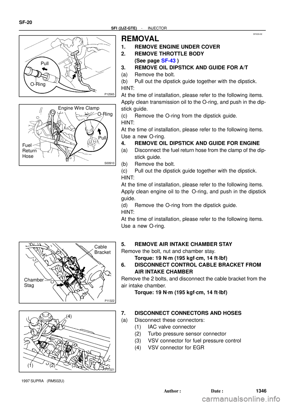
4. INSPECT CAMSHAFT POSITION SENSORS
(a) Disconnect the camshaft position sensor connectors.
(b) Using an ohmmeter, measure the resistance between ter-
minals.
Resistance:
Cold835 - 1,400 W
Hot1,060 - 1,645 W
If the resistance is not as specified, replace the camshaft posi-
tion sensor.
Page 1419 of 1807

MA01D-01
- MAINTENANCEOUTSIDE VEHICLE
MA-1
38 Author�: Date�:
1997 SUPRA (RM502U)
OUTSIDE VEHICLE
GENERAL MAINTENANCE
These are maintenance and inspection items which are considered to be the owner's responsibility.
They can be done by the owner or they can have them done at a service shop.
These items include those which should be checked on a daily basis, those which, in most cases, do not
require (special) tools and those which are considered to be reasonable for the owner to do.
Items and procedures for general maintenance are as follows.
1. GENERAL NOTES
�Maintenance items may vary from country to country. Check the owner's manual supplement in which
the maintenance schedule is shown.
�Every service item in the periodic maintenance schedule must be performed.
�Periodic maintenance service must be performed according to whichever interval in the periodic main-
tenance schedule occurs first, the odometer reading (miles) or the time interval (months).
�Maintenance service after the last period should be performed at the same interval as before unless
otherwise noted.
�Failure to do even one item an cause the engine to run poorly and increase exhaust emissions.
2. TIRES
(a) Check the pressure with a gauge. If necessary, adjust.
(b) Check for cuts, damage, uneven or excessive wear.
3. WHEEL NUTS
When checking the tires, check the nuts for looseness or for missing nuts. If necessary, tighten them.
4. WINDSHIELD WIPER BLADES
Check for wear or cracks whenever they do not wipe clean. If necessary, replace.
5. FLUID LEAKS
(a) Check underneath for leaking fuel, oil, water or other fluid.
(b) If you smell gasoline fumes or notice any leak, have the cause found and corrected.
6. DOORS AND ENGINE HOOD
(a) Check that all doors and the tailgate operate smoothly, and that all latches lock securely.
(b) Check that the engine hood secondary latch secures the hood from opening when the primary latch
is released.
Page 1463 of 1807

P12822
Plug
P12089
New
Gasket
FI1654
Fulcrum Length
30 cm
SST
P11303
New
O-Ring
New
Insulator
P12837
Delivery Pipe
O-Ring
Insulator
Intake
ManifoldInjector
Holder
Injector
SpacerInsulator
- SFI (2JZ-GTE)SFI SYSTEM
SF-3
1329 Author�: Date�:
1997 SUPRA (RM502U)
(3) Put a container under the connection.
(4) Slowly loosen the connection.
(5) Disconnect the connection.
(6) Plug the connection with a rubber plug.
(7) Reconnect the fuel pump connector.
(b) When connecting the flare nut or union bolt on the high
pressure pipe union, observe the following procedures:
(1) Union Bolt Type:
Always use a new gasket.
(2) Union Bolt Type:
Tighten the union bolt by hand.
(3) Union Bolt Type:
Tighten the union bolt to the specified torque.
Torque: 29 N´m (300 kgf´cm, 22 ft´lbf)
(4) Flare Nut Type:
Apply a light coat of engine oil to the flare nut and
tighten the flare nut by hand.
(5) Flare Nut Type:
Using SST, tighten the flare nut to the specified
torque.
SST 09631-22020
Torque: 30 N´m (310 kgf´cm, 22 ft´lbf)
HINT:
Use a torque wrench with a fulcrum length of 30 cm (11.81 in.).
(c) Observe the following precautions when removing and
installing the injectors.
(1) Never reuse the O-ring.
(2) When placing a new O-ring on the injector, take
care not to damage it in any way.
(3) Coat a new O-ring with spindle oil or gasoline be-
fore installing-never use engine, gear or brake oil.
(d) Install the injector to the delivery pipe and intake manifold
as shown in the illustration.
Page 1479 of 1807

SF0GS-02
P12565
Pull
O-Ring
S00910
Engine Wire Clamp
O-Ring
Pull
Fuel
Return
Hose
P11322
Chamber
StagCable
Bracket
P11321(1) (2) (3)(4) SF-20
- SFI (2JZ-GTE)INJECTOR
1346 Author�: Date�:
1997 SUPRA (RM502U)
REMOVAL
1. REMOVE ENGINE UNDER COVER
2. REMOVE THROTTLE BODY
(See page SF-43)
3. REMOVE OIL DIPSTICK AND GUIDE FOR A/T
(a) Remove the bolt.
(b) Pull out the dipstick guide together with the dipstick.
HINT:
At the time of installation, please refer to the following items.
Apply clean transmission oil to the O-ring, and push in the dip-
stick guide.
(c) Remove the O-ring from the dipstick guide.
HINT:
At the time of installation, please refer to the following items.
Use a new O-ring.
4. REMOVE OIL DIPSTICK AND GUIDE FOR ENGINE
(a) Disconnect the fuel return hose from the clamp of the dip-
stick guide.
(b) Remove the bolt.
(c) Pull out the dipstick guide together with the dipstick.
HINT:
At the time of installation, please refer to the following items.
Apply clean engine oil to the O-ring, and push in the dipstick
guide.
(d) Remove the O-ring from the dipstick guide.
HINT:
At the time of installation, please refer to the following items.
Use a new O-ring.
5. REMOVE AIR INTAKE CHAMBER STAY
Remove the bolt, nut and chamber stay.
Torque: 19 N´m (195 kgf´cm, 14 ft´lbf)
6. DISCONNECT CONTROL CABLE BRACKET FROM
AIR INTAKE CHAMBER
Remove the 2 bolts, and disconnect the cable bracket from the
air intake chamber.
Torque: 19 N´m (195 kgf´cm, 14 ft´lbf)
7. DISCONNECT CONNECTORS AND HOSES
(a) Disconnect these connectors:
(1) IAC valve connector
(2) Turbo pressure sensor connector
(3) VSV connector for fuel pressure control
(4) VSV connector for EGR
Page 1594 of 1807
Z19281
2JZ-GE and 2JZ-GTE:
Reservoir Cap2JZ-GE:
Oil Reservoir
2JZ-GTE:
Suction Port Union
� O-Ring
Flow Control Valve
Pressure Port
Union Front Housing
Vane Pump Shaft
2JZ-GE:
Vane Pump Pulley� O-Ring
� Bearing� Oil Seal� Gasket
Spring
� O-Ring
� Snap Ring
� Snap Ring
� O-Ring
� Straight Pin
Rear Housing Wave Washer
Side Plate
Cam Ring
Vane Plate Vane Pump Rotorx10
� Straight Pin
� Non-reusable part
: Power steering fluid
- STEERINGPOWER STEERING VANE PUMP
SR-25
1909 Author�: Date�:
1997 SUPRA (RM502U)
Page 1596 of 1807

SR145-01
R06768
SST
R01151
Z06059
Vinyl Tape
- STEERINGPOWER STEERING VANE PUMP
SR-27
1911 Author�: Date�:
1997 SUPRA (RM502U)
DISASSEMBLY
NOTICE:
When using a vise, do not overtighten it.
1. 2JZ-GE:
REMOVE VANE PUMP PULLEY
Using SST to stop the pulley rotating, remove the pulley set nut.
SST 09960-10010 (09962-01000, 09963-01000)
2. MEASURE PS VANE PUMP ROTATING TORQUE
(a) Check that the pump rotates smoothly without abnormal
noise.
(b) Temporarily install the pulley set nut, and using a torque
wrench, check the pump rotating torque.
Rotating torque:
0.2 N´m (2.5 kgf´cm, 2.2 in.´lbf) or less
3. 2JZ-GE:
REMOVE OIL RESERVOIR
(a) Remove the 3 bolts.
(b) Remove the O-ring from the reservoir.
4. 2JZ-GTE:
REMOVE SUCTION PORT UNION
(a) Remove the bolt.
(b) Remove the O-ring from the union.
5. REMOVE PRESSURE PORT UNION, FLOW CONTROL
VALVE AND SPRING
Remove the O-ring from the union.
6. REMOVE REAR HOUSING
Remove the 2 bolts.
7. REMOVE CAM RING, VANE PUMP ROTOR AND 10
VANE PLATES
NOTICE:
Be careful not to drop the vane plates.
8. REMOVE 2 STRAIGHT PINS
9. REMOVE GASKET
10. REMOVE VANE PUMP SHAFT WITH BEARING
(a) Using snap ring pliers, remove the snap ring from the front
housing.
(b) Wind vinyl tape on the serrated part of the shaft.
(c) Using a press, press out the shaft with the bearing.
Page 1602 of 1807

R01174
R06769
SST
- STEERINGPOWER STEERING VANE PUMP
SR-33
1917 Author�: Date�:
1997 SUPRA (RM502U)
9. INSTALL WAVE WASHER
Install the washer so that its protrusions fit into the slots in the
side plate.
10. INSTALL REAR HOUSING
(a) Coat 2 new O-rings with power steering fluid and install
them to the housing.
(b) Torque the 2 bolts.
Torque: 17 N´m (170 kgf´cm, 12 ft´lbf)
11. INSTALL SPRING, FLOW CONTROL VALVE AND
PRESSURE PORT UNION
(a) Coat a new O-ring with power steering fluid and install it
to the union.
(b) Torque the union.
Torque: 83 N´m (850 kgf´cm, 61 ft´lbf)
12. 2JZ-GTE:
INSTALL SUCTION PORT UNION
(a) Coat a new O-ring with power steering fluid and install it
to the union.
(b) Torque the bolt.
Torque: 13 N´m (130 kgf´cm, 9 ft´lbf)
13. 2JZ-GE:
INSTALL OIL RESERVOIR
(a) Coat a new O-ring with power steering fluid and install it
to the reservoir.
(b) Torque the 3 bolts.
Torque:
Front side bolt: 13 N´m (130 kgf´cm, 9 ft´lbf)
Rear side bolts: 17 N´m (170 kgf´cm, 12 ft´lbf)
14. MEASURE PS VANE PUMP ROTATING TORQUE
(See page SR-27)
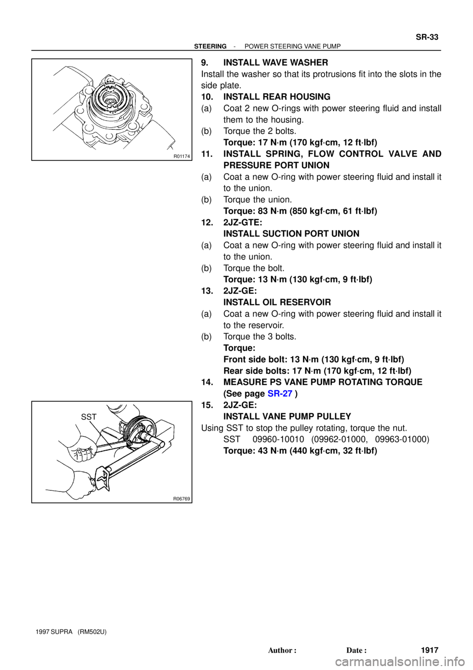
15. 2JZ-GE:
INSTALL VANE PUMP PULLEY
Using SST to stop the pulley rotating, torque the nut.
SST 09960-10010 (09962-01000, 09963-01000)
Torque: 43 N´m (440 kgf´cm, 32 ft´lbf)
Page:
< prev 1-8 9-16 17-24