Page 913 of 3342
G3M0488
14. Differential Case Assembly
A: DISASSEMBLY
1) Using a press and ST, remove the taper roller bearing.
ST 498077000 REMOVER
CAUTION:
Be careful not to damage the speedometer drive gear.
G3M0489
2) Secure the case in a vise and remove the crown gear
tightening bolts, then separate the crown gear, case (RH)
and case (LH).
G3M0490
3) Pull out the straight pin and shaft, and remove the dif-
ferential bevel gear, washer, and differential bevel pinion.
B: INSPECTION
Check each component for harmful cuts, damage and
other faults.
G3M0490
C: ASSEMBLY
1) Install the washer, differential bevel gear and differen-
tial bevel pinion in the differential case (RH). Insert the
pinion shaft, and fit the straight pin.
NOTE:
Install straight pin from reverse direction.
107
3-2SERVICE PROCEDURE
14. Differential Case Assembly
Page 914 of 3342
G3M0489
2) Install the washer and differential bevel gear to the dif-
ferential case (LH). Then put the case over the differential
case (RH), and connect both cases.
3) Install the crown gear and secure by tightening the bolt.
Standard tightening torque:
62±5 N⋅m (6.3±0.5 kg-m, 45.6±3.6 ft-lb)
G3M0491
4) Measurement of backlash (Selection of washer)
Measure the gear backlash with ST1 and ST2, and insert
ST2 through the access window of the case.
ST1 498247001 MAGNET BASE
ST2 498247100 DIAL GAUGE
Standard value:
0.13—0.18 mm (0.0051—0.0071 in)
NOTE:
Measure the backlash by applying a pinion tooth between
two bevel gear teeth.
G3M0492
5) Install the speedometer drive gear. Then force-fit the
taper roller bearing with a press and ST.
ST 398487700 DRIFT
CAUTION:
Be sure to position correctly the locking end of the
speedometer drive gear.
108
3-2SERVICE PROCEDURE
14. Differential Case Assembly
Page 928 of 3342
G3M0854
(7) Apply the automatic transmission fluid (ATF) onto
the parts immediately prior to assembly, and the speci-
fied tightening torque should be observed carefully.
(8) Use vaseline if it is necessary to hold parts in the
position when assembling.
(9) Drain ATF and differential gear oil into a saucer so
that the conditions of fluid and oil can be inspected.
(10) Do not support axle drive shaft, stator shaft, input
shaft or various pipes when moving transmission from
one place to another.
(11) Always discard old oil seals and O-ring, and install
new ones.
(12) Do not reuse old aluminum (overrunning clutch
pipes, etc.) pipes, gaskets, spring pins. Install new
ones.
(13) Be sure to replace parts which are damaged,
worn, scratched, discolored, etc.
22
3-2SERVICE PROCEDURE
1. Precaution
Page 930 of 3342
 Ensure the vehicle is in safe condition.
NOTE:
Do not check the oil level nor add oil to the case with the
front end of the vehicle jacked-up; this will resul")
G3M0283
2. DIFFERENTIAL GEAR OIL LEVEL
1) Ensure the vehicle is in safe condition.
NOTE:
Do not check the oil level nor add oil to the case with the
front end of the vehicle jacked-up; this will result in an
incorrect reading of the oil level.
2) Check whether the oil level is between the upper (F)
and lower (L) marks. If it is below the lower limit mark, add
oil until the level reaches the upper mark.
G3M0854
3. OIL LEAKAGE
It is difficult to accurately determine the precise position of
a oil leak, since the surrounding area also becomes wet
with oil. The places where oil seals and gaskets are used
are as follows:
Jointing portion of the case
�Transmission case and oil pump housing jointing portion
�Torque converter clutch case and oil pump housing joint-
ing portion
�Transmission case and transmission cover jointing por-
tion (FWD)
�Transmission case and extension case jointing portion
(AWD)
G3M0855
Torque converter clutch case
�Engine crankshaft oil seal
�Torque converter clutch impeller sleeve oil seal
�ATF cooler pipe connector
�Torque converter clutch
�Torque converter clutch case
�Axle shaft oil seal
�O-ring on the outside diameter of axle shaft oil seal
holder
�O-ring on the differential oil gauge
�Differential oil drain plug
�Speedometer cable mounting portion
�Location of steel balls
24
3-2SERVICE PROCEDURE
2. On-Car Service
Page 931 of 3342
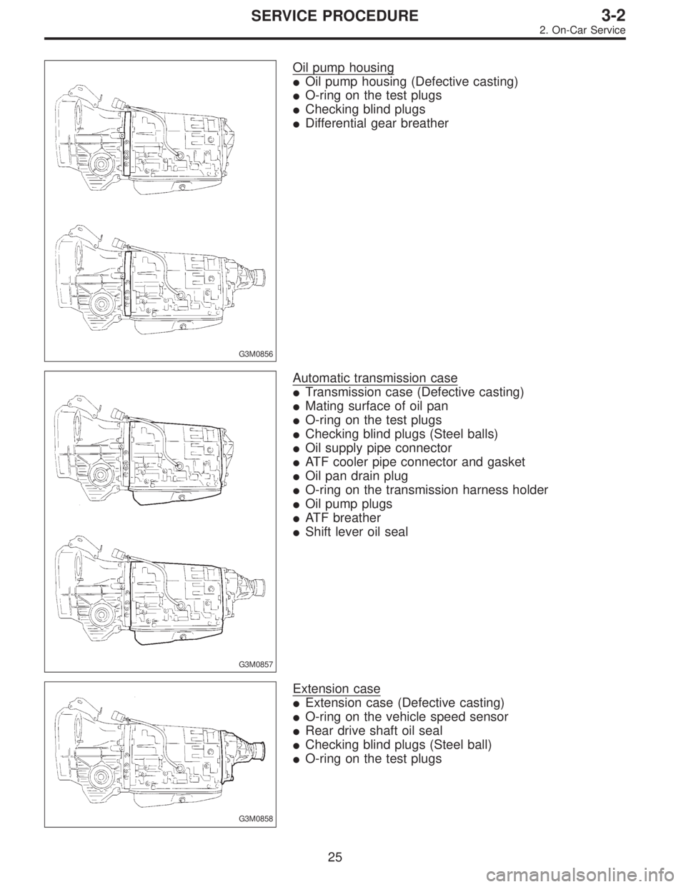
G3M0856
Oil pump housing
�Oil pump housing (Defective casting)
�O-ring on the test plugs
�Checking blind plugs
�Differential gear breather
G3M0857
Automatic transmission case
�Transmission case (Defective casting)
�Mating surface of oil pan
�O-ring on the test plugs
�Checking blind plugs (Steel balls)
�Oil supply pipe connector
�ATF cooler pipe connector and gasket
�Oil pan drain plug
�O-ring on the transmission harness holder
�Oil pump plugs
�ATF breather
�Shift lever oil seal
G3M0858
Extension case
�Extension case (Defective casting)
�O-ring on the vehicle speed sensor
�Rear drive shaft oil seal
�Checking blind plugs (Steel ball)
�O-ring on the test plugs
25
3-2SERVICE PROCEDURE
2. On-Car Service
Page 940 of 3342
G3M0304
2. DUTY SOLENOID C AND TRANSFER VALVE BODY
1) Removal
(1) Remove pitching stopper.
G3M0297
(2) Raise vehicle and drain ATF.
G3M0305
(3) Remove front exhaust pipe.
Disconnect oxygen sensor connector, and remove
exhaust pipe.
G3M0782
(4) Remove propeller shaft.
NOTE:
Before removing propeller shaft, scribe matching marks on
propeller shaft and rear differential coupling.
G3M0306
(5) Remove rear crossmember.
�Support transmission using a transmission jack and
raise slightly.
�Remove bolts and nuts as shown in Figure.
34
3-2SERVICE PROCEDURE
2. On-Car Service
Page 943 of 3342
G3M0782
(5) Install propeller shaft.
Tightening torque:
At rear differential
23±5 N⋅m (2.3±0.5 kg-m, 16.6±3.6 ft-lb)
At center bearing
39±5 N⋅m (4.0±0.5 kg-m, 28.9±3.6 ft-lb)
NOTE:
Align matching marks on propeller shaft and rear differen-
tial coupling.
G3M0305
(6) Install front exhaust pipe
Tightening torque:
At engine
29±5 N⋅m (3.0±0.5 kg-m, 21.7±3.6 ft-lb)
At hanger
29±5 N⋅m (3.0±0.5 kg-m, 21.7±3.6 ft-lb)
At front and rear connections
18±5 N⋅m (1.8±0.5 kg-m, 13.0±3.6 ft-lb)
G3M0313
(7) Lower and remove jack.
(8) Connect the following parts:
�Oxygen sensor connector
�Multi-connector
G3M0304
(9) Install pitching stopper.
Tightening torque:
Body side
57±10 N⋅m (5.8±1.0 kg-m, 42±7 ft-lb)
Engine side
49±5 N⋅m (5.0±0.5 kg-m, 36.2±3.6 ft-lb)
G3M0282
(10) Replenish ATF and check oil level. Check for
leaks.
37
3-2SERVICE PROCEDURE
2. On-Car Service
Page 944 of 3342

3. Performance Test
A: STALL TEST
1. GENERAL
The stall test is of extreme importance in diagnosing the
condition of the automatic transmission and the engine. It
should be conducted to measure the engine stall speeds in
all shift ranges except the P and N ranges.
Purposes of the stall test:
1) To check the operation of the automatic transmission
clutch.
2) To check the operation of the torque converter clutch.
3) To check engine performance.
2. TEST METHODS
Preparations before test:
�
1Check that throttle valve opens fully.
�
2Check that engine oil level is correct.
�
3Check that coolant level is correct.
�
4Check that ATF level is correct.
�
5Check that differential gear oil level is correct.
�
6Increase ATF temperature to 50 to 80°C (122 to 176°F)
by idling the engine for approximately 30 minutes (with
select lever set to“N”or“P”).
1) Install an engine tachometer at a location visible from
the driver’s compartment and mark the stall speed range
on the tachometer scale.
2) Place the wheel chocks at the front and rear of all
wheels and engage the parking brake.
3) Move the manual linkage to ensure it operates properly,
and shift the select lever to the 2 range.
B3M0286B
4) While forcibly depressing the foot brake pedal, gradu-
ally depress the accelerator pedal until the engine operates
at full throttle.
5) When the engine speed is stabilized, read that speed
quickly and release the accelerator pedal.
6) Shift the select lever to Neutral, and cool down the
engine by idling it for more than one minute.
7) Record the stall speed.
8) If stall speed in 2 range is higher than specifications,
forward clutch slipping on brake band slipping may occur.
To identify it, conduct the same test as above in D range.
9) Perform the stall tests with the select lever in the R
range.
CAUTION:
�Do not continue the stall test for MORE THAN FIVE
SECONDS at a time (from closed throttle, fully open
throttle to stall speed reading). Failure to follow this
instruction causes the engine oil and ATF to deterio-
rate and the clutch and brake band to be adversely
affected.
38
3-2SERVICE PROCEDURE
3. Performance Test
 Using a press and ST, remove the taper roller bearing.
ST 498077000 REMOVER
CAUTION:
Be careful not to damage the speedometer drive gear.
G3M04")
 Install the washer and differential bevel gear to the dif-
ferential case (LH). Then put the case over the differential
case (RH), and connect both cases.
3) Install the crown gear and secu")
 Apply the automatic transmission fluid (ATF) onto
the parts immediately prior to assembly, and the speci-
fied tightening torque should be observed carefully.
(8) Use vaseline if it is nec")
 Removal
(1) Remove pitching stopper.
G3M0297
(2) Raise vehicle and drain ATF.
G3M0305
(3) Remove front exhaust pipe.
Disconnect oxygen sensor conn")
 Install propeller shaft.
Tightening torque:
At rear differential
23±5 N⋅m (2.3±0.5 kg-m, 16.6±3.6 ft-lb)
At center bearing
39±5 N⋅m (4.0±0.5 kg-m, 28.9±3.6 ft-lb)
NOTE:
Align mat")