Page 840 of 3342
G3M0304
2. DUTY SOLENOID C AND TRANSFER VALVE BODY
1) Removal
(1) Remove pitching stopper.
G3M0297
(2) Raise vehicle and drain ATF.
G3M0305
(3) Remove front exhaust pipe.
Disconnect oxygen sensor connector, and remove
exhaust pipe.
G3M0782
(4) Remove propeller shaft.
NOTE:
Before removing propeller shaft, scribe matching marks on
propeller shaft and rear differential coupling.
G3M0306
(5) Remove rear crossmember.
�Support transmission using a transmission jack and
raise slightly.
�Remove bolts and nuts as shown in Figure.
34
3-2SERVICE PROCEDURE
2. On-Car Service
Page 843 of 3342
G3M0782
(5) Install propeller shaft.
Tightening torque:
At rear differential
23±5 N⋅m (2.3±0.5 kg-m, 16.6±3.6 ft-lb)
At center bearing
39±5 N⋅m (4.0±0.5 kg-m, 28.9±3.6 ft-lb)
NOTE:
Align matching marks on propeller shaft and rear differen-
tial coupling.
G3M0305
(6) Install front exhaust pipe
Tightening torque:
At engine
29±5 N⋅m (3.0±0.5 kg-m, 21.7±3.6 ft-lb)
At hanger
29±5 N⋅m (3.0±0.5 kg-m, 21.7±3.6 ft-lb)
At front and rear connections
18±5 N⋅m (1.8±0.5 kg-m, 13.0±3.6 ft-lb)
G3M0313
(7) Lower and remove jack.
(8) Connect the following parts:
�Oxygen sensor connector
�Multi-connector
G3M0304
(9) Install pitching stopper.
Tightening torque:
Body side
57±10 N⋅m (5.8±1.0 kg-m, 42±7 ft-lb)
Engine side
49±5 N⋅m (5.0±0.5 kg-m, 36.2±3.6 ft-lb)
G3M0282
(10) Replenish ATF and check oil level. Check for
leaks.
37
3-2SERVICE PROCEDURE
2. On-Car Service
Page 844 of 3342

3. Performance Test
A: STALL TEST
1. GENERAL
The stall test is of extreme importance in diagnosing the
condition of the automatic transmission and the engine. It
should be conducted to measure the engine stall speeds in
all shift ranges except the P and N ranges.
Purposes of the stall test:
1) To check the operation of the automatic transmission
clutch.
2) To check the operation of the torque converter clutch.
3) To check engine performance.
2. TEST METHODS
Preparations before test:
�
1Check that throttle valve opens fully.
�
2Check that engine oil level is correct.
�
3Check that coolant level is correct.
�
4Check that ATF level is correct.
�
5Check that differential gear oil level is correct.
�
6Increase ATF temperature to 50 to 80°C (122 to 176°F)
by idling the engine for approximately 30 minutes (with
select lever set to“N”or“P”).
1) Install an engine tachometer at a location visible from
the driver’s compartment and mark the stall speed range
on the tachometer scale.
2) Place the wheel chocks at the front and rear of all
wheels and engage the parking brake.
3) Move the manual linkage to ensure it operates properly,
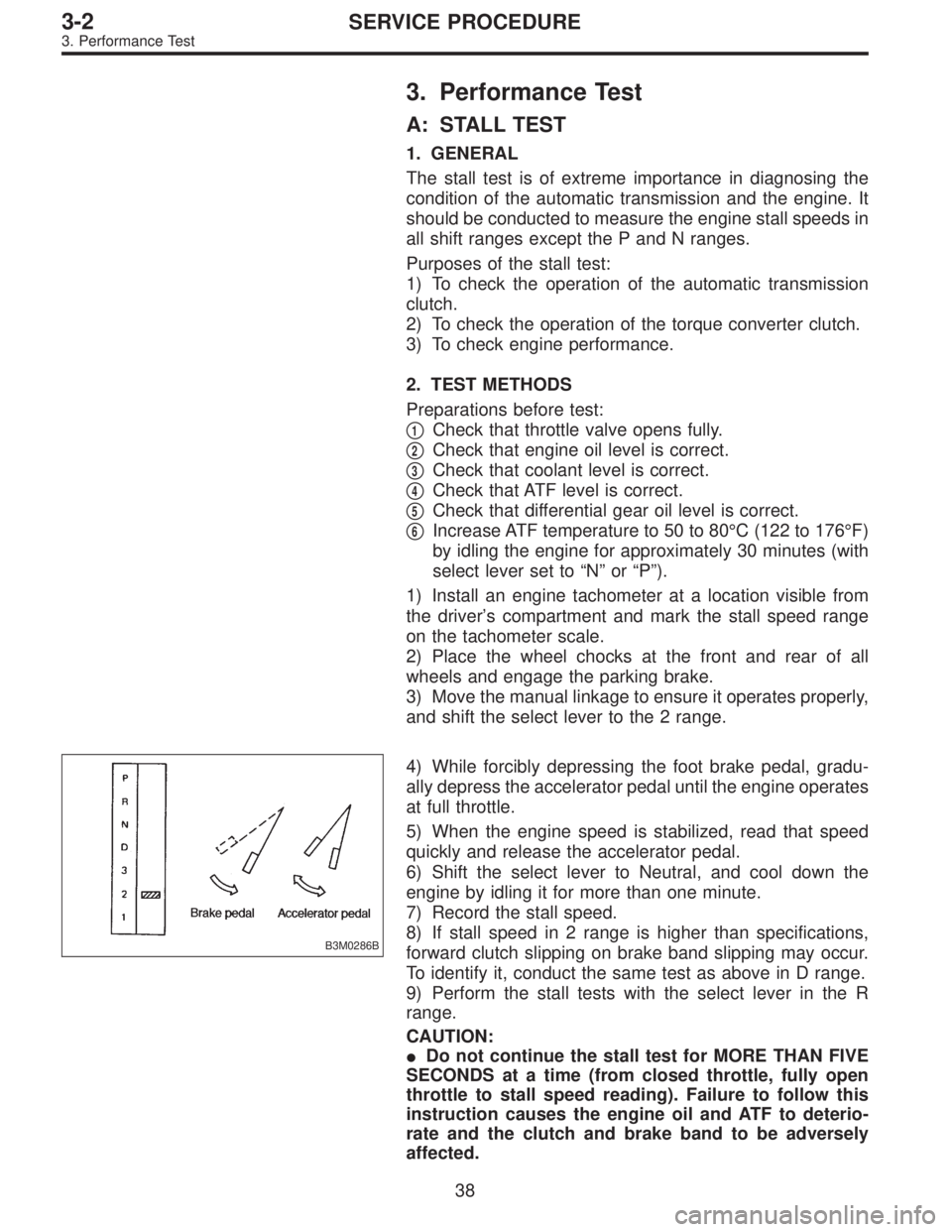
and shift the select lever to the 2 range.
B3M0286B
4) While forcibly depressing the foot brake pedal, gradu-
ally depress the accelerator pedal until the engine operates
at full throttle.
5) When the engine speed is stabilized, read that speed
quickly and release the accelerator pedal.
6) Shift the select lever to Neutral, and cool down the
engine by idling it for more than one minute.
7) Record the stall speed.
8) If stall speed in 2 range is higher than specifications,
forward clutch slipping on brake band slipping may occur.
To identify it, conduct the same test as above in D range.
9) Perform the stall tests with the select lever in the R
range.
CAUTION:
�Do not continue the stall test for MORE THAN FIVE
SECONDS at a time (from closed throttle, fully open
throttle to stall speed reading). Failure to follow this
instruction causes the engine oil and ATF to deterio-
rate and the clutch and brake band to be adversely
affected.
38
3-2SERVICE PROCEDURE
3. Performance Test
Page 854 of 3342
G3M0871
A: DISASSEMBLY
1. EXTERNAL PARTS
1) Place the transmission unit on a work bench, with the
oil pan facing down.
CAUTION:
Be careful not to bend or damage external parts.
G3M0325
2) Remove the drain plug, and drain differential oil. Tighten
the plug temporarily after draining.
G3M0326
3) Remove the drain plug, and drain automatic transmis-
sion fluid (ATF). Tighten the plug temporarily after draining.
G3M0327
4) Extract the torque converter clutch assembly.
NOTE:
�Extract the torque converter clutch horizontally. Be care-
ful not to scratch the bushing inside the oil pump shaft.
�Note that oil pump shaft also comes out.
G3M0328
5) Remove the input shaft.
48
3-2SERVICE PROCEDURE
4. Overall Transmission
Page 863 of 3342
G3M0366
30) Remove the inhibitor switch.
G3M0367
31) Remove the transmission harness.
CAUTION:
Be careful not to damage the cord insulation.
G3M0368
4. TORQUE CONVERTER CLUTCH CASE SECTION
1) Wrap the axle shaft serration with vinyl tape.
2) Remove the differential side retainer with ST.
ST 499787000 WRENCH ASSY
CAUTION:
Hold the differential case assembly by hand to avoid
damaging retainer mounting hole of the torque con-
verter clutch case and speedometer gears.
G3M0956
3) Extract the axle shaft with ST1 and ST2.
ST1 499095500 REMOVER
ST2 499247300 INSTALLER
CAUTION:
Do not reuse the circlip.
G3M0370
4) Remove the differential case assembly.
CAUTION:
�Remove the seal pipe if it is attached. (Reusing is
not allowed.)
�Be careful not to damage the retainer mounting hole
of the torque converter clutch case and the speedom-
eter gears.
57
3-2SERVICE PROCEDURE
4. Overall Transmission
Page 865 of 3342

B: ASSEMBLY OF OVERALL TRANSMISSION
1. TORQUE CONVERTER CLUTCH CASE SECTION
1) Check the appearance of each component and clean.
CAUTION:
Make sure each part is free of harmful cuts, damage
and other faults.
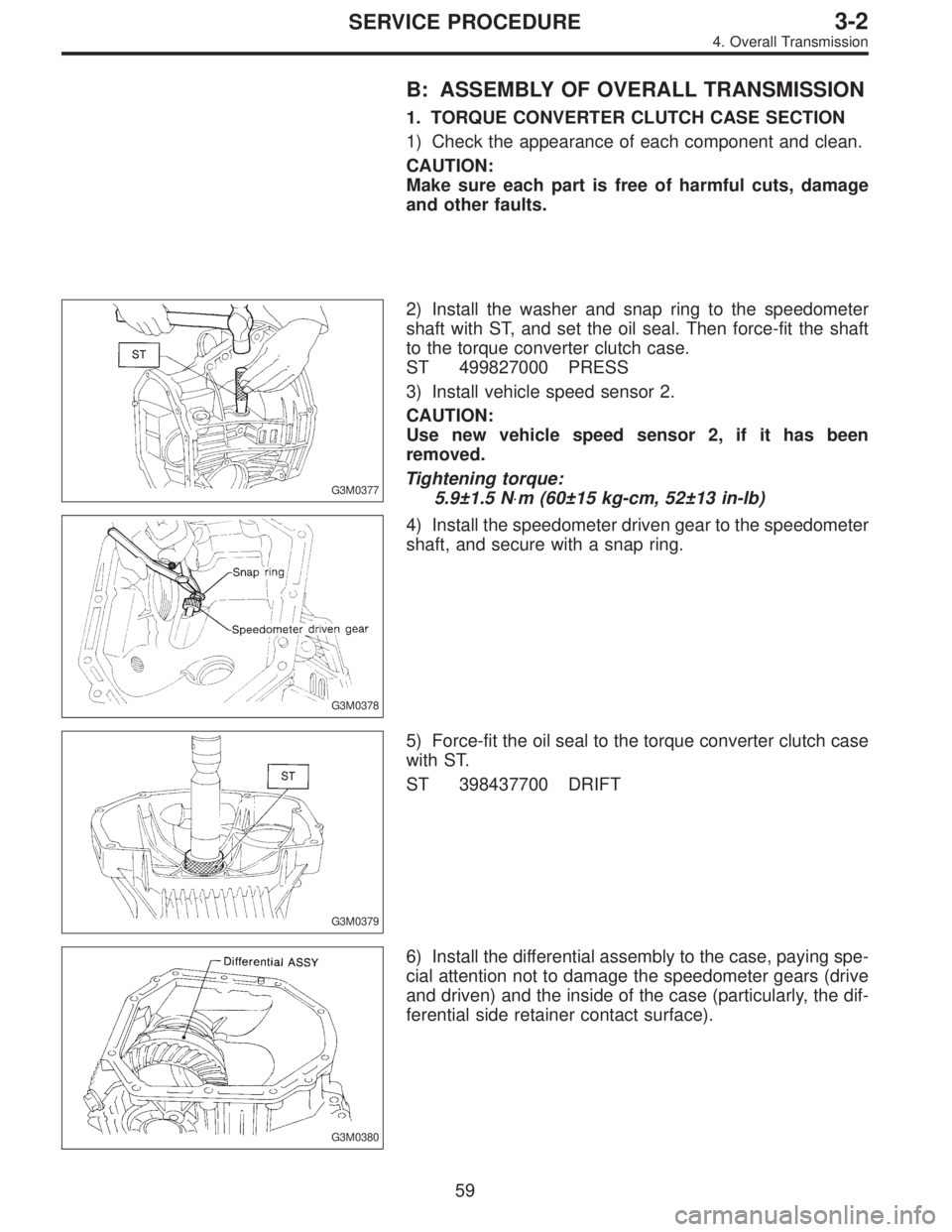
G3M0377
2) Install the washer and snap ring to the speedometer
shaft with ST, and set the oil seal. Then force-fit the shaft
to the torque converter clutch case.
ST 499827000 PRESS
3) Install vehicle speed sensor 2.
CAUTION:
Use new vehicle speed sensor 2, if it has been
removed.
Tightening torque:
5.9±1.5 N⋅m (60±15 kg-cm, 52±13 in-lb)
G3M0378
4) Install the speedometer driven gear to the speedometer
shaft, and secure with a snap ring.
G3M0379
5) Force-fit the oil seal to the torque converter clutch case
with ST.
ST 398437700 DRIFT
G3M0380
6) Install the differential assembly to the case, paying spe-
cial attention not to damage the speedometer gears (drive
and driven) and the inside of the case (particularly, the dif-
ferential side retainer contact surface).
59
3-2SERVICE PROCEDURE
4. Overall Transmission
Page 866 of 3342

7) Install the circlip to the axle shaft, insert the shaft into
the differential assembly, and tap it into position with a
plastic hammer.
Thrust play:
Approx. 0.3—0.5 mm (0.012—0.020 in)
CAUTION:
�If no play is felt, check whether the shaft is fully
inserted. If shaft insertion is correct, replace the axle
shaft.
�Be sure to use a new circlip.
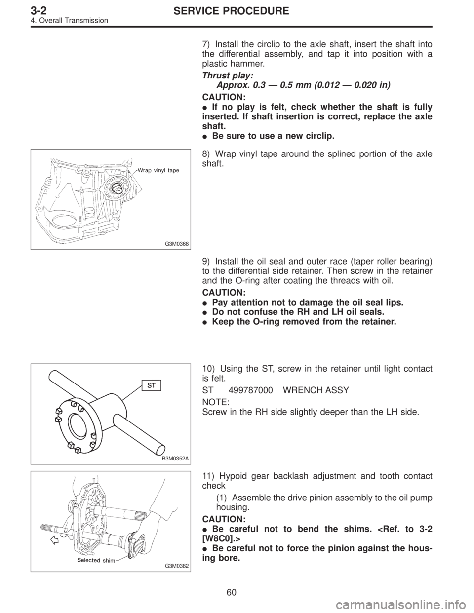
G3M0368
8) Wrap vinyl tape around the splined portion of the axle
shaft.
9) Install the oil seal and outer race (taper roller bearing)
to the differential side retainer. Then screw in the retainer
and the O-ring after coating the threads with oil.
CAUTION:
�Pay attention not to damage the oil seal lips.
�Do not confuse the RH and LH oil seals.
�Keep the O-ring removed from the retainer.
B3M0352A
10) Using the ST, screw in the retainer until light contact
is felt.
ST 499787000 WRENCH ASSY
NOTE:
Screw in the RH side slightly deeper than the LH side.
G3M0382
11) Hypoid gear backlash adjustment and tooth contact
check
(1) Assemble the drive pinion assembly to the oil pump
housing.
CAUTION:
�Be careful not to bend the shims.
[W8C0].>
�Be careful not to force the pinion against the hous-
ing bore.
60
3-2SERVICE PROCEDURE
4. Overall Transmission
Page 888 of 3342

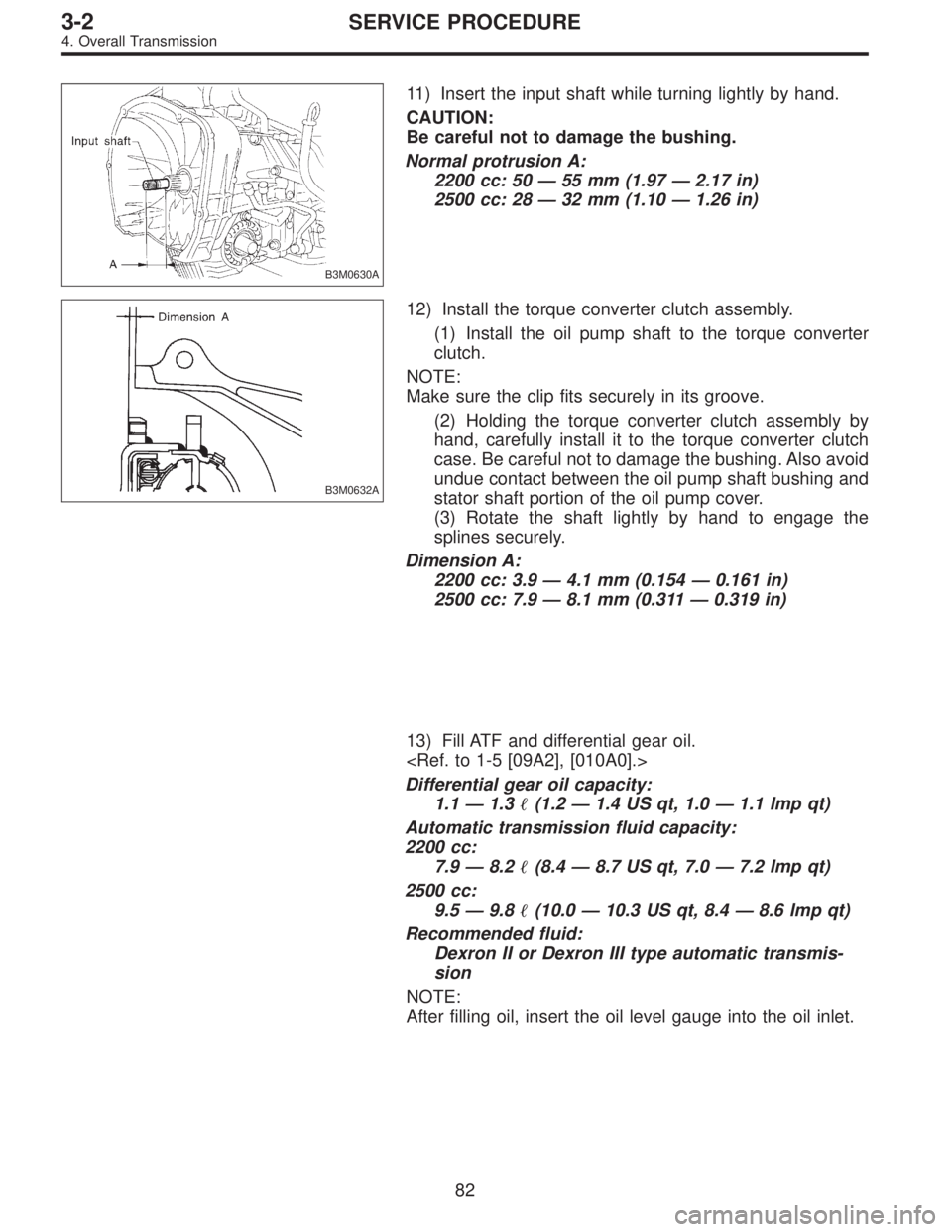
B3M0630A
11) Insert the input shaft while turning lightly by hand.
CAUTION:
Be careful not to damage the bushing.
Normal protrusion A:
2200 cc: 50—55 mm (1.97—2.17 in)
2500 cc: 28—32 mm (1.10—1.26 in)
B3M0632A
12) Install the torque converter clutch assembly.
(1) Install the oil pump shaft to the torque converter
clutch.
NOTE:
Make sure the clip fits securely in its groove.
(2) Holding the torque converter clutch assembly by
hand, carefully install it to the torque converter clutch
case. Be careful not to damage the bushing. Also avoid
undue contact between the oil pump shaft bushing and
stator shaft portion of the oil pump cover.
(3) Rotate the shaft lightly by hand to engage the
splines securely.
Dimension A:
2200 cc: 3.9—4.1 mm (0.154—0.161 in)
2500 cc: 7.9—8.1 mm (0.311—0.319 in)
13) Fill ATF and differential gear oil.
Differential gear oil capacity:
1.1—1.3�(1.2—1.4 US qt, 1.0—1.1 Imp qt)
Automatic transmission fluid capacity:
2200 cc:
7.9—8.2�(8.4—8.7 US qt, 7.0—7.2 Imp qt)
2500 cc:
9.5—9.8�(10.0—10.3 US qt, 8.4—8.6 lmp qt)
Recommended fluid:
Dexron II or Dexron III type automatic transmis-
sion
NOTE:
After filling oil, insert the oil level gauge into the oil inlet.
82
3-2SERVICE PROCEDURE
4. Overall Transmission