Page 765 of 3342
 Check the appearance of each component and clean.
CAUTION:
Make sure each part is free of harmful cuts, damage
and other")
B: ASSEMBLY OF OVERALL TRANSMISSION
1. TORQUE CONVERTER CLUTCH CASE SECTION
1) Check the appearance of each component and clean.
CAUTION:
Make sure each part is free of harmful cuts, damage
and other faults.
G3M0377
2) Install the washer and snap ring to the speedometer
shaft with ST, and set the oil seal. Then force-fit the shaft
to the torque converter clutch case.
ST 499827000 PRESS
3) Install vehicle speed sensor 2.
CAUTION:
Use new vehicle speed sensor 2, if it has been
removed.
Tightening torque:
5.9±1.5 N⋅m (60±15 kg-cm, 52±13 in-lb)
G3M0378
4) Install the speedometer driven gear to the speedometer
shaft, and secure with a snap ring.
G3M0379
5) Force-fit the oil seal to the torque converter clutch case
with ST.
ST 398437700 DRIFT
G3M0380
6) Install the differential assembly to the case, paying spe-
cial attention not to damage the speedometer gears (drive
and driven) and the inside of the case (particularly, the dif-
ferential side retainer contact surface).
59
3-2SERVICE PROCEDURE
4. Overall Transmission
Page 766 of 3342
 Install the circlip to the axle shaft, insert the shaft into
the differential assembly, and tap it into position with a
plastic hammer.
Thrust play:
Approx. 0.3—0.5 mm (0.012—0.020 in)
CAUTION:")
7) Install the circlip to the axle shaft, insert the shaft into
the differential assembly, and tap it into position with a
plastic hammer.
Thrust play:
Approx. 0.3—0.5 mm (0.012—0.020 in)
CAUTION:
�If no play is felt, check whether the shaft is fully
inserted. If shaft insertion is correct, replace the axle
shaft.
�Be sure to use a new circlip.
G3M0368
8) Wrap vinyl tape around the splined portion of the axle
shaft.
9) Install the oil seal and outer race (taper roller bearing)
to the differential side retainer. Then screw in the retainer
and the O-ring after coating the threads with oil.
CAUTION:
�Pay attention not to damage the oil seal lips.
�Do not confuse the RH and LH oil seals.
�Keep the O-ring removed from the retainer.
B3M0352A
10) Using the ST, screw in the retainer until light contact
is felt.
ST 499787000 WRENCH ASSY
NOTE:
Screw in the RH side slightly deeper than the LH side.
G3M0382
11) Hypoid gear backlash adjustment and tooth contact
check
(1) Assemble the drive pinion assembly to the oil pump
housing.
CAUTION:
�Be careful not to bend the shims.
[W8C0].>
�Be careful not to force the pinion against the hous-
ing bore.
60
3-2SERVICE PROCEDURE
4. Overall Transmission
Page 788 of 3342
 Insert the input shaft while turning lightly by hand.
CAUTION:
Be careful not to damage the bushing.
Normal protrusion A:
2200 cc: 50—55 mm (1.97—2.17 in)
2500 cc: 28—32 mm (1.10—")
B3M0630A
11) Insert the input shaft while turning lightly by hand.
CAUTION:
Be careful not to damage the bushing.
Normal protrusion A:
2200 cc: 50—55 mm (1.97—2.17 in)
2500 cc: 28—32 mm (1.10—1.26 in)
B3M0632A
12) Install the torque converter clutch assembly.
(1) Install the oil pump shaft to the torque converter
clutch.
NOTE:
Make sure the clip fits securely in its groove.
(2) Holding the torque converter clutch assembly by
hand, carefully install it to the torque converter clutch
case. Be careful not to damage the bushing. Also avoid
undue contact between the oil pump shaft bushing and
stator shaft portion of the oil pump cover.
(3) Rotate the shaft lightly by hand to engage the
splines securely.
Dimension A:
2200 cc: 3.9—4.1 mm (0.154—0.161 in)
2500 cc: 7.9—8.1 mm (0.311—0.319 in)
13) Fill ATF and differential gear oil.
Differential gear oil capacity:
1.1—1.3�(1.2—1.4 US qt, 1.0—1.1 Imp qt)
Automatic transmission fluid capacity:
2200 cc:
7.9—8.2�(8.4—8.7 US qt, 7.0—7.2 Imp qt)
2500 cc:
9.5—9.8�(10.0—10.3 US qt, 8.4—8.6 lmp qt)
Recommended fluid:
Dexron II or Dexron III type automatic transmis-
sion
NOTE:
After filling oil, insert the oil level gauge into the oil inlet.
82
3-2SERVICE PROCEDURE
4. Overall Transmission
Page 813 of 3342
G3M0488
14. Differential Case Assembly
A: DISASSEMBLY
1) Using a press and ST, remove the taper roller bearing.
ST 498077000 REMOVER
CAUTION:
Be careful not to damage the speedometer drive gear.
G3M0489
2) Secure the case in a vise and remove the crown gear
tightening bolts, then separate the crown gear, case (RH)
and case (LH).
G3M0490
3) Pull out the straight pin and shaft, and remove the dif-
ferential bevel gear, washer, and differential bevel pinion.
B: INSPECTION
Check each component for harmful cuts, damage and
other faults.
G3M0490
C: ASSEMBLY
1) Install the washer, differential bevel gear and differen-
tial bevel pinion in the differential case (RH). Insert the
pinion shaft, and fit the straight pin.
NOTE:
Install straight pin from reverse direction.
107
3-2SERVICE PROCEDURE
14. Differential Case Assembly
Page 814 of 3342
G3M0489
2) Install the washer and differential bevel gear to the dif-
ferential case (LH). Then put the case over the differential
case (RH), and connect both cases.
3) Install the crown gear and secure by tightening the bolt.
Standard tightening torque:
62±5 N⋅m (6.3±0.5 kg-m, 45.6±3.6 ft-lb)
G3M0491
4) Measurement of backlash (Selection of washer)
Measure the gear backlash with ST1 and ST2, and insert
ST2 through the access window of the case.
ST1 498247001 MAGNET BASE
ST2 498247100 DIAL GAUGE
Standard value:
0.13—0.18 mm (0.0051—0.0071 in)
NOTE:
Measure the backlash by applying a pinion tooth between
two bevel gear teeth.
G3M0492
5) Install the speedometer drive gear. Then force-fit the
taper roller bearing with a press and ST.
ST 398487700 DRIFT
CAUTION:
Be sure to position correctly the locking end of the
speedometer drive gear.
108
3-2SERVICE PROCEDURE
14. Differential Case Assembly
Page 828 of 3342
G3M0854
(7) Apply the automatic transmission fluid (ATF) onto
the parts immediately prior to assembly, and the speci-
fied tightening torque should be observed carefully.
(8) Use vaseline if it is necessary to hold parts in the
position when assembling.
(9) Drain ATF and differential gear oil into a saucer so
that the conditions of fluid and oil can be inspected.
(10) Do not support axle drive shaft, stator shaft, input
shaft or various pipes when moving transmission from
one place to another.
(11) Always discard old oil seals and O-ring, and install
new ones.
(12) Do not reuse old aluminum (overrunning clutch
pipes, etc.) pipes, gaskets, spring pins. Install new
ones.
(13) Be sure to replace parts which are damaged,
worn, scratched, discolored, etc.
22
3-2SERVICE PROCEDURE
1. Precaution
Page 830 of 3342
 Ensure the vehicle is in safe condition.
NOTE:
Do not check the oil level nor add oil to the case with the
front end of the vehicle jacked-up; this will resul")
G3M0283
2. DIFFERENTIAL GEAR OIL LEVEL
1) Ensure the vehicle is in safe condition.
NOTE:
Do not check the oil level nor add oil to the case with the
front end of the vehicle jacked-up; this will result in an
incorrect reading of the oil level.
2) Check whether the oil level is between the upper (F)
and lower (L) marks. If it is below the lower limit mark, add
oil until the level reaches the upper mark.
G3M0854
3. OIL LEAKAGE
It is difficult to accurately determine the precise position of
a oil leak, since the surrounding area also becomes wet
with oil. The places where oil seals and gaskets are used
are as follows:
Jointing portion of the case
�Transmission case and oil pump housing jointing portion
�Torque converter clutch case and oil pump housing joint-
ing portion
�Transmission case and transmission cover jointing por-
tion (FWD)
�Transmission case and extension case jointing portion
(AWD)
G3M0855
Torque converter clutch case
�Engine crankshaft oil seal
�Torque converter clutch impeller sleeve oil seal
�ATF cooler pipe connector
�Torque converter clutch
�Torque converter clutch case
�Axle shaft oil seal
�O-ring on the outside diameter of axle shaft oil seal
holder
�O-ring on the differential oil gauge
�Differential oil drain plug
�Speedometer cable mounting portion
�Location of steel balls
24
3-2SERVICE PROCEDURE
2. On-Car Service
Page 831 of 3342
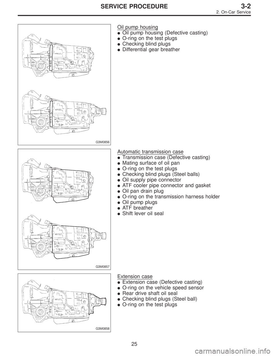
G3M0856
Oil pump housing
�Oil pump housing (Defective casting)
�O-ring on the test plugs
�Checking blind plugs
�Differential gear breather
G3M0857
Automatic transmission case
�Transmission case (Defective casting)
�Mating surface of oil pan
�O-ring on the test plugs
�Checking blind plugs (Steel balls)
�Oil supply pipe connector
�ATF cooler pipe connector and gasket
�Oil pan drain plug
�O-ring on the transmission harness holder
�Oil pump plugs
�ATF breather
�Shift lever oil seal
G3M0858
Extension case
�Extension case (Defective casting)
�O-ring on the vehicle speed sensor
�Rear drive shaft oil seal
�Checking blind plugs (Steel ball)
�O-ring on the test plugs
25
3-2SERVICE PROCEDURE
2. On-Car Service
 Using a press and ST, remove the taper roller bearing.
ST 498077000 REMOVER
CAUTION:
Be careful not to damage the speedometer drive gear.
G3M04")
 Install the washer and differential bevel gear to the dif-
ferential case (LH). Then put the case over the differential
case (RH), and connect both cases.
3) Install the crown gear and secu")
 Apply the automatic transmission fluid (ATF) onto
the parts immediately prior to assembly, and the speci-
fied tightening torque should be observed carefully.
(8) Use vaseline if it is nec")