Page 701 of 3342

B3M0337
B: ASSEMBLY
Assembly is in the reverse order of disassembly.
Do the following:
�Install thrust washer with chamfered side of inner perim-
eter facing the side gear.
�Install adjusting washer with chamfered side of inner
perimeter facing the viscous coupling using ST.
ST 499547300 INSTALLER SET
B3M0095A
1) Selection of snap ring (Inner-110)
(1) After assembling, using a thickness gauge mea-
sure clearance between snap ring�
1and center differ-
ential case.
Clearance:
0—0.15 mm (0—0.0059 in)
(2) If the measurement is not within the specification,
select suitable snap ring.
Snap ring (Inner-110)
Part No. Thickness mm (in)
805100061 2.10 (0.0827)
805100062 2.21 (0.0870)
805100063 2.32 (0.0913)
B3M0096A
2) Selection of adjusting washer (Backlash adjustment)
(1) After assembling, set up a ST1 and ST2 to end of
viscous coupling shaft. Move viscous coupling up and
down, and measure backlash in the axial direction.
ST1 498247001 MAGNET BASE
ST2 498247100 DIAL GAUGE
Backlash:
0.62—0.86 mm (0.0244—0.0339 in)
(2) If the measurement is not within the specification,
select suitable washer.
Adjusting washer (45 x 62 x t)
Part No. Thickness mm (in)
803045041 1.60 (0.0630)
803045042 1.80 (0.0709)
803045043 2.00 (0.0787)
803045044 2.20 (0.0866)
803045045 2.40 (0.0945)
67
3-1SERVICE PROCEDURE
8. Center Differential (AWD Model)
Page 702 of 3342
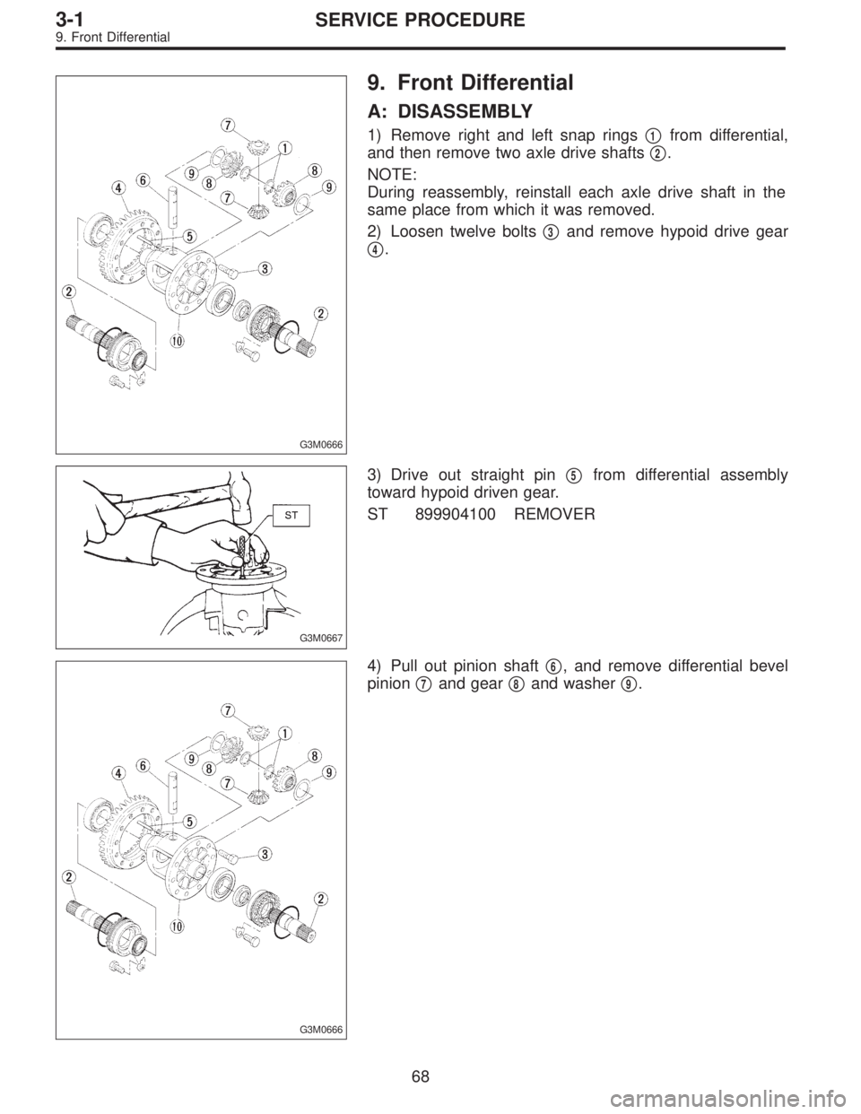
G3M0666
9. Front Differential
A: DISASSEMBLY
1) Remove right and left snap rings�1from differential,
and then remove two axle drive shafts�
2.
NOTE:
During reassembly, reinstall each axle drive shaft in the
same place from which it was removed.
2) Loosen twelve bolts�
3and remove hypoid drive gear
�
4.
G3M0667
3) Drive out straight pin�5from differential assembly
toward hypoid driven gear.
ST 899904100 REMOVER
G3M0666
4) Pull out pinion shaft�6, and remove differential bevel
pinion�
7and gear�8and washer�9.
68
3-1SERVICE PROCEDURE
9. Front Differential
Page 703 of 3342
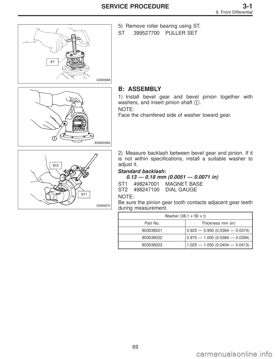
G3M0668
5) Remove roller bearing using ST.
ST 399527700 PULLER SET
B3M0099A
B: ASSEMBLY
1) Install bevel gear and bevel pinion together with
washers, and insert pinion shaft�
1.
NOTE:
Face the chamfered side of washer toward gear.
G3M0670
2) Measure backlash between bevel gear and pinion. If it
is not within specifications, install a suitable washer to
adjust it.
Standard backlash:
0.13—0.18 mm (0.0051—0.0071 in)
ST1 498247001 MAGNET BASE
ST2 498247100 DIAL GAUGE
NOTE:
Be sure the pinion gear tooth contacts adjacent gear teeth
during measurement.
Washer (38.1 x 50 x t)
Part No. Thickness mm (in)
803038021 0.925—0.950 (0.0364—0.0374)
803038022 0.975—1.000 (0.0384—0.0394)
803038023 1.025—1.050 (0.0404—0.0413)
69
3-1SERVICE PROCEDURE
9. Front Differential
Page 704 of 3342
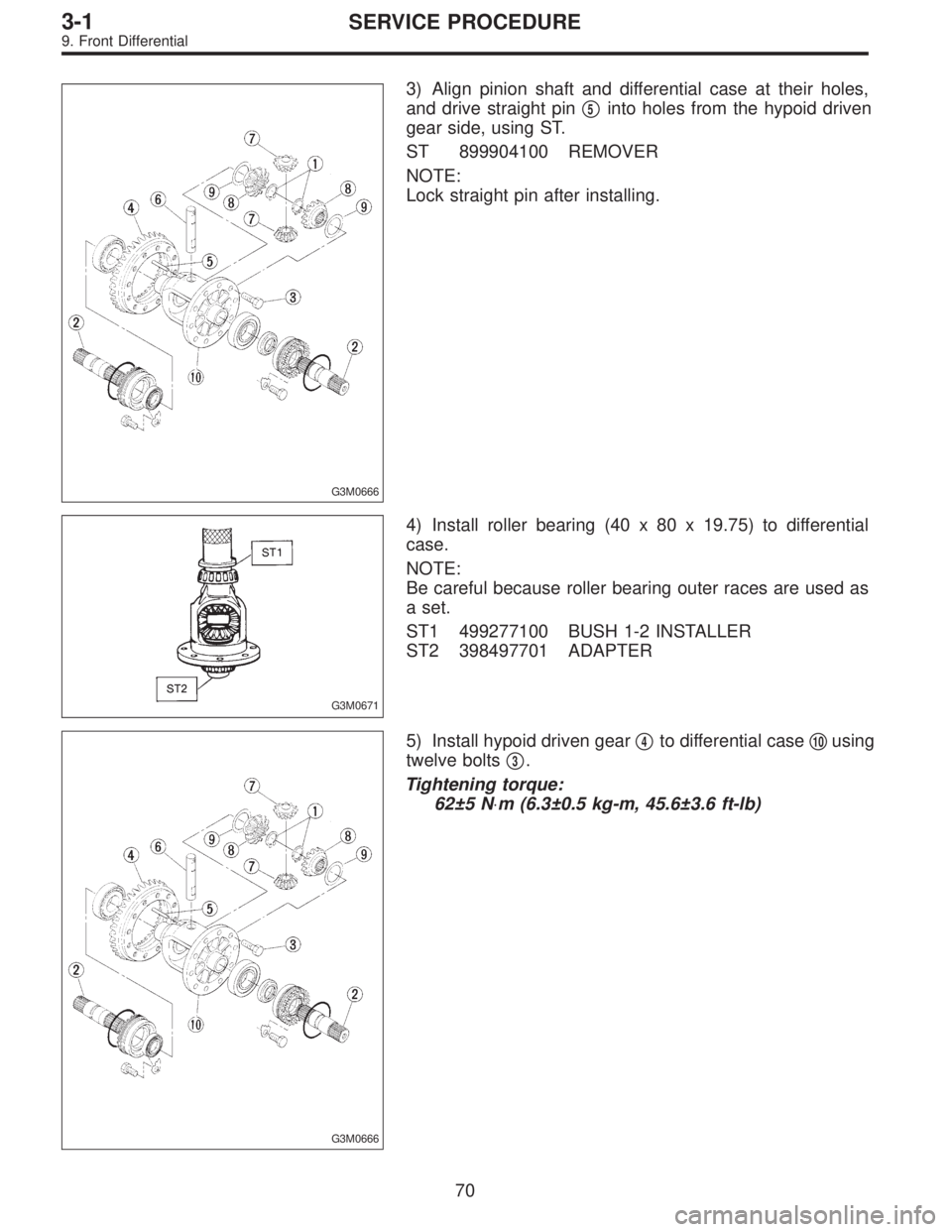
G3M0666
3) Align pinion shaft and differential case at their holes,
and drive straight pin�
5into holes from the hypoid driven
gear side, using ST.
ST 899904100 REMOVER
NOTE:
Lock straight pin after installing.
G3M0671
4) Install roller bearing (40 x 80 x 19.75) to differential
case.
NOTE:
Be careful because roller bearing outer races are used as
a set.
ST1 499277100 BUSH 1-2 INSTALLER
ST2 398497701 ADAPTER
G3M0666
5) Install hypoid driven gear�4to differential case�10using
twelve bolts�
3.
Tightening torque:
62±5 N⋅m (6.3±0.5 kg-m, 45.6±3.6 ft-lb)
70
3-1SERVICE PROCEDURE
9. Front Differential
Page 705 of 3342
B3M0100
6) Position drive axle shaft in differential case and hold it
with outer snap ring (28). Using a thickness gauge, mea-
sure clearance between the shaft and case is within speci-
fications.
Clearance:
0—0.2 mm (0—0.008 in)
If it is not within specifications, replace snap ring with a
suitable one.
Snap ring (Outer-28)
Part No. Thickness mm (in)
805028011 1.05 (0.0413)
805028012 1.20 (0.0472)
71
3-1SERVICE PROCEDURE
9. Front Differential
Page 706 of 3342

1. Manual Transmission and
Differential
Symptom and possible cause Remedy
1. Gears are difficult to intermesh.
The cause for difficulty in shifting gears can be classified into two kinds: one is malfunction of the gear shift system and the
other is malfunction of the transmission. However, if the operation is heavy and engagement of the gears is difficult, defective
clutch disengagement may also be responsible. Check whether the clutch is correctly functioning, before checking the gear
shift system and transmission.
(a) Worn, damaged or burred chamfer of internal spline of
sleeve and reverse driven gearReplace.
(b) Worn, damaged or burred chamfer of spline of gears Replace.
(c) Worn or scratched bushings Replace.
(d) Incorrect contact between synchronizer ring and gear
cone or wearCorrect or replace.
2. Gear slips out.
(1) Gear slips out when coasting on rough road.
(2) Gear slips out during acceleration.
(a) Defective pitching stopper adjustment Adjust.
(b) Loose engine mounting bolts Tighten or replace.
(c) Worn fork shifter, broken shifter fork rail spring Replace.
(d) Worn or damaged ball bearing Replace.
(e) Excessive clearance between splines of synchronizer hub
and synchronizer sleeveReplace.
(f) Worn tooth step of synchronizer hub (responsible for slip-
out of 3rd gear)Replace.
(g) Worn 1st driven gear, needle bearing and race Replace.
(h) Worn 2nd driven gear, needle bearing and race Replace.
(i) Worn 3rd drive gear and bushing Replace.
(j) Worn 4th drive gear and bushing Replace.
(k) Worn reverse idler gear and bushing Replace.
3. Unusual noise comes from transmission.
If an unusual noise is heard when the vehicle is parked with its engine idling and if the noise ceases when the clutch is
disengaged, it may be considered that the noise comes from the transmission.
(a) Insufficient or improper lubrication Lubricate or replace with specified oil.
(b) Worn or damaged gears and bearings Replace.
NOTE: If the trouble is only wear of the tooth surfaces, merely
a high roaring noise will occur at high speeds, but if any part
is broken, rhythmical knocking sound will be heard even at
low speeds.
72
3-1DIAGNOSTICS
1. Manual Transmission and Differential
Page 707 of 3342

Abnormal noise will develop and finally it will become impossible to continue to run due to broken pieces obstructi")
Symptom and possible cause Remedy
4. Broken differential (case, gear, bearing, etc.)
Abnormal noise will develop and finally it will become impossible to continue to run due to broken pieces obstructing the gear
revolution.
(a) Insufficient or improper oil Disassemble differential and replace broken components and
at the same time check other components for any trouble,
and replace if necessary.
(b) Use of vehicle under severe conditions such as excessive
load and improper use of clutchReadjust bearing preload and backlash and face contact of
gears.
(c) Improper adjustment of taper roller bearing Adjust.
(d) Improper adjustment of drive pinion and hypoid driven
gearAdjust.
(e) Excessive backlash due to worn differential side gear,
washer or differential pinionAdd recommended oil to specified level. Do not use vehicle
under severe operating conditions.
(f) Loose hypoid driven gear clamping bolts Tighten.
5. Differential and hypoid gear noises
Troubles of the differential and hypoid gear always appear as noise problems. Therefore noise is the first indication of the
trouble. However noises from the engine, muffler, tire, exhaust gas, bearing, body, etc. are easily mistaken for the differential
noise. Pay special attention to the hypoid gear noise because it is easily confused with other gear noises. There are the
following four kinds of noises.
(1) Gear noise when driving: If noise increases as vehicle speed increases it may be due to insufficient gear oil, incorrect
gear engagement, damaged gears, etc.
(2) Gear noise when coasting: Damaged gears due to maladjusted bearings and incorrect shim adjustment
(3) Bearing noise when driving or when coasting: Cracked, broken or damaged bearings
(4) Noise which mainly occurs when turning: Unusual noise from differential side gear, differential pinion, differential pinion
shaft, etc.
(a) Insufficient oil Lubricate.
(b) Improper adjustment of hypoid driven gear and drive
pinionCheck tooth contact.
(c) Worn teeth of hypoid driven gear and drive pinion Replace as a set.
Readjust bearing preload.
(d) Loose roller bearing Readjust hypoid driven gear to drive pinion backlash and
check tooth contact.
(e) Distorted hypoid driven gear or differential case Replace.
(f) Worn washer and differential pinion shaft Replace.
73
3-1DIAGNOSTICS
1. Manual Transmission and Differential
Page 708 of 3342

1. Automatic Transmission and
Differential
A: SPECIFICATIONS
Torque
converter
clutchType Symmetric, 3 element, single stage, 2 phase torque converter clutch coupling
Stall torque ratio2200 cc 2.1 — 2.3
2500 cc 1.8 — 2.0
OUTBACK 2.2 — 2.4
Nominal diameter2200 cc 236 mm (9.29 in)
2500 cc 246 mm (9.69 in)
Stall speed (at sea level)2200 cc 2,200 — 2,600 rpm
2500 cc 2,200 — 2,600 rpm
OUTBACK 2,300 — 2,700 rpm
One-way clutch Sprague type one-way clutch
Automatic
transmissionTransmissionType 4-forward, 1-reverse, double-row planetary gears
Control elementMulti-plate clutch 4 sets
Multi-plate brake 1 set
Band brake 1 set
One-way clutch (sprague type) 2 sets
Gear ratio1st2200 cc 2.785
2500 cc 3.027
2nd2200 cc 1.545
2500 cc 1.619
3rd 1.000
4th 0.694
Reverse 2.272
Tooth number of
planetary gearFront sun gear 33
Front pinion 21
Front internal gear 75
Rear sun gear2200 cc 42
2500 cc 37
Rear pinion2200 cc 17
2500 cc 19
Rear internal gear 75
Clutch number of reverse
clutchDrive plate & driven plate 2
Clutch number of
high clutchDrive plate & driven plate2200 cc ... 4
2500 cc ... 5
Clutch number of forward
clutchDrive plate & driven plate 5
Clutch number of
overrunning clutchDrive plate & driven plate 3
Clutch number of low &
reverse brakeDrive plate & driven plateExcept OUTBACK ... 5
OUTBACK ... 6
Selector positionP (Park)Transmission in neutral, output member
immovable, and engine start possible
R (Reverse) Transmission in reverse for backing
N (Neutral) Transmission in neutral, and engine start possible
D (Drive) Automatic gear change 1st
+
,2nd+
,3rd+
,4th
3 (3rd) Automatic gear change 1st+
,2nd+
,3rd+4th
2 (2nd)2nd gear locked
(Deceleration possible 4th,3rd,2nd)
1 (1st)1st gear locked
(Deceleration possible 4th,3rd,2nd,1st)
Control method Hydraulic remote control
2
3-2SPECIFICATIONS AND SERVICE DATA
1. Automatic Transmission and Differential
 Position drive axle shaft in differential case and hold it
with outer snap ring (28). Using a thickness gauge, mea-
sure clearance between the shaft and case is within speci-
fications.
Cle")