Page 636 of 3342

5. SHIFTER FORK AND ROD
Select suitable shifter forks so that both coupling sleeve and
reverse driven gear are positioned in the center of their synchro-
mesh mechanisms.
1st-2nd shifter fork
Part No. Mark Remarks
32804AA060 1Approach to 1st gear by
0.2 mm (0.008 in)
32804AA070 No mark Standard
32804AA080 3Approach to 2nd gear by
0.2 mm (0.008 in)
3rd-4th shifter fork
Part No. Mark Remarks
32810AA060 1Approach to 4th gear by
0.2 mm (0.008 in)
32810AA070 No mark Standard
32810AA100 3Approach to 3rd gear by
0.2 mm (0.008 in)
5th shifter fork
Part No. Mark Remarks
32812AA200 4Approach to 5th gear by
0.2 mm (0.008 in)
32812AA210 No mark Standard
32812AA220 6Become distant from 5th
gear by 0.2 mm (0.008 in)
Rod end clearance
A: 1st-2nd—3rd-4th
0.5—1.5 mm (0.020—0.059 in)
B: 3rd-4th—5th
0.6—1.4 mm (0.024—0.055 in)
6. TRANSMISSION CASE ASSEMBLY
Drive pinion shim adjustment
Drive pinion shim
Part No.Thickness
mm (in)Part No.Thickness
mm (in)
32295AA0310.150
(0.0059)32295AA0710.250
(0.0098)
32295AA0410.175
(0.0069)32295AA0810.275
(0.0108)
32295AA0510.200
(0.0079)32295AA0910.300
(0.0118)
32295AA0610.225
(0.0089)32295AA1010.500
(0.0197)
Hypoid gear backlash
0.13—0.18 mm (0.0051—0.0071 in)Selection of main shaft rear plate
Main shaft rear plate
Dimension“A”mm (in) Part No. Mark
4.00—4.13 (0.1575—0.1626) 32294AA041 1
3.87—3.99 (0.1524—0.1571) 32294AA051 2
7. DRIVE PINION ASSEMBLY
Preload adjustment of thrust bearing
Starting torque
0.3—0.8 N⋅m(3—8 kg-cm, 2.6—6.9 in-lb)
Adjusting washer No. 1
Part No. Thickness mm (in)
803025051 3.925 (0.1545)
803025052 3.950 (0.1555)
803025053 3.975 (0.1565)
803025054 4.000 (0.1575)
803025055 4.025 (0.1585)
803025056 4.050 (0.1594)
803025057 4.075 (0.1604)
Adjusting washer No. 2
Part No. Thickness mm (in)
803025059 3.850 (0.1516)
803025054 4.000 (0.1575)
803025058 4.150 (0.1634)
Assemble a driven shaft and 1st driven gear that are selected for
the proper radial clearance adjustment.
Driven shaft 1st driven gear
Part No.Diameter A
mm (in)Part No.
32229AA15049.959—49.966
(1.9669—
1.9672)32231AA290
32229AA14049.967—49.975
(1.9672—
1.9675)32231AA280
8. DRIVE PINION ASSEMBLY (FWD Model)
Selection of 1st driven gear:
1st driven gear
Outer diameter of bushing mm (in) Part No.
41.983—41.996 (1.6529—1.6534) 32231AA320
41.968—41.982 (1.6523—1.6528) 32231AA330
41.954—41.967 (1.6517—1.6522) 32231AA340
4
3-1SPECIFICATIONS AND SERVICE DATA
1. Manual Transmission and Differential
Page 637 of 3342

Snap ring (Inner-110) to center differential case clearance
0—0.15 mm (0—0.0059 in)
Snap ring (Inner-110)
Part No. Thickness mm (in)
805100061 2.10 (0.0827)
8051")
9. CENTER DIFFERENTIAL (AWD Model)
Snap ring (Inner-110) to center differential case clearance
0—0.15 mm (0—0.0059 in)
Snap ring (Inner-110)
Part No. Thickness mm (in)
805100061 2.10 (0.0827)
805100062 2.21 (0.0870)
805100063 2.32 (0.0913)
Backlash adjustment axial movement
0.62—0.86 mm (0.0244—0.0339 in)
Adjusting washer (45 x 62 x t)
Part No. Thickness mm (in)
803045041 1.60 (0.0630)
803045042 1.80 (0.0709)
803045043 2.00 (0.0787)
803045044 2.20 (0.0866)
803045045 2.40 (0.0945)
10. FRONT DIFFERENTIAL
Bevel gear to pinion backlash
0.13—0.18 mm (0.0051—0.0071 in)
Washer (38.1 x 50 x t)
Part No.Thickness
mm (in)Part No.Thickness
mm (in)
8030380210.925—
0.950
(0.0364—
0.0374)8030380231.025—
1.050
(0.0404—
0.0413)
8030380220.975—
1.000
(0.0384—
0.0394)
Pinion shaft to axle drive shaft clearance
0—0.2 mm (0—0.008 in)
Snap ring (Outer-28)
Part No.Thickness
mm (in)Part No.Thickness
mm (in)
805028011 1.05 (0.0413) 805028012 1.20 (0.0472)
5
3-1SPECIFICATIONS AND SERVICE DATA
1. Manual Transmission and Differential
Page 642 of 3342
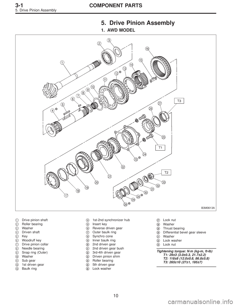
5. Drive Pinion Assembly
1. AWD MODEL
B3M0613A
�1Drive pinion shaft
�
2Roller bearing
�
3Washer
�
4Driven shaft
�
5Key
�
6Woodruff key
�
7Drive pinion collar
�
8Needle bearing
�
9Snap ring (Outer)
�
10Washer
�
11Sub gear
�
121st driven gear
�
13Baulk ring�
141st-2nd synchronizer hub
�
15Insert key
�
16Reverse driven gear
�
17Outer baulk ring
�
18Synchro cone
�
19Inner baulk ring
�
202nd driven gear
�
212nd driven gear bush
�
223rd-4th driven gear
�
23Driven pinion shim
�
24Roller bearing
�
255th driven gear
�
26Lock washer�
27Lock nut
�
28Washer
�
29Thrust bearing
�
30Differential bevel gear sleeve
�
31Washer
�
32Lock washer
�
33Lock nut
Tightening torque: N⋅m (kg-m, ft-lb)
T1: 29±3 (3.0±0.3, 21.7±2.2)
T2: 118±8 (12.0±0.8, 86.8±5.8)
T3: 265±10 (27±1, 195±7)
10
3-1COMPONENT PARTS
5. Drive Pinion Assembly
Page 645 of 3342
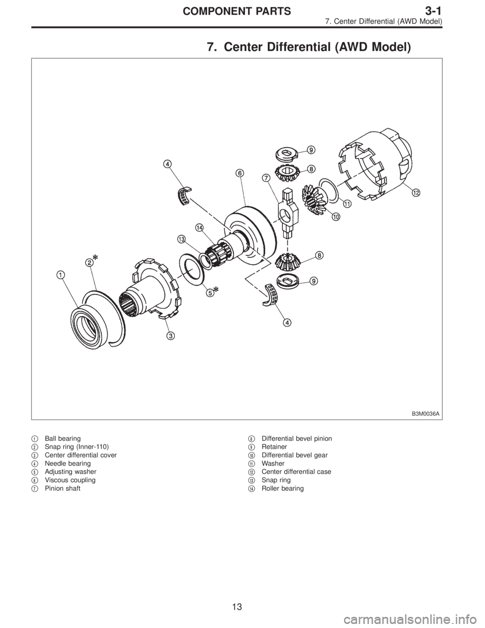
7. Center Differential (AWD Model)
B3M0036A
�1Ball bearing
�
2Snap ring (Inner-110)
�
3Center differential cover
�
4Needle bearing
�
5Adjusting washer
�
6Viscous coupling
�
7Pinion shaft�
8Differential bevel pinion
�
9Retainer
�
10Differential bevel gear
�
11Washer
�
12Center differential case
�
13Snap ring
�
14Roller bearing
13
3-1COMPONENT PARTS
7. Center Differential (AWD Model)
Page 646 of 3342
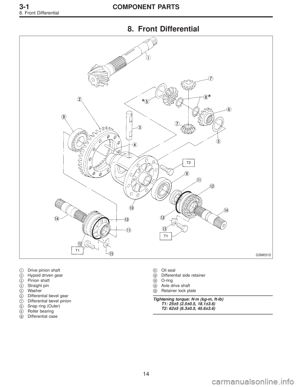
8. Front Differential
G3M0515
�1Drive pinion shaft
�
2Hypoid driven gear
�
3Pinion shaft
�
4Straight pin
�
5Washer
�
6Differential bevel gear
�
7Differential bevel pinion
�
8Snap ring (Outer)
�
9Roller bearing
�
10Differential case�
11Oil seal
�
12Differential side retainer
�
13O-ring
�
14Axle drive shaft
�
15Retainer lock plate
Tightening torque: N⋅m (kg-m, ft-lb)
T1: 25±5 (2.5±0.5, 18.1±3.6)
T2: 62±5 (6.3±0.5, 45.6±3.6)
14
3-1COMPONENT PARTS
8. Front Differential
Page 647 of 3342
1. General
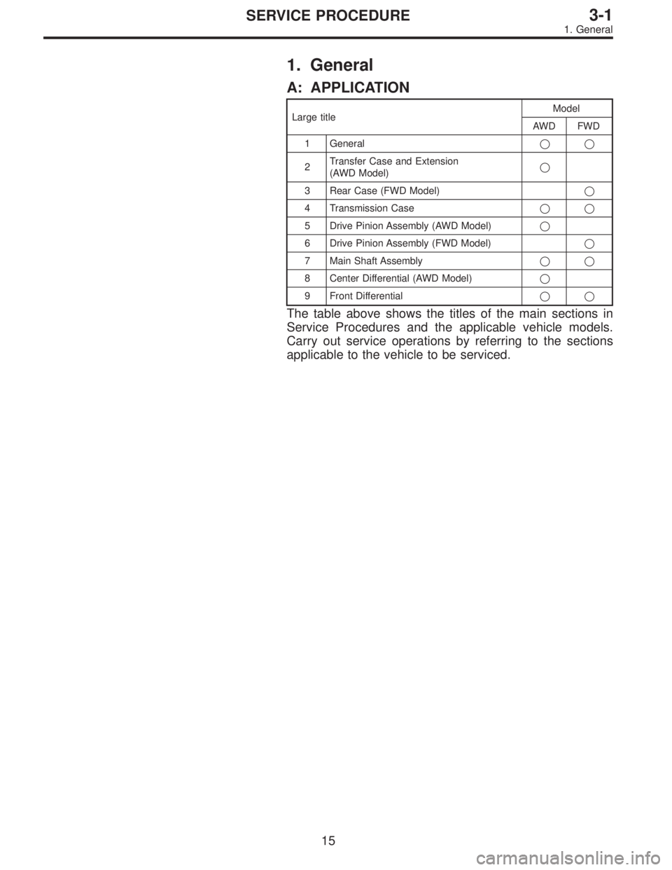
A: APPLICATION
Large titleModel
AWD FWD
1 General��
2Transfer Case and Extension
(AWD Model)�
3 Rear Case (FWD Model)�
4 Transmission Case��
5 Drive Pinion Assembly (AWD Model)�
6 Drive Pinion Assembly (FWD Model)�
7 Main Shaft Assembly��
8 Center Differential (AWD Model)�
9 Front Differential��
The table above shows the titles of the main sections in
Service Procedures and the applicable vehicle models.
Carry out service operations by referring to the sections
applicable to the vehicle to be serviced.
15
3-1SERVICE PROCEDURE
1. General
Page 650 of 3342
6) Oil seal
Replace the oil seal if the lip is deformed, hardened,
damaged, worn, or defective in any way.
7) O-ring
Replace the O-ring if the sealing face is deformed,
hardened, damaged, worn, or defective in any way.
8) Gearshift mechanism
Repair or replace the gearshift mechanism if excessively
worn, bent, or defective in any way.
G3M0521
9) Differential gear
Repair or replace the differential gear in the following
cases:
(1) The hypoid drive gear and drive pinion shaft tooth
surface are damaged, excessively worn, or seized.
(2) The roller bearing on the drive pinion shaft has a
worn or damaged roller path.
(3) There is damage, wear, or seizure of the differen-
tial bevel pinion, differential bevel gear, washer, pinion
shaft, and straight pin.
(4) The differential case has worn or damaged sliding
surfaces.
18
3-1SERVICE PROCEDURE
1. General
Page 652 of 3342
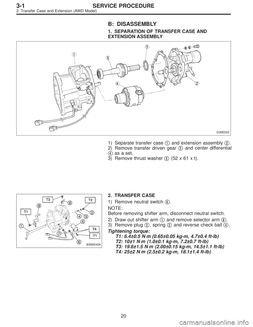
B: DISASSEMBLY
1. SEPARATION OF TRANSFER CASE AND
EXTENSION ASSEMBLY
G3M0523
1) Separate transfer case�1and extension assembly�2.
2) Remove transfer driven gear�
3and center differential
�
4as a set.
3) Remove thrust washer�
5(52x61xt).
B3M0042A
2. TRANSFER CASE
1) Remove neutral switch�
6.
NOTE:
Before removing shifter arm, disconnect neutral switch.
2) Draw out shifter arm�
1and remove selector arm�8.
3) Remove plug�
2, spring�3and reverse check ball�4.
Tightening torque:
T1: 6.4±0.5 N⋅m (0.65±0.05 kg-m, 4.7±0.4 ft-lb)
T2: 10±1 N⋅m (1.0±0.1 kg-m, 7.2±0.7 ft-lb)
T3: 19.6±1.5 N⋅m (2.00±0.15 kg-m, 14.5±1.1 ft-lb)
T4: 25±2 N⋅m (2.5±0.2 kg-m, 18.1±1.4 ft-lb)
20
3-1SERVICE PROCEDURE
2. Transfer Case and Extension (AWD Model)
 Oil seal
Replace the oil seal if the lip is deformed, hardened,
damaged, worn, or defective in any way.
7) O-ring
Replace the O-ring if the sealing face is deformed,
hardened, damaged, worn, or def")