Page 1041 of 3342
H3M1180A
B: IDENTIFICATION
When replacing a rear differential assembly, select the cor-
rect one according to the following table.
CAUTION:
Using the different rear differential assembly causes
the drive line and tires to “drag” or emit abnormal
noise when AWD is selected.
Gear ratio Part number Stamp on rear differential
2200 cc
MT3.900 27011AA330
B3M0124
2200 cc
AT
4.111 27011AA340
B3M0127
2500 cc
MT
2500 cc
AT4.444 27011AA410
B3M0421
3
3-4SPECIFICATIONS AND SERVICE DATA
1. AWD System
Page 1044 of 3342
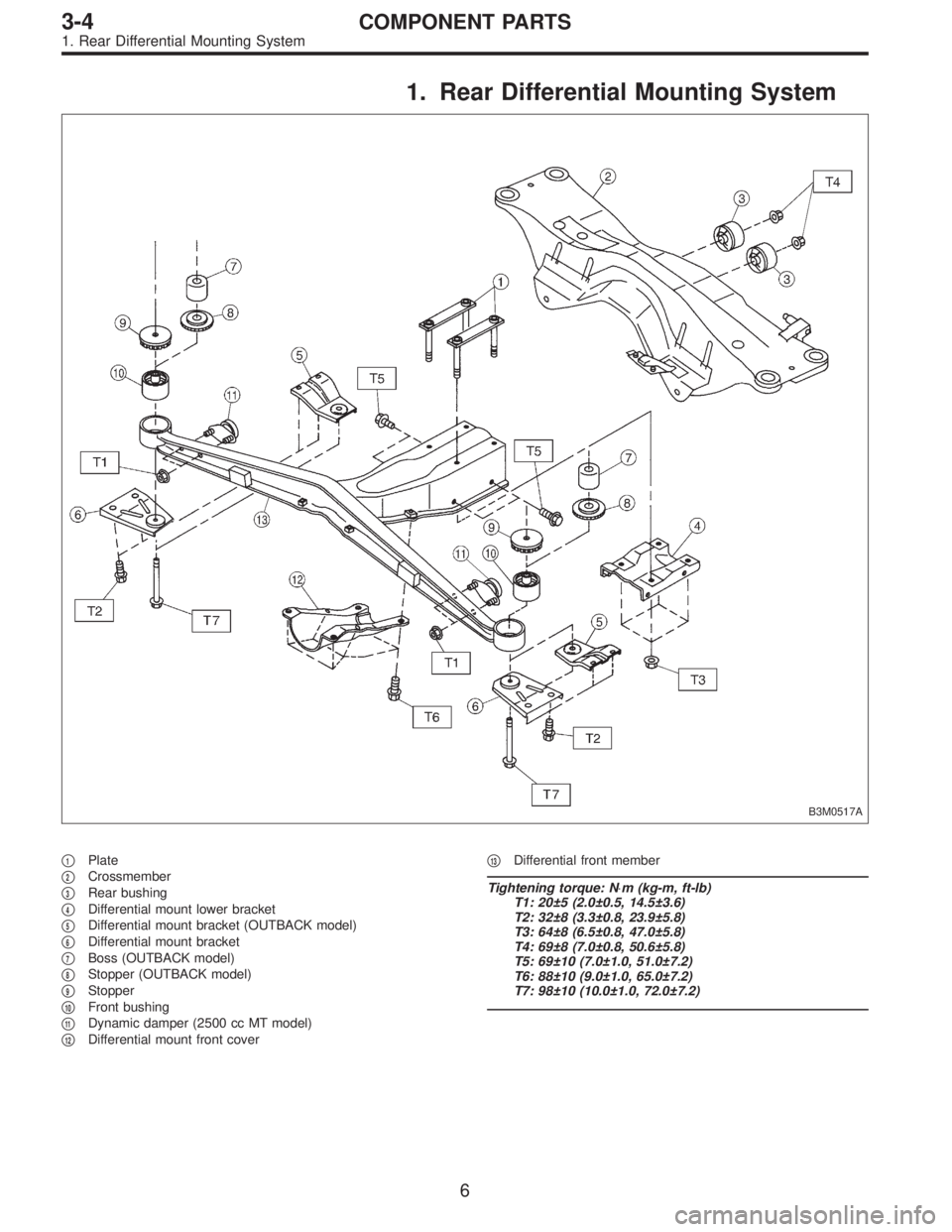
1. Rear Differential Mounting System
B3M0517A
�1Plate
�
2Crossmember
�
3Rear bushing
�
4Differential mount lower bracket
�
5Differential mount bracket (OUTBACK model)
�
6Differential mount bracket
�
7Boss (OUTBACK model)
�
8Stopper (OUTBACK model)
�
9Stopper
�
10Front bushing
�
11Dynamic damper (2500 cc MT model)
�
12Differential mount front cover�
13Differential front member
Tightening torque: N⋅m (kg-m, ft-lb)
T1: 20±5 (2.0±0.5, 14.5±3.6)
T2: 32±8 (3.3±0.8, 23.9±5.8)
T3: 64±8 (6.5±0.8, 47.0±5.8)
T4: 69±8 (7.0±0.8, 50.6±5.8)
T5: 69±10 (7.0±1.0, 51.0±7.2)
T6: 88±10 (9.0±1.0, 65.0±7.2)
T7: 98±10 (10.0±1.0, 72.0±7.2)
6
3-4COMPONENT PARTS
1. Rear Differential Mounting System
Page 1045 of 3342
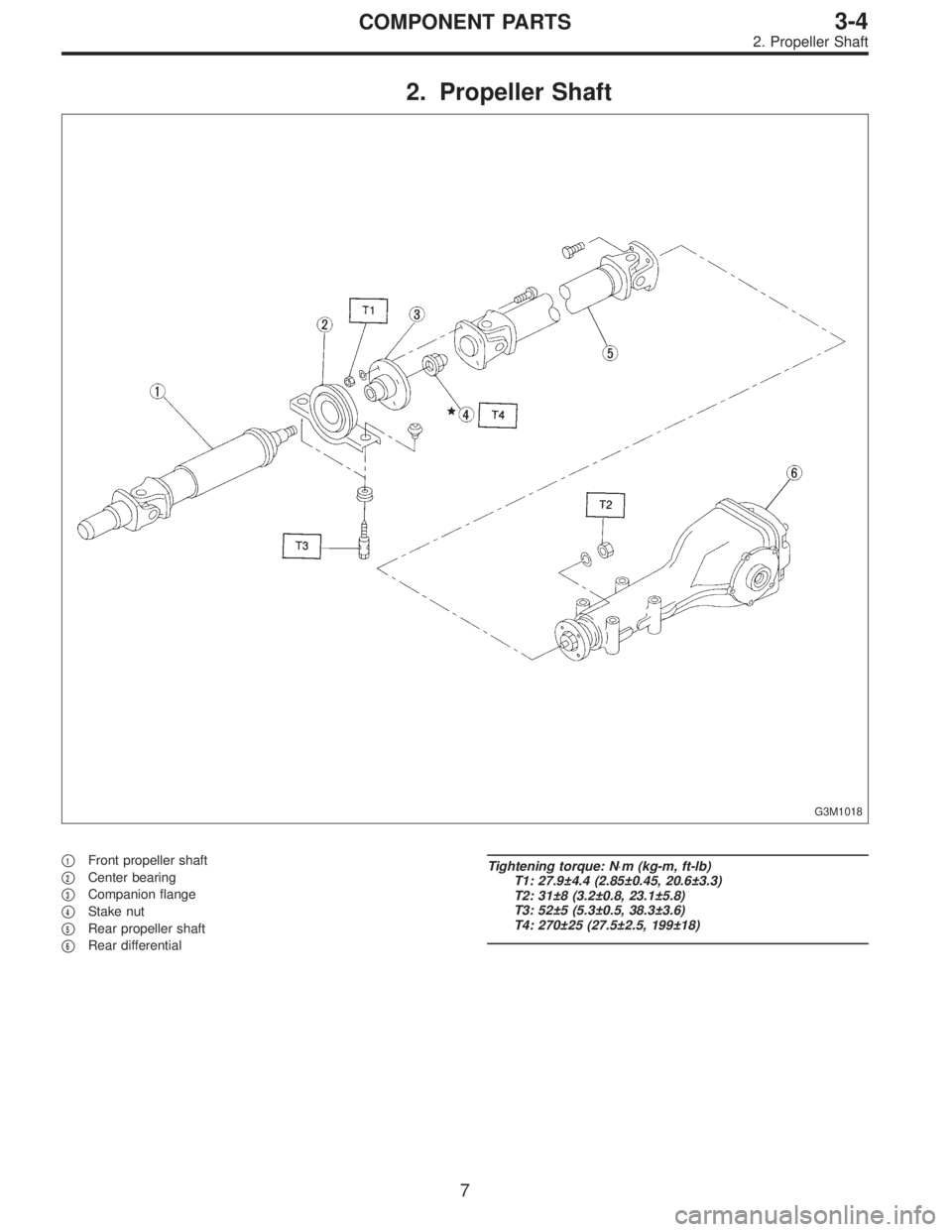
2. Propeller Shaft
G3M1018
�1Front propeller shaft
�
2Center bearing
�
3Companion flange
�
4Stake nut
�
5Rear propeller shaft
�
6Rear differential
Tightening torque: N⋅m (kg-m, ft-lb)
T1: 27.9±4.4 (2.85±0.45, 20.6±3.3)
T2: 31±8 (3.2±0.8, 23.1±5.8)
T3: 52±5 (5.3±0.5, 38.3±3.6)
T4: 270±25 (27.5±2.5, 199±18)
7
3-4COMPONENT PARTS
2. Propeller Shaft
Page 1046 of 3342
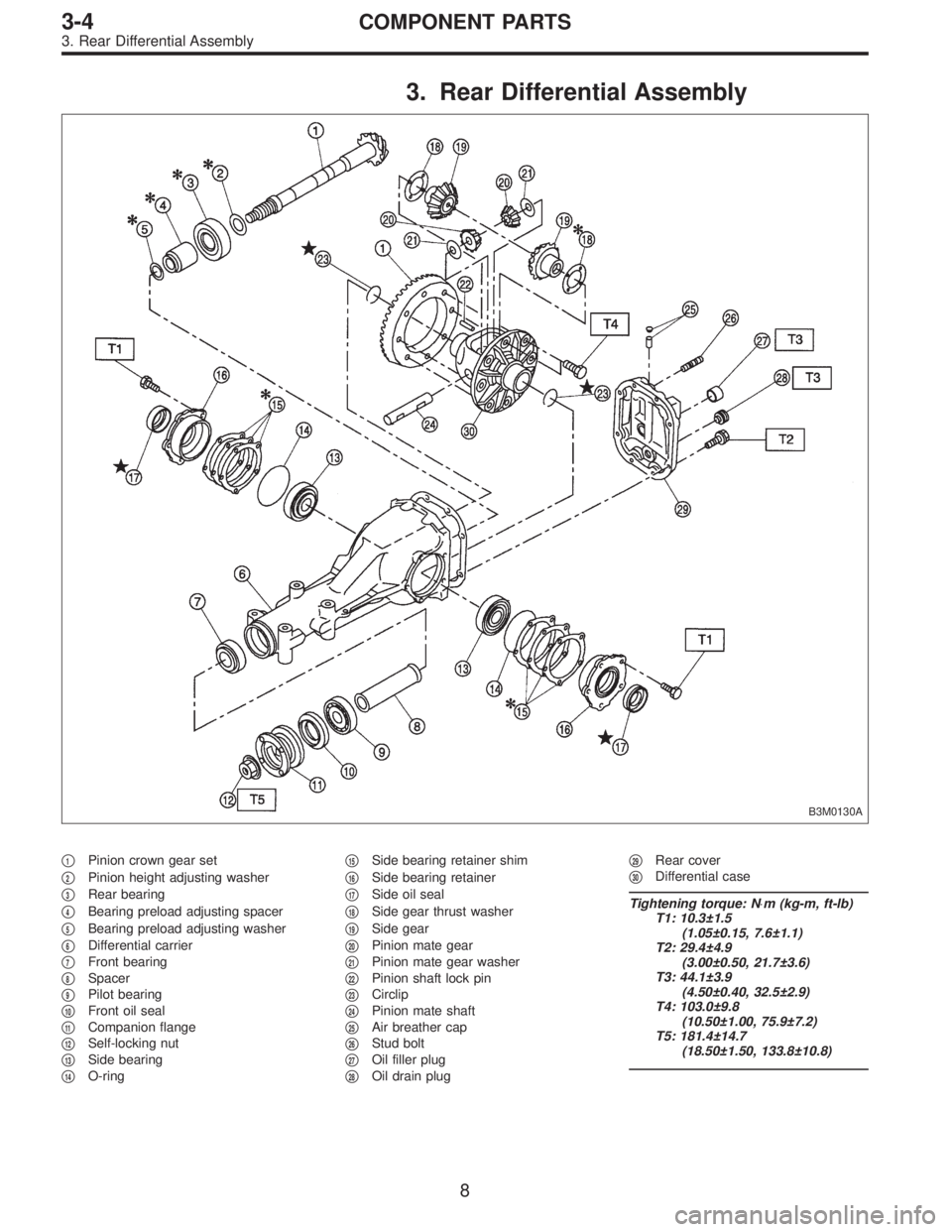
3. Rear Differential Assembly
B3M0130A
�1Pinion crown gear set
�
2Pinion height adjusting washer
�
3Rear bearing
�
4Bearing preload adjusting spacer
�
5Bearing preload adjusting washer
�
6Differential carrier
�
7Front bearing
�
8Spacer
�
9Pilot bearing
�
10Front oil seal
�
11Companion flange
�
12Self-locking nut
�
13Side bearing
�
14O-ring�
15Side bearing retainer shim
�
16Side bearing retainer
�
17Side oil seal
�
18Side gear thrust washer
�
19Side gear
�
20Pinion mate gear
�
21Pinion mate gear washer
�
22Pinion shaft lock pin
�
23Circlip
�
24Pinion mate shaft
�
25Air breather cap
�
26Stud bolt
�
27Oil filler plug
�
28Oil drain plug�
29Rear cover
�
30Differential case
Tightening torque: N⋅m (kg-m, ft-lb)
T1: 10.3±1.5
(1.05±0.15, 7.6±1.1)
T2: 29.4±4.9
(3.00±0.50, 21.7±3.6)
T3: 44.1±3.9
(4.50±0.40, 32.5±2.9)
T4: 103.0±9.8
(10.50±1.00, 75.9±7.2)
T5: 181.4±14.7
(18.50±1.50, 133.8±10.8)
8
3-4COMPONENT PARTS
3. Rear Differential Assembly
Page 1048 of 3342
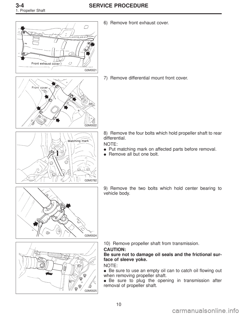
G3M0021
6) Remove front exhaust cover.
G3M0022
7) Remove differential mount front cover.
G3M0782
8) Remove the four bolts which hold propeller shaft to rear
differential.
NOTE:
�Put matching mark on affected parts before removal.
�Remove all but one bolt.
G3M0024
9) Remove the two bolts which hold center bearing to
vehicle body.
G3M0025
10) Remove propeller shaft from transmission.
CAUTION:
Be sure not to damage oil seals and the frictional sur-
face of sleeve yoke.
NOTE:
�Be sure to use an empty oil can to catch oil flowing out
when removing propeller shaft.
�Be sure to plug the opening in transmission after
removal of propeller shaft.
10
3-4SERVICE PROCEDURE
1. Propeller Shaft
Page 1051 of 3342
G3M0027
4) Align matching marks and connect front and rear pro-
peller shafts.
Tightening torque:
27.9±4.4 N⋅m (2.85±0.45 kg-m, 20.6±3.3 ft-lb)
G3M0024
F: INSTALLATION
1) Insert sleeve yoke into transmission and attach center
bearing to vehicle body.
Tightening torque:
52±5 N⋅m (5.3±0.5 kg-m, 38.3±3.6 ft-lb)
G3M0782
2) Align matching marks and connect flange yoke and rear
differential.
Tightening torque:
31±8 N⋅m (3.2±0.8 kg-m, 23.1±5.8 ft-lb)
G3M0022
3) Install differential mount front cover.
Tightening torque:
88±10 N⋅m (9.0±1.0 kg-m, 65±7 ft-lb)
G3M0021
4) Install front exhaust cover.
5) Install rear exhaust pipe and muffler.
13
3-4SERVICE PROCEDURE
1. Propeller Shaft
Page 1052 of 3342
2. Rear Differential
A: ON-CAR SERVICE
1. FRONT OIL SEAL
1) Disconnect ground cable from battery.
2) Move selector lever or gear shift lever to“N”.
3) Release the parking brake.
B3M0316A
4) Remove oil drain plug, and drain gear oil.
G3M0024
5) Jack-up rear wheels and support the vehicle body with
sturdy racks.
6) Remove propeller shaft from body.
[W1B0].>
CAUTION:
Wrap metal parts with a cloth or rubber material to
prevent damage from adjacent metal parts.
G3M0034
7) Remove self-locking nut while holding companion
flange with ST.
ST 498427200 FLANGE WRENCH
G3M0035
8) Extract companion flange with a puller.
14
3-4SERVICE PROCEDURE
2. Rear Differential
Page 1053 of 3342
G3M0036
9) Remove oil seal using ST.
ST 499705401 PULLER ASSY
G3M0037
10) Fit a new oil seal using ST.
ST 498447120 OIL SEAL INSTALLER
G3M0034
11) Install companion flange.
12) Tighten self-locking nut within the specified torque
range so that the turning resistance of companion flange
becomes the same as that before replacing oil seal.
ST 498427200 FLANGE WRENCH
CAUTION:
Use a new self-locking nut.
Tightening torque:
181.4±14.7 N⋅m (18.50±1.50 kg-m, 133.8±10.8 ft-lb)
13) Reassembling procedure hereafter is the reverse of
the disassembling.
15
3-4SERVICE PROCEDURE
2. Rear Differential

 Align matching marks and connect front and rear pro-
peller shafts.
Tightening torque:
27.9±4.4 N⋅m (2.85±0.45 kg-m, 20.6±3.3 ft-lb)
G3M0024
F: INSTALLATION
1) Insert sleeve yoke into")
 Disconnect ground cable from battery.
2) Move selector lever or gear shift lever to“N”.
3) Release the parking brake.
B3M0316A
4) Remove")
 Remove oil seal using ST.
ST 499705401 PULLER ASSY
G3M0037
10) Fit a new oil seal using ST.
ST 498447120 OIL SEAL INSTALLER
G3M0034
11) Install companion flange.
12) Tighten self-locking nu")