Page 1905 of 3342

LED No. Signal name Display
1——
2 AEC signal EC
3 EAM signal AM
4 AEB signal EB
5——
6 AET signal ET
7Engine torque control
signalTR
8——
9——
0——
—EC AM EB—
ET TR———
1
2345
67890
43. FUNCTION MODE: FA2
—ON↔OFF SIGNAL—
Requirement for LED“ON”.
LED No. 2 ECM entered the AEC signal emitted from
TCS C/M.
LED No. 3 EAM signal goes out.
LED No. 4 ECM entered the AEB signal emitted from
TCS C/M.
LED No. 6 ECM entered the AET signal emitted from
TCS C/M.
LED No. 7 ECM entered the torque control signal emit-
ted from TCM.
LED No. Signal name Display
1——
2——
3——
4——
5——
6——
7Pressure sources switching
solenoid valveBR
8——
9——
0——
—————
—BR———
1
2345
67890
44. FUNCTION MODE: FA3
—ON↔OFF SIGNAL—
Requirement for LED“ON”.
LED No. 7 Pressure sources switching solenoid valve is
in function.
NOTE:
When LED No. 7 blinks with the test mode connector con-
nected and the ignition switch turned to ON, the corre-
sponding part is functioning properly.
54
2-7ON-BOARD DIAGNOSTICS II SYSTEM
3. Diagnosis System
Page 1906 of 3342

LED No. Signal name Display
1 Catalyst CA
2 EGR system E1
3California model
identification signalFC
4——
5——
6——
7——
8 Rear oxygen sensor signal OR
9 Front oxygen sensor signal O2
0——
CA E1 FC——
——OR O2—
1
2345
67890
45. FUNCTION MODE: FA4
—ON↔OFF SIGNAL—
Requirement for LED“ON”.
LED No. 1 Diagnosis of catalyzer is finished.
LED No. 2 Diagnosis of EGR system is finished.
LED No. 3 Vehicle is Federal specifications.
LED No. 8 Rear oxygen sensor mixture ratio is rich.
LED No. 9 Front oxygen sensor mixture ratio is rich.
LED No. Signal name Display
1——
2——
3——
4——
5——
6 Vent control solenoid valve AL
7 EGR solenoid valve ER
8Pressure control solenoid
valvePC
9——
0——
—————
AL ER PC——
1
2345
67890
46. FUNCTION MODE: FA5
—ON↔OFF SIGNAL—
Requirement for LED“ON”.
LED No. 6 Vent control solenoid valve is in function.
LED No. 7 EGR solenoid valve is in function.
LED No. 8 Pressure control solenoid valve is in func-
tion.
NOTE:
When LED No. 6, 7 and 8 blinks with the test mode con-
nector connected and the ignition switch turned to ON, the
corresponding part is functioning properly.
55
2-7ON-BOARD DIAGNOSTICS II SYSTEM
3. Diagnosis System
Page 1907 of 3342
Current trouble code indicated by on-board
diagnostics after clear memo")
47. FB MODE FOR ENGINE
Function mode Abbreviation Contents Contents of display Page
FB0 INSPECT On-board diagnostics (Inspection)Current trouble code indicated by on-board
diagnostics after clear memory.65
FB1 OBD On-board diagnostics (Read data)Current trouble code indicated by on-board
diagnostics.37
FB2LOAD�F Load data
�Freeze frame data
�Data stored at the time of trouble
occurrence, is shown on display.38
TW�F Engine coolant temperature signal
ALPH�F Throttle position signal
KBLR�F Long term fuel trim
MANI�FIntake manifold absolute pressure
signal
EREV�F Engine speed signal
VSP�F Vehicle speed signal
FB3QA�F (P0100) Mass air flow signal
�Freeze frame data
�Data stored at the time of trouble
occurrence, is shown on display.40
PS�F (P0105) Pressure signal
PR�F (P0106) Pressure signal
TW�F (P0115) Engine coolant temperature signal
THV�F (P0120) Throttle position signal
EGR (P0403) EGR control solenoid valve signal
CPC (P0443) Purge control solenoid valve signal
STSW (P1100) Start switch signal
BR1 (P1102)Pressure sources switching sole-
noid valve signal
FAN1 (P1500) Radiator fan relay 1 signal
48. FC MODE FOR ENGINE
Function mode Abbreviation Contents Contents of display Page
FC0 MEMORY CLR Back-up memory clearFunction of clearing trouble code stored in
memory.64
49. FD MODE FOR ENGINE
Function mode Abbreviation Contents Contents of display Page
FD01 FUEL PUMP
Compulsory valve operation checkFunction of checking operation of fuel
pump relay, purge control solenoid valve,
radiator fan relay, A/C relay, EGR control
solenoid valve, pressure control solenoid
valve, vent control solenoid valve and pres-
sure sources switching solenoid valve.71
FD02 CPC SOL
FD03 RAD FAN
FD04 A/C RELAY
FD05 EGR SOL
FD07 PCV SOL
FD08 VENT SOL
FD10 BR SOL
NOTE:
Because ASV solenoid valve, FICD solenoid valve and air
injection system diagnosis solenoid valve are not installed,
FD06, FD09 and FD11 will be displayed but non-functional.
56
2-7ON-BOARD DIAGNOSTICS II SYSTEM
3. Diagnosis System
Page 1908 of 3342
H2M1150
50. READ CURRENT DATA SHOWN ON DISPLAY
FOR AT. (FUNCTION MODE)
1) Select AT mode using function key.
Press the function key [/], and change to AT mode.
H2M1151
2) Press the function key [0].
G3M0152
3) Designate mode using function key.
(Example: Press [F] [0] [2] [ENT] in that order.)
4) Ensure data of input or output signal is shown.
57
2-7ON-BOARD DIAGNOSTICS II SYSTEM
3. Diagnosis System
Page 1909 of 3342
51. READ DATA FUNCTION KEY LIST FOR AT
Function mode Contents Abbr. Unit
F00 Mode display E-4AT—
F01 Battery voltage VB V
F02 Vehicle speed sensor 1 signal VSP1 m/h
F03 Vehicle speed sensor 1 signal VSP1 km/h
F04 Vehicle speed sensor 2 signal VSP2 m/h
F05 Vehicle speed sensor 2 signal VSP2 km/h
F06 Engine speed EREV rpm
F07 ATF temperature sensor signal ATFT deg F
F08 ATF temperature sensor signal ATFT deg C
F09 Throttle position sensor signal THV V
F10 Gear position GEAR—
F11 Line pressure duty ratio PLDTY %
F12 Lock-up duty ratio LUDTY %
F13 AWD duty ratio 4WDTY %
F14 Throttle position sensor power supply voltage THVCC V
F15 Mass air flow sensor signal AFM V
58
2-7ON-BOARD DIAGNOSTICS II SYSTEM
3. Diagnosis System
Page 1910 of 3342
B2M1046
52. FUNCTION MODE: F00
—MODE DISPLAY—
SPECIFIED DATA:
Data at the left should be indicated.
Probable cause (if outside“specified data”)
1. Communication failure
(No communication method can be confirmed
with power ON.)
�(1)Check loose or poor connectors, or
shortcircuit.
(2) Check type of cartridge.
2. Vehicle types cannot be identified (due to
communication failure).�Check improper cartridge.
Replace with proper one.
OBD0673
53. FUNCTION MODE: F01
—BATTERY VOLTAGE (VB)—
CONDITION:
(1) Ignition switch ON
(2) Engine idling after warm-up
SPECIFIED DATA:
(1) 12±1 V
(2) 13±1 V
1. Battery�Check battery voltage and specific gravity of
electrolyte.
2. Charging system�(1)Measure regulating voltage under no loads.
(2) Check generator (as a single unit).
59
2-7ON-BOARD DIAGNOSTICS II SYSTEM
3. Diagnosis System
Page 1914 of 3342

LED No. Signal name Display
1 FWD switch FF
2 Kick-down switch KD
3——
4——
5 Brake switch BR
6 ABS switch AB
7 Cruise control set CR
8 Power switch PW
9——
10——
FF KD——BR
AB CR PW——
1
2345
678910
65. FUNCTION MODE: FA0
—ON↔OFF SIGNAL—
Requirement for LED“ON”.
LED No. 1 Fuse is installed in FWD switch.
LED No. 2 Kick-down switch is turned ON. (Europe and
General models only)
LED No. 5 Brake pedal is depressed.
LED No. 6 ABS signal is entered.
LED No. 7 Cruise control is set.
LED No. 8 Power switch is turned ON. (Europe and
General models only)
LED No. Signal name Display
1 N/P range switch NP
2 R range switch RR
3 D range switch RD
4 3 range switch R3
5 2 range switch R2
6 1 range switch R1
7 Diagnosis switch SS
8——
9——
10——
NP RR RD R3 R2
R1 SS———
1
2345
678910
66. FUNCTION MODE: FA1
—ON↔OFF SIGNAL—
Requirement for LED“ON”.
LED No. 1“N”or“P”range is selected.
LED No. 2“R”range is selected.
LED No. 3“D”range is selected.
LED No. 4“3”range is selected.
LED No. 5“2”range is selected.
LED No. 6“1”range is selected.
LED No. 7 Diagnosis connector is connected.
63
2-7ON-BOARD DIAGNOSTICS II SYSTEM
3. Diagnosis System
Page 1915 of 3342
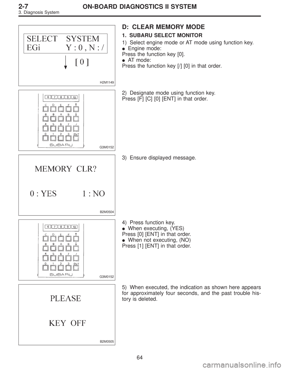
H2M1149
D: CLEAR MEMORY MODE
1. SUBARU SELECT MONITOR
1) Select engine mode or AT mode using function key.
�Engine mode:
Press the function key [0].
�AT mode:
Press the function key [/] [0] in that order.
G3M0152
2) Designate mode using function key.
Press [F] [C] [0] [ENT] in that order.
B2M0504
3) Ensure displayed message.
G3M0152
4) Press function key.
�When executing, (YES)
Press [0] [ENT] in that order.
�When not executing, (NO)
Press [1] [ENT] in that order.
B2M0505
5) When executed, the indication as shown here appears
for approximately four seconds, and the past trouble his-
tory is deleted.
64
2-7ON-BOARD DIAGNOSTICS II SYSTEM
3. Diagnosis System
![SUBARU LEGACY 1997 Service Repair Manual H2M1150
50. READ CURRENT DATA SHOWN ON DISPLAY
FOR AT. (FUNCTION MODE)
1) Select AT mode using function key.
Press the function key [/], and change to AT mode.
H2M1151
2) Press the function key [0].
G](/manual-img/17/57434/w960_57434-1907.png "SUBARU LEGACY 1997 Service Repair Manual H2M1150
50. READ CURRENT DATA SHOWN ON DISPLAY
FOR AT. (FUNCTION MODE)
1) Select AT mode using function key.
Press the function key [/], and change to AT mode.
H2M1151
2) Press the function key [0].
G")


1. Communication failure
(No communication metho")