Page 195 of 3342
![SUBARU LEGACY 1997 Service Repair Manual
BRAKES
[ABS
5
.31
TYPE]
[T10AG5]
4-4d
10
.
DiagnosticsChart
with
Select
Monitor
1997
(F00)
ABS
4WD
"
AT
H4M
11171
G-SENS
(F
10)
2
.30
V
sannos271
10AG1
HECK
I
US
G
SE
ECT,MONT
OR
OF
ABSC](/manual-img/17/57434/w960_57434-194.png "SUBARU LEGACY 1997 Service Repair Manual
BRAKES
[ABS
5
.31
TYPE]
[T10AG5]
4-4d
10
.
DiagnosticsChart
with
Select
Monitor
1997
(F00)
ABS
4WD
\"
AT
H4M
11171
G-SENS
(F
10)
2
.30
V
sannos271
10AG1
HECK
I
US
G
SE
ECT,MONT
OR
OF
ABSC")
BRAKES
[ABS
5
.31
TYPE]
[T10AG5]
4-4d
10
.
DiagnosticsChart
with
Select
Monitor
1997
(F00)
ABS
4WD
"
AT
H4M
11171
G-SENS
(F
10)
2
.30
V
sannos271
10AG1
HECK
I
US
G
SE
ECT,MONT
OR
OF
ABSCM&H/U
1)
Press
[F],
[0]
and
[0]
on
the
select
monitor
.
2)
Read
the
select
monitor
display
.
CH~K
:
Is
an
ABSCM&HlU
for
4WD
model
installed
on
a
FWD
model?
Replace
ABSCM&H/U
.
No
:
Go
to
step
10AG2
.
I10AG2
CHECK
OUTPUT
I
SELECT
MONITOR
F
G
SENSOR
USING
1)
Press
[F],
[1]
and
[0]
on
the
select
monitor
.
2)
Read
the
select
monitor
display
.
K
:
Is
theindicated
reading
between
2
.1
and
2
.5
V
when
the
G
sensor
is
in
horizontal
posi-
tion?
,rE$
:
Go
to
step
10AG3
.
Go
to
step
10AG6
.
I
10AG3
I
CHECK
POOR
CONTACT
IN
CONNECTORS
.
CHECK
:
Is
there
poor
contact
in
connector
between
ABSCM&HIU
and
G
sensor?
<
Ref
.
to
FORE-
WORD
[T3C1]
.*10
>
Repair
connector
.
No
:
Go
tostep
10AG4
.
10AG4
CHECK
ABSCM&HlU
.
1)
Connect
all
connectors
.
2)
Erase
the
memory
.
3)
Perform
inspection
mode
.
4)
Read
out
the
trouble
code
.
c
:
Is
the
same
trouble
code
as
in
thecurrent
diagnosis
still
being
output?
Replace
ABSCM&H1U
.
No
:
Go
to
step
i0AG5
.
10AG5
CHECK
ANY
I
APPEARANCE
.THER
TROUBLE
CODES
CHECK
:
Are
other
trouble
codes
being
output?
Proceed
withthe
diagnosis
corresponding
to
the
trouble
code
.
A
temporary
poor
contact
.
187
Page 196 of 3342
![SUBARU LEGACY 1997 Service Repair Manual
4-4d
RIonGS1
BRAKES
[ABS
5
.31
TYPE]
10
.
Diagnostics
Chart
with
Select
Monitor
FR
(
FES
)
0
km/
h
84M0977
FL(FE6)
0
km/
h
B4M0978
RR
(
FE7
)
0
km/
h
84M0379
RL
(FE8)
0
km/
h
84M0980
G-](/manual-img/17/57434/w960_57434-195.png "SUBARU LEGACY 1997 Service Repair Manual
4-4d
RIonGS1
BRAKES
[ABS
5
.31
TYPE]
10
.
Diagnostics
Chart
with
Select
Monitor
FR
(
FES
)
0
km/
h
84M0977
FL(FE6)
0
km/
h
B4M0978
RR
(
FE7
)
0
km/
h
84M0379
RL
(FE8)
0
km/
h
84M0980
G-")
4-4d
RIonGS1
BRAKES
[ABS
5
.31
TYPE]
10
.
Diagnostics
Chart
with
Select
Monitor
FR
(
FES
)
0
km/
h
84M0977
FL(FE6)
0
km/
h
B4M0978
RR
(
FE7
)
0
km/
h
84M0379
RL
(FE8)
0
km/
h
84M0980
G-SENS
(FE14)
3
.70
V
B4M0981
10AG6
CHECK
FREEZE
FRAME
DATA
.
1)
Press
[F],
[E]
and
[5]
on
the
select
monitor
.
2)
Read
the
select
monitor
display
.
CHECK
:
Is
the
reading
indicated
on
monitor
display0
km?
C,rES~
:
Go
tostep
10AG7
.
No
:
Go
tostep
10AG15
.
1
10AG7
I
CHECK
FREEZE
FRAME
DATA
.
1)
Press
the
scroll
keyso
that
FE6
appears
on
the
moni-
tor
display
.
2)
Read
the
select
monitor
display
.
CHECK
:
Is
the
reading
indicated
on
monitor
display
0
km?
~
:
Go
to
step
10AG8
.
No
:
Go
to
step
10AG15
.
J
10AG8
I
CHECK
FREEZE
FRAME
DATA
.
1)
Press
the
scroll
key
so
that
FE7
appears
on
the
moni-
tor
display
.
2)
Read
the
select
monitor
display
.
ELK
:
Is
the
reading
indicated
on
monitor
display0
km?
Go
tostep
10AG9
.
No
:
Go
tostep
10AG15
.
10AG9
CHECK
FREEZE
FRAME
DATA
.
1)
Press
the
scroll
keyso
that
FE8
appears
on
the
moni-
tor
display
.
2)
Read
the
select
monitor
display
.
ECK
:
Is
the
reading
indicated
on
monitor
display0
km?
Go
to
step
10AG10
.
No
:
Go
to
step
10AG15
.
1
10AG10
I
CHECK
FREEZE
FRAME
DATA
.
1)
Press
the
scroll
keyso
that
FE14
appears
on
the
mon-
itor
display
.
2)
Read
the
select
monitor
display
.
CHECK
:
Is
the
reading
indicated
on
monitor
display
more
than3
.65
V?
Go
to
step
10AG11
.
No
:
Go
to
step
10AG15
.
188
Page 202 of 3342
![SUBARU LEGACY 1997 Service Repair Manual
BRAKES
[ABS
5
.31
TYPE]
(T10AH3]
4-4d
10
.
Diagnostics
Chart
withSelect
Monitor
G-SENS
(F
10)
2
.30
V
sannos271
F49
1
23
4
5
6
.1
7
1
8
1
9
01112131415
16171
192C
12
2324
2526
728293031
11
D](/manual-img/17/57434/w960_57434-201.png "SUBARU LEGACY 1997 Service Repair Manual
BRAKES
[ABS
5
.31
TYPE]
(T10AH3]
4-4d
10
.
Diagnostics
Chart
withSelect
Monitor
G-SENS
(F
10)
2
.30
V
sannos271
F49
1
23
4
5
6
.1
7
1
8
1
9
01112131415
16171
192C
12
2324
2526
728293031
11
D")
BRAKES
[ABS
5
.31
TYPE]
(T10AH3]
4-4d
10
.
Diagnostics
Chart
withSelect
Monitor
G-SENS
(F
10)
2
.30
V
sannos271
F49
1
23
4
5
6
.1
7
1
8
1
9
01112131415
16171
192C
12
2324
2526
728293031
11
D
_
V
B4M1263A
I10AH1
CHECK
OUTPUT
(SELECT
MONITORF
G
SENSOR
USING
1)
Press
[F],
[1]
and
[0]
on
the
select
monitor
.
2)
Read
the
select
monitor
display
.
CHECK
;
Is
theindicated
reading
between
2
.1
and
2
.5
V
when
the
G
sensor
is
in
horizontal
posi-
tion?
Replace
ABSCM&H/U
.
No
:
Go
tostep
10AH2
.
1
10AH2
I
CHECK
BATTERY
SHORT
OF
HARNESS
.
1)
Turn
ignition
switch
to
OFF
.
2)
Remove
console
box
.
3)
Disconnect
connector
from
G
sensor
.
4)
Disconnect
connector
from
ABSCM&H/U
.
5)
Measure
voltage
between
ABSCM&H/U
connector
and
chassis
ground
.
Connector
&
terminal
(F49)
No
.
6
(+)
-
Chassis
ground
(
)
:
CHECK
;
Is
thevoltage
less
than1
V?
Go
tostep
10AH3
.
No
:
Repair
harness
between
G
sensor
and
ABSCM&H/U
.
1
10AH3
I
CHECK
BATTERY
SHORT
OFHARNESS
.
1)
Turn
ignition
switch
to
ON
.
2)
Measure
voltage
between
ABSCM&H/U
connector
and
chassis
ground
.
Connector
&
terminal
(F49)
No
.
6
(+)
-
Chassis
ground
(
)
:
CHECK
;
Is
the
voltage
less
than
1
V?
vES
:
Go
tostep
10AH4
.
No
:
Repair
harness
between
G
sensor
and
ABSCM&H/U
.
195
Page 205 of 3342
![SUBARU LEGACY 1997 Service Repair Manual
BRAKES
[ABS
5
.3i
TYPE]
R1oaia1
4-4d
10
.
Diagnostics
Chart
with
Select
Monitor
G-
SENS
(F
10)
2
.30
V
B4M0927
I10A11
CHECK
OUTPUT
(SELECT
MONITORF
G
SENSOR
USING
1)
Press
[F],
[1]
and
[0]
on](/manual-img/17/57434/w960_57434-204.png "SUBARU LEGACY 1997 Service Repair Manual
BRAKES
[ABS
5
.3i
TYPE]
R1oaia1
4-4d
10
.
Diagnostics
Chart
with
Select
Monitor
G-
SENS
(F
10)
2
.30
V
B4M0927
I10A11
CHECK
OUTPUT
(SELECT
MONITORF
G
SENSOR
USING
1)
Press
[F],
[1]
and
[0]
on")
BRAKES
[ABS
5
.3i
TYPE]
R1oaia1
4-4d
10
.
Diagnostics
Chart
with
Select
Monitor
G-
SENS
(F
10)
2
.30
V
B4M0927
I10A11
CHECK
OUTPUT
(SELECT
MONITORF
G
SENSOR
USING
1)
Press
[F],
[1]
and
[0]
on
the
select
monitor
.
2)
Read
the
select
monitor
display
.
CHECK
:
Is
theindicated
reading
2
.3
±
0
.2
V
when
the
G
sensor
isin
horizontal
position?
Go
to
step
10AI2
.
No
:
Go
to
step
10A16
.
2
I
CHECK
POOR
CONTACT
IN
CONNECTORS
.
Turn
ignition
switch
to
OFF
.
CHECK
:
Is
there
poor
contact
in
connector
between
A
.BSCM&HIU
and
G
sensor?
<
Ref
.
to
FORE-
WORD
(T3C1]
.*10
>
Repair
connector
.
No
:
Go
to
step
10AI3
.
diagnosis
still
being
output?
,rES
:
Replace
ABSCM&H/U
.
No
:
Go
to
step
10AI4
.
10A13
I
CHECK
ABSCM&H/U
.
1)
Connect
all
connectors
.
2)
Erase
the
memory
.
3)
Perform
inspection
mode
.
4)
Read
outthe
trouble
code
.
CHECK
:
Is
the
same
trouble
code
as
in
the
current
10A14
I
CHECK
ANY
OTHER
TROUBLE
CODES
APPEARANCE
.
Are
other
trouble
codes
being
output?
Proceed
with
the
diagnosis
corresponding
to
the
trouble
code
.
No
:
A
temporary
poor
contact
.
199
Page 210 of 3342
![SUBARU LEGACY 1997 Service Repair Manual
BRAKES
[ABS
5
.3i
TYPE]
[T10AJ4]
4-4d
10
.
Diagnostics
Chart
with
Select
Monitor
G-SENS
(F
10)
2
.30
v
B4M0927
I
Front
r
0
B4M0917A
0
Front
a
B4M0918A
I10AJ1
CHECK
(
TURN
NG
LL
FOUR
WHEE](/manual-img/17/57434/w960_57434-209.png "SUBARU LEGACY 1997 Service Repair Manual
BRAKES
[ABS
5
.3i
TYPE]
[T10AJ4]
4-4d
10
.
Diagnostics
Chart
with
Select
Monitor
G-SENS
(F
10)
2
.30
v
B4M0927
I
Front
r
0
B4M0917A
0
Front
a
B4M0918A
I10AJ1
CHECK
(
TURN
NG
LL
FOUR
WHEE")
BRAKES
[ABS
5
.3i
TYPE]
[T10AJ4]
4-4d
10
.
Diagnostics
Chart
with
Select
Monitor
G-SENS
(F
10)
2
.30
v
B4M0927
I
Front
r
0
B4M0917A
0
Front
a
B4M0918A
I10AJ1
CHECK
(
TURN
NG
LL
FOUR
WHEELS
FOR
FREE
CHECK
:
Have
the
wheels
been
turned
freely
such
as
when
the
vehicle
is
lifted
up,
or
operatedon
a
rolling
road?
,rES
:
The
ABS
is
normal
.
Erase
the
trouble
code
.
No
:
Go
to
step
10AJ2
.
J2
CHECK
OUTPUT
I
SEL
CT
MONITORF
G
SENSOR
USING
1)
Press
[F],
[1]
and
[0]
on
the
select
monitor
.
2)
Read
the
select
monitor
display
.
CHECK
:
Is
theindicated
reading
between
2
.1
and
2
.5
Vwhen
the
vehicle
is
in
horizontalposition?
ves
:
Go
to
step
10AJ3
.
No
:
Go
to
step
10AJ8
.
I10AJ3
CHECK
OUTPUT
(SELECT
MONITORF
G
SENSOR
USING
1)
Turn
ignition
switchto
OFF
.
2)
Remove
console
box
.
3)
Remove
G
sensorfrom
vehicle
.
(Do
notdisconnect
connector
.)
4)
Turn
ignition
switch
to
ON
.
5)
Press
[F],
[1]
and
[0]
on
the
select
monitor
.
6)
Read
the
select
monitor
display
.
CHECK
;
Is
theindicated
reading
between
3
.7
and
4
.1
V
when
G
sensor
is
inclined
forwards
to
90°?
Go
to
step
10AJ4
.
No
:
Replace
G
sensor
.
I10AJ4
CHECK
OUTPUT
I
SELECT
MONITOR
F
G
SENSOR
USING
Read
the
select
monitor
display
.
CHECK
:
Is
theindicated
reading
between
0
.5
and
0
.9
Vwhen
G
sensor
is
inclined
backwards
to
90°?
vES
:
Go
to
step
10AJ5
.
No
:
Replace
G
sensor
.
205
Page 1366 of 3342
B4M0997
5) The message shown in the figure is displayed.
B4M0998
6) The message shown in the figure is displayed as fol-
lows:
(1) When using the brake tester, depress brake pedal
with braking force of 981 N (100 kg, 221 lb).
(2) When using the pressure gauge, depress brake
pedal so as to make the pressure gauge indicate 3,432
kPa (35 kg/cm
2, 498 psi).
CAUTION:
Do not depress the clutch pedal.
B4M0999
7) When the message shown in the figure is displayed,
press ENT key.
8) Check points will be displayed on select monitor.
B4M1000
9) When ABS sequence control cannot be started (by sys-
tem malfunction, etc.), the message shown in the figure will
be displayed.
NOTE:
Read the trouble codes. Repair faulty parts.
B4M1030
10) After completion of ABS sequence control, turn ignition
switch OFF.
84
4-4SERVICE PROCEDURE
15. Hydraulic Unit for ABS System (ABS 5.3 Type)
Page 1375 of 3342
 No. 2 (+)—No.1(�)
Is voltage 3.9±0.2 V when G sensor is
inclined forwards to 90°?
: Go to next.
: Replace G sensor.
B4M0918A
: Connector & terminal
(P9) No. 2")
B4M0917A
: Connector & terminal
(P9) No. 2 (+)—No.1(�)
Is voltage 3.9±0.2 V when G sensor is
inclined forwards to 90°?
: Go to next.
: Replace G sensor.
B4M0918A
: Connector & terminal
(P9) No. 2 (+)—No.1(�)
Is voltage 0.7±0.2 V when G sensor is
inclined backwards to 90°?
: G sensor is normal.
: Replace G sensor.
2. USING SELECT MONITOR
1) Turn ignition switch to OFF.
2) Connect select monitor connector to data link connec-
tor.
3) Turn select monitor into ABS mode.
B4M0927
4) Press F,1and 0on the select monitor.
5) Rear the select monitor display.
: Is the indicated reading 2.3±0.2 V when the
vehicle is in horizontal position?
: Go to next step 6).
: Replace G sensor.
6) Remove console box.
7) Remove G sensor from vehicle. (Do not disconnect
connector.)
B4M0917A
8) Read the select monitor display.
: Is the indicated reading 3.9±0.2 V when G
sensor is inclined forwards to 90°?
: Go to next.
: Replace G sensor.
91
4-4SERVICE PROCEDURE
17. G Sensor for ABS System (ABS 5.3 Type)
Page 1387 of 3342
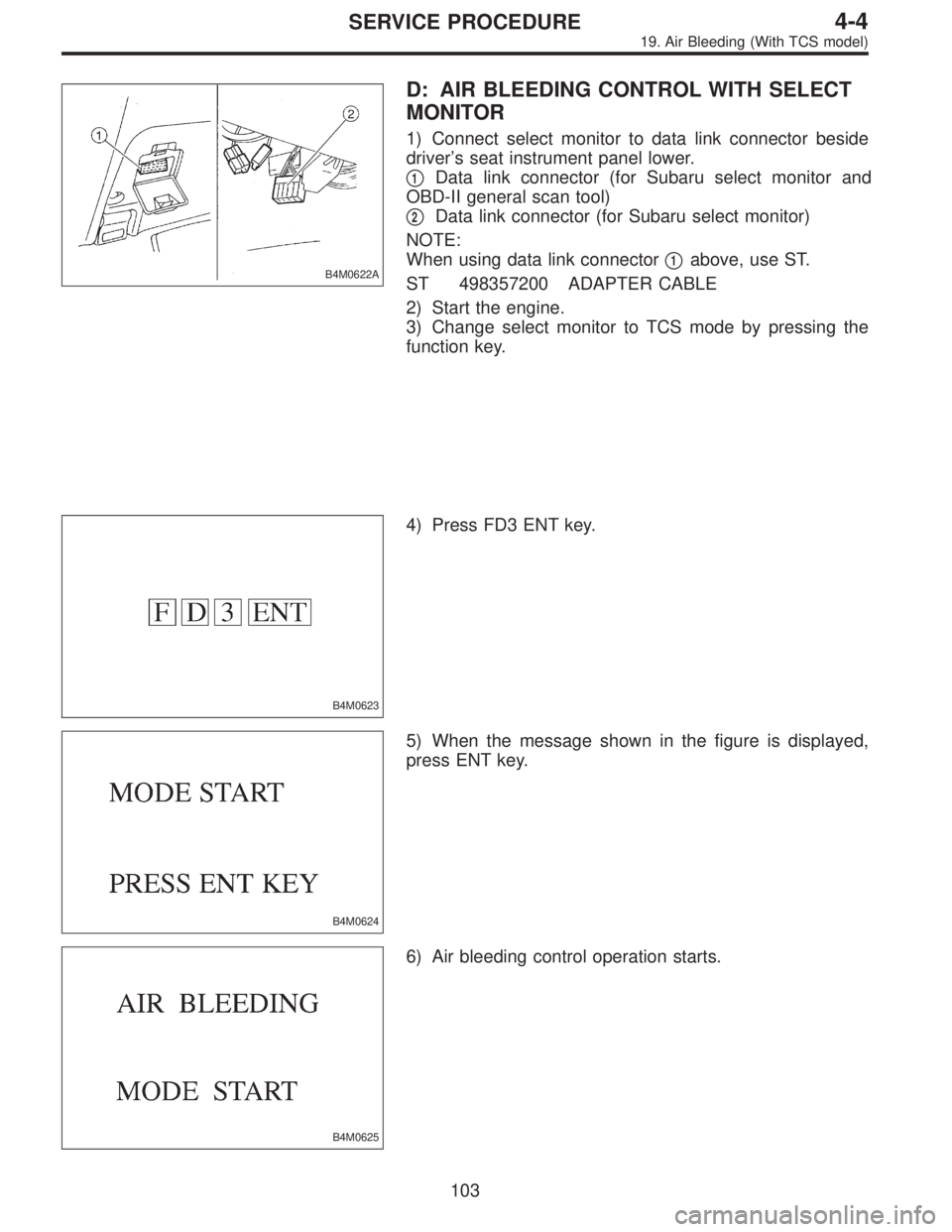
B4M0622A
D: AIR BLEEDING CONTROL WITH SELECT
MONITOR
1) Connect select monitor to data link connector beside
driver’s seat instrument panel lower.
�
1Data link connector (for Subaru select monitor and
OBD-II general scan tool)
�
2Data link connector (for Subaru select monitor)
NOTE:
When using data link connector�
1above, use ST.
ST 498357200 ADAPTER CABLE
2) Start the engine.
3) Change select monitor to TCS mode by pressing the
function key.
B4M0623
4) Press FD3 ENT key.
B4M0624
5) When the message shown in the figure is displayed,
press ENT key.
B4M0625
6) Air bleeding control operation starts.
103
4-4SERVICE PROCEDURE
19. Air Bleeding (With TCS model)
 The message shown in the figure is displayed.
B4M0998
6) The message shown in the figure is displayed as fol-
lows:
(1) When using the brake tester, depress brake pedal
with braking force o")