Page 1399 of 3342
 Under the TCS sequence control, after the hydraulic
unit solenoid valve is driven, the operation of the hydraulic
unit can be checked by means of the brake tester or pres-
s")
F: TCS SEQUENCE CONTROL
1) Under the TCS sequence control, after the hydraulic
unit solenoid valve is driven, the operation of the hydraulic
unit can be checked by means of the brake tester or pres-
sure gauge.
2) TCS sequence control can be started by diagnosis con-
nector or select monitor.
B4M0082C
1. OPERATIONAL GUIDELINES OF THE TCS
SEQUENCE CONTROL WITH DIAGNOSIS
CONNECTOR
1) Connect diagnosis terminals to terminal No. 4 of the
diagnosis connector beside driver seat heater unit.
2) Ignition switch is turned to ON.
3) Make sure only the start code (code 11) is shown in
normal condition.
NOTE:
When trouble codes are stored in memory, repair the faulty
parts.
4) Set the speed of all wheels at 10 km/h (6 MPH) or less.
5) Turn ignition switch OFF.
6) Start engine, and within 0.5 seconds after the ABS
warning light and TCS warning light go out, press TCS OFF
switch. Within 1.0 second thereafter, release and press the
switch again. Then, keep the switch pressed.
NOTE:
�When the TCS sequence control is set to on, the brake
pedal must not be depressed.
�Engine must operate.
�When TCS OFF switch is not depressed within 0.5 sec-
onds after ABS and TCS warning lights turn off, the trouble
code mode comes on.
7) After completion of TCS sequence control, turn ignition
switch OFF.
11 5
4-4SERVICE PROCEDURE
20. Hydraulic Unit for ABS/TCS System
Page 1411 of 3342
 Under the ABS sequence control, after the hydraulic
unit solenoid valve is driven, the operation of the hydraulic
unit can be checked by means of the brake tester or pres-
s")
D: ABS SEQUENCE CONTROL
1) Under the ABS sequence control, after the hydraulic
unit solenoid valve is driven, the operation of the hydraulic
unit can be checked by means of the brake tester or pres-
sure gauge.
2) ABS sequence control can be started by diagnosis con-
nector or select monitor.
B4M0082D
1. OPERATIONAL GUIDELINES OF THE ABS
SEQUENCE CONTROL WITH DIAGNOSIS
CONNECTOR
1) Connect diagnosis terminals to terminals No. 3 and No.
6 of the diagnosis connector beside driver’s seat heater
unit.
2) Set the speed of all wheels at 4 km/h (2 MPH) or less.
3) Turn ignition switch OFF.
4) Within 0.5 seconds after the ABS warning light goes
out, depress the brake pedal and hold it immediately after
ignition switch is turned to ON.
CAUTION:
Do not depress the clutch pedal.
NOTE:
�When the ignition switch is set to on, the brake pedal
must not be depressed.
�Engine must not operate.
5) After completion of ABS sequence control, turn ignition
switch OFF.
2. OPERATIONAL GUIDELINES OF THE ABS
SEQUENCE CONTROL WITH SELECT MONITOR
NOTE:
In the event of any trouble, the sequence control may not
be operative. In such a case, activate the sequence
control, referring to“OPERATIONAL GUIDELINES OF
THE ABS SEQUENCE CONTROL WITH DIAGNOSIS
CONNECTOR”.
1) Connect select monitor to data link connector beside
driver’s seat heater unit.
2) Turn ignition switch ON.
3) Put select monitor to ABS mode.
126
4-4SERVICE PROCEDURE
22. ABS Control Module and Hydraulic Control Unit (ABSCM&H/U) (ABS 5.3i Type)
Page 1413 of 3342
 After completion of ABS sequence control.
H4M1144
11) Press 0 key to start ABS sequence control again and
press 1 key to end.
3. CONDITIONS FOR COMPLETION OF ABS
SEQUENCE CONTROL
When the")
B4M1030
10) After completion of ABS sequence control.
H4M1144
11) Press 0 key to start ABS sequence control again and
press 1 key to end.
3. CONDITIONS FOR COMPLETION OF ABS
SEQUENCE CONTROL
When the following conditions develop, the ABS sequence
control stops and ABS operation is returned to the normal
control mode.
1) When the speed of at least one wheel reaches 10 km/h
(6 MPH).
2) When terminal No. 3 or No. 6 are separated from diag-
nosis terminals. (When select monitor is not used.)
3) When the brake pedal is released during sequence con-
trol and the braking lamp switch is set to off.
4) When brake pedal is depressed after ignition key is
turned to ON, and before ABS warning light goes out.
(When select monitor is not used.)
5) When brake pedal is not depressed after ignition key is
turned to ON, and within 0.5 seconds after ABS warning
light goes out. (When select monitor is not used.)
6) After completion of the sequence control.
7) When malfunction is detected. (When select monitor is
used.)
128
4-4SERVICE PROCEDURE
22. ABS Control Module and Hydraulic Control Unit (ABSCM&H/U) (ABS 5.3i Type)
Page 1453 of 3342
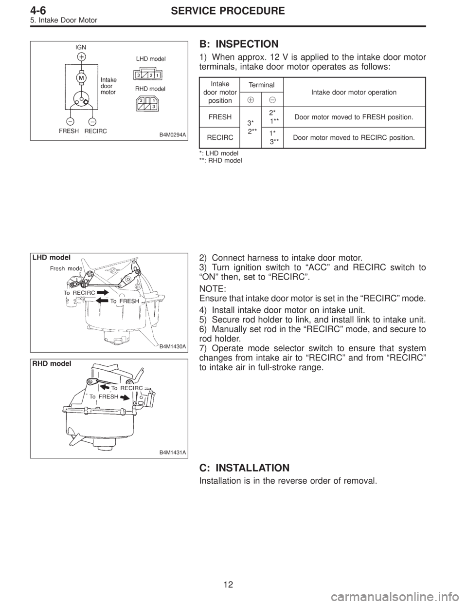
B4M0294A
B: INSPECTION
1) When approx. 12 V is applied to the intake door motor
terminals, intake door motor operates as follows:
Intake
door motor
positionTerminal
Intake door motor operation
��
FRESH
3*
2**2*
1**Door motor moved to FRESH position.
RECIRC1*
3**Door motor moved to RECIRC position.
*: LHD model
**: RHD model
B4M1430A
B4M1431A
2) Connect harness to intake door motor.
3) Turn ignition switch to“ACC”and RECIRC switch to
“ON”then, set to“RECIRC”.
NOTE:
Ensure that intake door motor is set in the“RECIRC”mode.
4) Install intake door motor on intake unit.
5) Secure rod holder to link, and install link to intake unit.
6) Manually set rod in the“RECIRC”mode, and secure to
rod holder.
7) Operate mode selector switch to ensure that system
changes from intake air to“RECIRC”and from“RECIRC”
to intake air in full-stroke range.
C: INSTALLATION
Installation is in the reverse order of removal.
12
4-6SERVICE PROCEDURE
5. Intake Door Motor
Page 1478 of 3342
 Begin at the connection of the low-pressure tube to the
evaporator, and work your way along the low-pressure of
the system to the compressor. There are thre")
G4M0615
5. LEAK TEST—LOW-PRESSURE SIDE
1) Begin at the connection of the low-pressure tube to the
evaporator, and work your way along the low-pressure of
the system to the compressor. There are three places to
check on each tube connection.
2) Check the area.
(1) Check the area where the fitting joins the tube.
(2) Check the area where the two parts of the fitting
join each other.
G4M0616
(3) Check the area where the nut joins the tube.
G4M0617
6. CHECK THE FLEXIBLE HOSES
Visually inspect the rubber portions of the flexible hoses for
cracking. Probe the rubber section, including the ends of
any insulators or protectors which may cover sections of
the rubber hose, and near the ends where the rubber
meets the metal collar.
NOTE:
Be certain to move the probe slowly [approximately 25 mm
(1 in) per second] when probing along any length of hose
or tube.
G4M0618
7. CHECK THE EVAPORATOR ASSEMBLY
1) Use one or both of the following methods to check the
evaporator assembly.
2) Remove the drain hose from the case drain nipple. Hold
the probe at the end of the case drain nipple for at least 10
seconds. Be certain to reconnect the drain hose when fin-
ished.
3) With the ignition key in the“ACC”position, run the
blower on high speed for 1 minute, then turn the blower off.
Place the probe in the center instrument panel vent, an turn
the blower on low speed for 1 to 2 seconds, then turn the
blower off. Leave the probe in the vent for at least 10 sec-
onds.
25
4-7SERVICE PROCEDURE
8. Leak Testing
Page 1654 of 3342
G5M0291
1. Precaution
1) If any of the airbag system parts such as sensors, air-
bag module, airbag control module and harness are dam-
aged or deformed, replace with new genuine parts.
G5M0292
2) When servicing, be sure to turn the ignition switch off,
disconnect the negative (�) battery terminal then the posi-
tive (+) terminal in advance, and wait for more than 20
seconds before starting work.
G5M0293
3) When checking the system, be sure to use a digital cir-
cuit tester. Use of an analog circuit tester may cause the
airbag to activate erroneously. Do not directly apply the
tester probe to any connector terminal of the airbag. When
checking, use a test harness.
G5M0294
4
5-5SERVICE PROCEDURE
1. Precaution
Page 1656 of 3342
 Do not allow water or oil to come in contact with the
connector terminals. Do not touch the connector terminals.
9) When connecting or disconnecting airbag connector,
make sure ignition swi")
G5M0298
8) Do not allow water or oil to come in contact with the
connector terminals. Do not touch the connector terminals.
9) When connecting or disconnecting airbag connector,
make sure ignition switch is OFF.
2. Inspection and Replacement
Standards
1. VEHICLES WHICH BECOME INVOLVED IN A
COLLISION
If the vehicle equipped with an SRS airbag system is
damaged in a collision, the airbag system parts must
be checked and replaced in accordance with the fol-
lowing standards:
After faulty parts are replaced, the warning light opera-
tion must be checked.
�When the ignition switch is turned ON, it lights up
for 8 seconds and then it goes out for at least 30 sec-
onds.
�The trouble code stored in memory must be erased
after the check.
2. AIRBAG MODULE (DRIVER AND PASSENGER)
Inspection standard:
�The vehicle damaged in a collision (regardless of
whether or not airbag is deployed).
�The designated trouble code is output during self-diag-
nosis. (Refer to“Diagnostics”Section.)
Replacement standard:
�Airbag is deployed.
�The pad surface is scratched or cracked.
�Harness and/or connector is deformed or cracked, their
circuits are broken, lead wire is exposed, etc.
�Mounting bracket is cracked or deformed.
�The module surface is fouled with foreign matter.
(grease, oil, water, cleaning solvent, etc.)
�Airbag module dropped to the floor/ground.
�Airbag module determined as faulty during self-diagno-
sis.
6
5-5SERVICE PROCEDURE
1. Precaution - 2. Inspection and Replacement Standards
Page 1657 of 3342
 Do not allow water or oil to come in contact with the
connector terminals. Do not touch the connector terminals.
9) When connecting or disconnecting airbag connector,
make sure ignition swi")
G5M0298
8) Do not allow water or oil to come in contact with the
connector terminals. Do not touch the connector terminals.
9) When connecting or disconnecting airbag connector,
make sure ignition switch is OFF.
2. Inspection and Replacement
Standards
1. VEHICLES WHICH BECOME INVOLVED IN A
COLLISION
If the vehicle equipped with an SRS airbag system is
damaged in a collision, the airbag system parts must
be checked and replaced in accordance with the fol-
lowing standards:
After faulty parts are replaced, the warning light opera-
tion must be checked.
�When the ignition switch is turned ON, it lights up
for 8 seconds and then it goes out for at least 30 sec-
onds.
�The trouble code stored in memory must be erased
after the check.
2. AIRBAG MODULE (DRIVER AND PASSENGER)
Inspection standard:
�The vehicle damaged in a collision (regardless of
whether or not airbag is deployed).
�The designated trouble code is output during self-diag-
nosis. (Refer to“Diagnostics”Section.)
Replacement standard:
�Airbag is deployed.
�The pad surface is scratched or cracked.
�Harness and/or connector is deformed or cracked, their
circuits are broken, lead wire is exposed, etc.
�Mounting bracket is cracked or deformed.
�The module surface is fouled with foreign matter.
(grease, oil, water, cleaning solvent, etc.)
�Airbag module dropped to the floor/ground.
�Airbag module determined as faulty during self-diagno-
sis.
6
5-5SERVICE PROCEDURE
1. Precaution - 2. Inspection and Replacement Standards
 If any of the airbag system parts such as sensors, air-
bag module, airbag control module and harness are dam-
aged or deformed, replace with new genuine parts.
G5M0292
2) Whe")