Page 500 of 3342
 Install rear oxygen sensor.
Tightening torque:
21±3 N⋅m (2.1±0.3 kg-m, 15.2±2.2 ft-lb)
3) Lower the vehicle.
4) Connect connector to rear oxygen sensor.
B2M0162
9. Throttle Position Se")
B2M0741
2) Install rear oxygen sensor.
Tightening torque:
21±3 N⋅m (2.1±0.3 kg-m, 15.2±2.2 ft-lb)
3) Lower the vehicle.
4) Connect connector to rear oxygen sensor.
B2M0162
9. Throttle Position Sensor
A: REMOVAL AND INSTALLATION
1) Disconnect connector from throttle position sensor.
2) Remove throttle position sensor holding screws, and
remove it.
3) Installation is in the reverse order of removal.
Tightening torque:
2.2±0.2 N⋅m (0.22±0.02 kg-m, 1.6±0.1 ft-lb)
CAUTION:
When installing throttle position sensor, adjust to the
specified data.
B2M0163
B: ADJUSTMENT
1) Turn ignition switch to OFF.
2) Loosen throttle position sensor holding screws.
G2M0415
3) When using voltage meter;
(1) Take out ECM.
(2) Turn ignition switch to ON.
(3) Adjust throttle position sensor so that signal voltage
to ECM may be in specification.
Connector & Terminal / Specified voltage
(B84) No. 24 — (B84) No. 25 / 0.45 — 0.55 V
[Fully closed.]
(4) Tighten throttle position sensor holding screws.
27
2-7SERVICE PROCEDURE
8. Rear Oxygen Sensor - 9. Throttle Position Sensor
Page 501 of 3342
 When using Subaru Select Monitor;
(1) Connect Subaru Select Monitor to the data link con-
nector.
(2) Turn ignition switch to ON and SSM switch to ON.
(3) Select mode “F10”.
(4) Adjust")
G2M0096
4) When using Subaru Select Monitor;
(1) Connect Subaru Select Monitor to the data link con-
nector.
(2) Turn ignition switch to ON and SSM switch to ON.
(3) Select mode “F10”.
(4) Adjust throttle position sensor to specified data.
Condition / Specified data.
Throttle fully closed / 0.50 V
(5) Tighten throttle position sensor holding screws.
G2M0416
10. Camshaft Position Sensor
A: REMOVAL AND INSTALLATION
1) Disconnect connector from camshaft position sensor.
G2M0417
2) Remove camshaft position sensor from camshaft sup-
port LH.
3) Installation is in the reverse order of removal.
Tightening torque:
6.4±0.5 N⋅m (0.65±0.05 kg-m, 4.7±0.4 ft-lb)
B2M0355
11. Pressure Sensor (AT model)
A: REMOVAL AND INSTALLATION
1) Disconnect connector from pressure sensor.
2) Disconnect hose from pressure sensor.
B2M0356
3) Remove pressure sensor from bracket.
4) Installation is in the reverse order of removal.
Tightening torque:
6.4±0.5 N⋅m (0.65±0.05 kg-m, 4.7±0.4 ft-lb)
28
2-7SERVICE PROCEDURE
9. Throttle Position Sensor - 11. Pressure Sensor (AT model)
Page 502 of 3342
 When using Subaru Select Monitor;
(1) Connect Subaru Select Monitor to the data link con-
nector.
(2) Turn ignition switch to ON and SSM switch to ON.
(3) Select mode “F10”.
(4) Adjust")
G2M0096
4) When using Subaru Select Monitor;
(1) Connect Subaru Select Monitor to the data link con-
nector.
(2) Turn ignition switch to ON and SSM switch to ON.
(3) Select mode “F10”.
(4) Adjust throttle position sensor to specified data.
Condition / Specified data.
Throttle fully closed / 0.50 V
(5) Tighten throttle position sensor holding screws.
G2M0416
10. Camshaft Position Sensor
A: REMOVAL AND INSTALLATION
1) Disconnect connector from camshaft position sensor.
G2M0417
2) Remove camshaft position sensor from camshaft sup-
port LH.
3) Installation is in the reverse order of removal.
Tightening torque:
6.4±0.5 N⋅m (0.65±0.05 kg-m, 4.7±0.4 ft-lb)
B2M0355
11. Pressure Sensor (AT model)
A: REMOVAL AND INSTALLATION
1) Disconnect connector from pressure sensor.
2) Disconnect hose from pressure sensor.
B2M0356
3) Remove pressure sensor from bracket.
4) Installation is in the reverse order of removal.
Tightening torque:
6.4±0.5 N⋅m (0.65±0.05 kg-m, 4.7±0.4 ft-lb)
28
2-7SERVICE PROCEDURE
9. Throttle Position Sensor - 11. Pressure Sensor (AT model)
Page 503 of 3342
 When using Subaru Select Monitor;
(1) Connect Subaru Select Monitor to the data link con-
nector.
(2) Turn ignition switch to ON and SSM switch to ON.
(3) Select mode “F10”.
(4) Adjust")
G2M0096
4) When using Subaru Select Monitor;
(1) Connect Subaru Select Monitor to the data link con-
nector.
(2) Turn ignition switch to ON and SSM switch to ON.
(3) Select mode “F10”.
(4) Adjust throttle position sensor to specified data.
Condition / Specified data.
Throttle fully closed / 0.50 V
(5) Tighten throttle position sensor holding screws.
G2M0416
10. Camshaft Position Sensor
A: REMOVAL AND INSTALLATION
1) Disconnect connector from camshaft position sensor.
G2M0417
2) Remove camshaft position sensor from camshaft sup-
port LH.
3) Installation is in the reverse order of removal.
Tightening torque:
6.4±0.5 N⋅m (0.65±0.05 kg-m, 4.7±0.4 ft-lb)
B2M0355
11. Pressure Sensor (AT model)
A: REMOVAL AND INSTALLATION
1) Disconnect connector from pressure sensor.
2) Disconnect hose from pressure sensor.
B2M0356
3) Remove pressure sensor from bracket.
4) Installation is in the reverse order of removal.
Tightening torque:
6.4±0.5 N⋅m (0.65±0.05 kg-m, 4.7±0.4 ft-lb)
28
2-7SERVICE PROCEDURE
9. Throttle Position Sensor - 11. Pressure Sensor (AT model)
Page 530 of 3342
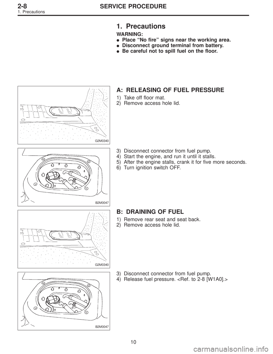
1. Precautions
WARNING:
�Place “No fire” signs near the working area.
�Disconnect ground terminal from battery.
�Be careful not to spill fuel on the floor.
G2M0340
A: RELEASING OF FUEL PRESSURE
1) Take off floor mat.
2) Remove access hole lid.
B2M0047
3) Disconnect connector from fuel pump.
4) Start the engine, and run it until it stalls.
5) After the engine stalls, crank it for five more seconds.
6) Turn ignition switch OFF.
G2M0340
B: DRAINING OF FUEL
1) Remove rear seat and seat back.
2) Remove access hole lid.
B2M0047
3) Disconnect connector from fuel pump.
4) Release fuel pressure.
10
2-8SERVICE PROCEDURE
1. Precautions
Page 597 of 3342
1) Set the vehicle on lift arms.
2) Open front hood fully and support with stay.
G2M0341
3) Release fuel pressure.
(1) Disconnect fuel tank connector.
(2) Start the engine, and run until it stalls.
(3) After the engine stalls, crank it for five seconds
more.
(4) Turn ignition switch to“OFF”.
G6M0095
4) Disconnect battery cables and remove battery from
vehicle.
B2M0015A
5) Drain coolant.
Set container under the vehicle, and remove drain cock
from radiator.
G2M0263
6) Remove cooling system.
(1) Disconnect radiator fan motor connector.
(2) Disconnect radiator outlet hose from thermostat
cover.
9
2-11SERVICE PROCEDURE
2. Engine
Page 734 of 3342

G3M0291
2. INHIBITOR SWITCH
The inhibitor switch allows the back-up lights to turn on
when the select lever is in the R range and the starter
motor to start when the lever is in the N or P range.
When driving condition or starter motor operation is
erroneous, first check the shift linkage for improper opera-
tion. If the shift linkage is functioning properly, check the
inhibitor switch.
(1) Disconnect cable end from select lever.
(2) Disconnect inhibitor switch side connector.
(3) Check continuity in inhibitor switch circuits with
select lever moved to each position.
CAUTION:
Also check that continuity in ignition circuit does not
exist when selector lever is in R, D, 3, 2 and 1 ranges.
NOTE:
If inhibitor switch is inoperative, check for poor contact of
connector on transmission side. (Plastic body type inhibi-
tor switch)
PinNo. 432187651211109
Lead color
B Y Br YG W BY R GW BY BW BW RW
Position
P��
��
R����
N����
D��
3��
2��
1��
Signal sent to AT control unit Ignition circuitBack-up light
circuit
B3H0016A
28
3-2SERVICE PROCEDURE
2. On-Car Service
Page 834 of 3342

G3M0291
2. INHIBITOR SWITCH
The inhibitor switch allows the back-up lights to turn on
when the select lever is in the R range and the starter
motor to start when the lever is in the N or P range.
When driving condition or starter motor operation is
erroneous, first check the shift linkage for improper opera-
tion. If the shift linkage is functioning properly, check the
inhibitor switch.
(1) Disconnect cable end from select lever.
(2) Disconnect inhibitor switch side connector.
(3) Check continuity in inhibitor switch circuits with
select lever moved to each position.
CAUTION:
Also check that continuity in ignition circuit does not
exist when selector lever is in R, D, 3, 2 and 1 ranges.
NOTE:
If inhibitor switch is inoperative, check for poor contact of
connector on transmission side. (Plastic body type inhibi-
tor switch)
PinNo. 432187651211109
Lead color
B Y Br YG W BY R GW BY BW BW RW
Position
P��
��
R����
N����
D��
3��
2��
1��
Signal sent to AT control unit Ignition circuitBack-up light
circuit
B3H0016A
28
3-2SERVICE PROCEDURE
2. On-Car Service
 Set the vehicle on lift arms.
2) Open front hood fully and support with stay.
G2M0341
3) Release fuel pressure.
(1) Disconnect fuel tank connector.
(2) Start the engine, and run until it stalls.
(3")