Page 463 of 3342
 Turn ignition switch to OFF.
2) Disconnect connectors from fuse and relay box, and
A/C relay holder.
3) Measure")
B2M0325A
2. CHECK HARNESS CONNECTOR BETWEEN FUSE
AND RELAY BOX, AND A/C RELAY HOLDER.
1) Turn ignition switch to OFF.
2) Disconnect connectors from fuse and relay box, and
A/C relay holder.
3) Measure resistance of harness connector between fuse
and relay box, and A/C relay holder.
Connector & terminal / Specified resistance:
(F40) No. 3—(F29) No. 2 / 10Ω, max.
B2M0428A
3. CHECK A/C RELAY HOLDER.
1) Disconnect connector from A/C relay holder.
2) Measure resistance between terminals of A/C relay
holder.
Connector & terminal / Specified resistance:
(F29) No. 2—(F28) No. 4 / 10Ω, max.
(F29) No. 2—(F30) No. 4 / 10Ω, max.
B2M0366A
4. CHECK HARNESS CONNECTOR BETWEEN A/C
RELAY HOLDER AND MAIN FAN MOTOR.
1) Disconnect connectors from A/C relay holder and main
fan motor.
2) Measure resistance of harness connector between A/C
relay holder and main fan motor.
Connector & terminal / Specified resistance:
(F28) No. 4—(F17) No. 2 / 10Ω, max.
(F30) No. 4—(F17) No. 3 / 10Ω, max.
B2M0367A
5. CHECK GROUND CIRCUIT OF MAIN FAN MOTOR.
Measure resistance between main fan motor connector
and body.
Connector & terminal / Specified resistance:
(F17) No. 1—Body / 10Ω, max.
B2M0368A
6. CHECK MAIN FAN MOTOR.
1) Disconnect connector from main fan motor.
2) Connect battery positive (+) terminal to terminals No. 2
and No. 3, and connect terminal No. 1 to ground. Ensure
that fan rotates.
23
2-5DIAGNOSTICS
2. Radiator Main Fan
Page 465 of 3342
 Turn ignition switch to OFF.
2) Disconnect connector from A/C relay holder.
3) Measure voltage between A/C relay holder connector
and body.
Conne")
B2M0369A
1. CHECK POWER SUPPLY TO MAIN FAN RELAY-1.
1) Turn ignition switch to OFF.
2) Disconnect connector from A/C relay holder.
3) Measure voltage between A/C relay holder connector
and body.
Connector & terminal / Specified voltage:
(F28) No. 2—Body / 10 V, or more
(F28) No. 1—Body / 1 V, max.
4) Turn ignition switch to ON.
5) Measure voltage between A/C relay holder connector
and body.
Connector & terminal / Specified voltage:
(F28) No. 1—Body / 10 V, or more
B2M0370A
2. CHECK MAIN FAN RELAY-1.
1) Turn ignition switch to OFF.
2) Remove main fan relay-1 from A/C relay holder.
3) Check continuity between terminals (indicated in table
below) when terminal (1) is connected to battery and ter-
minal (3) is grounded.
When current flows.Between terminals (2)
and (4)Continuity exists.
When current does not
flow.Between terminals (2)
and (4)Continuity does not
exist.
Between terminals (1)
and (3)Continuity exists.
B2M0371A
3. CHECK HARNESS CONNECTOR BETWEEN MAIN
FAN RELAY-1 AND MAIN FAN MOTOR.
1) Disconnect connectors from main fan relay-1 and main
fan motor.
2) Measure resistance of harness connector between
main fan relay-1 and main fan motor.
Connector & terminal / Specified resistance:
(F28) No. 4—(F17) No.2 / 10Ω, max.
25
2-5DIAGNOSTICS
2. Radiator Main Fan
Page 468 of 3342
![SUBARU LEGACY 1997 Service Repair Manual 1. CHECK OPERATION OF MAIN FAN MOTOR LO
MODE.
Check that radiator main fan rotates at LO speed under
each condition described under LO mode operation. <Ref.
to 2-5 [K2B0].>
B2M0374A
2. CHECK POWER SUP](/manual-img/17/57434/w960_57434-467.png "SUBARU LEGACY 1997 Service Repair Manual 1. CHECK OPERATION OF MAIN FAN MOTOR LO
MODE.
Check that radiator main fan rotates at LO speed under
each condition described under LO mode operation. <Ref.
to 2-5 [K2B0].>
B2M0374A
2. CHECK POWER SUP")
1. CHECK OPERATION OF MAIN FAN MOTOR LO
MODE.
Check that radiator main fan rotates at LO speed under
each condition described under LO mode operation.
to 2-5 [K2B0].>
B2M0374A
2. CHECK POWER SUPPLY TO MAIN FAN RELAY-2.
1) Turn ignition switch to OFF.
2) Disconnect connector from A/C relay holder.
3) Measure voltage between A/C relay holder connector
and body.
Connector & terminal / Specified voltage:
(F30) No. 2—Body / 10 V, or more
(F30) No. 1—Body / 1 V, max.
4) Turn ignition switch to ON.
5) Measure voltage between A/C relay holder connector
and body.
Connector & terminal / Specified voltage:
(F30) No. 1—Body / 10 V, or more
B2M0370A
3. CHECK MAIN FAN RELAY-2.
1) Turn ignition switch to OFF.
2) Remove main fan relay-2 from A/C relay holder.
3) Check continuity between terminals (indicated in table
below) when terminal (1) is connected to battery and ter-
minal (3) is grounded.
When current flows.Between terminals (2)
and (4)Continuity exists.
When current does not
flow.Between terminals (2)
and (4)Continuity does not
exist.
Between terminals (1)
and (3)Continuity exists.
28
2-5DIAGNOSTICS
2. Radiator Main Fan
Page 481 of 3342
B2M0340
(3) Remove bolts which secure power steering pipe
brackets to intake manifold.
NOTE:
Do not disconnect power steering hose.
B2M0334
(4) Remove bolts which install power steering pump to
bracket.
B2M0029
(5) Place power steering pump on the right side wheel
apron.
B6M0772
14) Disconnect spark plug cords from ignition coil.
B2M1239
15) Disconnect PCV hose from intake manifold.
12
2-7SERVICE PROCEDURE
4. Intake Manifold
Page 485 of 3342
B2M0347A
2) Disconnect connectors from throttle position sensor,
ignition coil, fuel injectors, idle air control solenoid valve,
purge control solenoid valve and EGR solenoid valve.
3) Remove engine harness from intake manifold.
�
1EGR solenoid valve
�
2Throttle position sensor
�
3Idle air control solenoid valve
�
4Purge control solenoid valve
�
5Harness band
H2M1247
4) Remove idle air control solenoid valve from intake
manifold.
B2M0157
5) Remove throttle body from intake manifold.
B2M0161B
6) Remove fuel pipes, etc. from intake manifold.
�
1Pressure regulator
�
2Fuel pipe ASSY
7) Remove EGR solenoid valve and purge control sole-
noid valve.
B2M0161B
C: ASSEMBLY
1) Install EGR solenoid valve and purge control solenoid
valve.
2) Assemble fuel pipes, etc. to intake manifold.
�
1Pressure regulator
�
2Fuel pipe ASSY
16
2-7SERVICE PROCEDURE
4. Intake Manifold
Page 486 of 3342
B2M0157
3) Assemble throttle body to intake manifold.
CAUTION:
Replace gasket with a new one.
Tightening torque:
22±2 N⋅m (2.2±0.2 kg-m, 15.9±1.4 ft-lb)
H2M1247
4) Install idle air control solenoid valve to intake manifold.
CAUTION:
Replace gasket with a new one.
Tightening torque:
6.4±0.5 N⋅m (0.65±0.05 kg-m, 4.7±0.4 ft-lb)
B2M0347A
5) Install engine harness onto intake manifold.
6) Connect connectors to throttle position sensor, ignition
coil, fuel injectors, idle air control solenoid valve, purge
control solenoid valve and EGR solenoid valve.
�
1EGR solenoid valve
�
2Throttle position sensor
�
3Idle air control solenoid valve
�
4Purge control solenoid valve
�
5Harness band
B2M0757A
7) Connect engine ground terminal to intake manifold.
B2M0159
D: INSTALLATION
1) Install intake manifold onto cylinder heads.
CAUTION:
Always use new gaskets.
Tightening torque:
25±2 N⋅m (2.5±0.2 kg-m, 18.1±1.4 ft-lb)
17
2-7SERVICE PROCEDURE
4. Intake Manifold
Page 489 of 3342
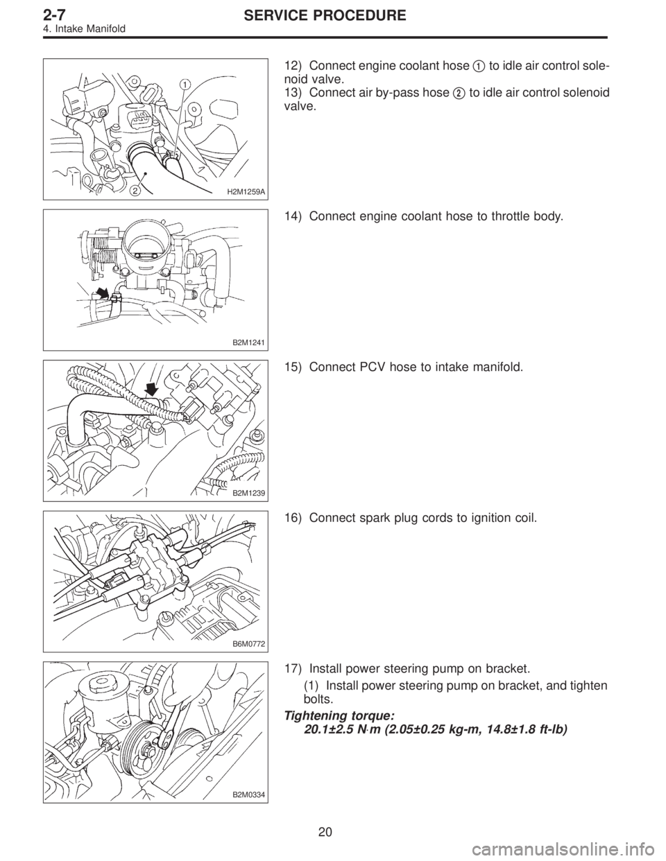
H2M1259A
12) Connect engine coolant hose�1to idle air control sole-
noid valve.
13) Connect air by-pass hose�
2to idle air control solenoid
valve.
B2M1241
14) Connect engine coolant hose to throttle body.
B2M1239
15) Connect PCV hose to intake manifold.
B6M0772
16) Connect spark plug cords to ignition coil.
B2M0334
17) Install power steering pump on bracket.
(1) Install power steering pump on bracket, and tighten
bolts.
Tightening torque:
20.1±2.5 N⋅m (2.05±0.25 kg-m, 14.8±1.8 ft-lb)
20
2-7SERVICE PROCEDURE
4. Intake Manifold
Page 499 of 3342
 Install rear oxygen sensor.
Tightening torque:
21±3 N⋅m (2.1±0.3 kg-m, 15.2±2.2 ft-lb)
3) Lower the vehicle.
4) Connect connector to rear oxygen sensor.
B2M0162
9. Throttle Position Se")
B2M0741
2) Install rear oxygen sensor.
Tightening torque:
21±3 N⋅m (2.1±0.3 kg-m, 15.2±2.2 ft-lb)
3) Lower the vehicle.
4) Connect connector to rear oxygen sensor.
B2M0162
9. Throttle Position Sensor
A: REMOVAL AND INSTALLATION
1) Disconnect connector from throttle position sensor.
2) Remove throttle position sensor holding screws, and
remove it.
3) Installation is in the reverse order of removal.
Tightening torque:
2.2±0.2 N⋅m (0.22±0.02 kg-m, 1.6±0.1 ft-lb)
CAUTION:
When installing throttle position sensor, adjust to the
specified data.
B2M0163
B: ADJUSTMENT
1) Turn ignition switch to OFF.
2) Loosen throttle position sensor holding screws.
G2M0415
3) When using voltage meter;
(1) Take out ECM.
(2) Turn ignition switch to ON.
(3) Adjust throttle position sensor so that signal voltage
to ECM may be in specification.
Connector & Terminal / Specified voltage
(B84) No. 24 — (B84) No. 25 / 0.45 — 0.55 V
[Fully closed.]
(4) Tighten throttle position sensor holding screws.
27
2-7SERVICE PROCEDURE
8. Rear Oxygen Sensor - 9. Throttle Position Sensor
 Remove bolts which secure power steering pipe
brackets to intake manifold.
NOTE:
Do not disconnect power steering hose.
B2M0334
(4) Remove bolts which install power steering pump to
bracke")
 Disconnect connectors from throttle position sensor,
ignition coil, fuel injectors, idle air control solenoid valve,
purge control solenoid valve and EGR solenoid valve.
3) Remove engine h")
 Assemble throttle body to intake manifold.
CAUTION:
Replace gasket with a new one.
Tightening torque:
22±2 N⋅m (2.2±0.2 kg-m, 15.9±1.4 ft-lb)
H2M1247
4) Install idle air control soleno")