Page 1694 of 3342
 Using TORX®BIT T40 (Tamper resistant type), remove
two TORX®bolts.
Discard the old TORX®bolts.
CAUTION:
Use new TORX
®bolts during re-assembly.
B: INSTALLATION
Installation is in revers")
B5M0105
6) Using TORX®BIT T40 (Tamper resistant type), remove
two TORX®bolts.
Discard the old TORX®bolts.
CAUTION:
Use new TORX
®bolts during re-assembly.
B: INSTALLATION
Installation is in reverse order of removal procedures.
CAUTION:
Be sure to fully secure all airbag system connectors
during re-assembly and confirm that all green double
lock mechanisms are engaged.
6. Combination Switch
A: REMOVAL
1) Turn ignition switch off.
2) Disconnect ground cable from battery and wait for at
least 20 seconds before starting work.
G5M0312
3) Remove lower cover. Disconnect
airbag connector (AB3) and (AB8) below steering column.
CAUTION:
Do not reconnect airbag connector at steering column
until combination switch is securely re-installed.
4) Disconnect combination switch connectors from body
harness connector.
H5M0662A
5) Set front wheels in straight ahead position. Using
TORX®BIT T30, remove two TORX®bolts.
16
5-5bSERVICE PROCEDURE
5. Airbag Control Module - 6. Combination Switch
Page 1697 of 3342

1. Engine Electrical
A: SPECIFICATIONS
1. EXCEPT 2200 cc MODEL
Item Designation
StarterType Reduction type
ModelMT
TN128000-8311AT
TN128000-8321
Manufacturer NIPPONDENSO TENNESSEE
Voltage and output 12 V — 1.0 kW 12 V — 1.4 kW
Direction of rotation Counterclockwise (when observed from pinion)
Number of pinion teeth 8 9
No-load
characteristicsVoltage 11 V
Current 90 A or less
Rotating
speed3,000 rpm or more 2,900 rpm or more
Load
characteristicsVoltage 8 V
Current 280 A or less 370 A or less
Torque 9.8 N⋅m (1.0 kg-m, 7.2 ft-lb) 13.7 N⋅m (1.4 kg-m, 10.1 ft-lb)
Rotating
speed900 rpm or more 880 rpm or more
Lock
characteristicsVoltage 5 V
Current 800 A or less 1,050 A or less
Torque 27.5 N⋅m (2.8 kg-m, 20.3 ft-lb) or more
GeneratorType Rotating-field three-phase type, Voltage regulator built-in type
Model LR185-701H
Manufacturer HITACHI AUTOMOTIVE PRODUCTS
Voltage and output 12 V — 85 A
Polarity on ground side Negative
Rotating direction Clockwise (when observed from pulley side)
Armature connection 3-phase Y-type
Output current1,500 rpm — 35 A or more
2,500 rpm — 62 A or more
5,000 rpm — 82 A or more
Regulated voltage 14.5
+0.3
�0.4V [20°C (68°F)]
Ignition
coilModel F-569-01R
Manufacturer Diamond
Primary coil resistance 0.69Ω±10%
Secondary coil resistance 21.0 kΩ±15%
Insulation resistance between
primary terminal and caseMore than 10 MΩ
Spark
plugType and manufacturerRC10YC4 .......... CHAMPION
Alternate
(BKR6E-11 .......... NGK
K20PR-U11 .......... NIPPONDENSO)
Thread size mm 14, P = 1.25
Spark gap mm (in) 1.0 — 1.1 (0.039 — 0.043)
2
6-1SPECIFICATIONS AND SERVICE DATA
1. Engine Electrical
Page 1698 of 3342

2. 2200 cc MODEL
Item Designation
StarterType Reduction type
ModelMT
TN128000-8311AT
TN128000-8321
Manufacturer NIPPONDENSO TENNESSEE
Voltage and output 12 V—1.0 kW 12 V—1.4 kW
Direction of rotation Counterclockwise (when observed from pinion)
Number of pinion teeth 8 9
No-load
characteristicsVoltage 11 V
Current 90 A or less
Rotating
speed3,000 rpm or more 2,900 rpm or more
Load
characteristicsVoltage 8 V
Current 280 A or less 370 A or less
Torque 9.8 N⋅m (1.0 kg-m, 7.2 ft-lb) 13.7 N⋅m (1.4 kg-m, 10.1 ft-lb)
Rotating
speed900 rpm or more 880 rpm or more
Lock
characteristicsVoltage 5 V
Current 800 A or less 1,050 A or less
Torque 27.5 N⋅m (2.8 kg-m, 20.3 ft-lb) or more
GeneratorType Rotating-field three-phase type, Voltage regulator built-in type
Model LR185-701H
Manufacturer HITACHI AUTOMOTIVE PRODUCTS
Voltage and output 12 V—85 A
Polarity on ground side Negative
Rotating direction Clockwise (when observed from pulley side)
Armature connection 3-phase Y-type
Output current1,500 rpm—35 A or more
2,500 rpm—62 A or more
5,000 rpm—82 A or more
Regulated voltage 14.5
+0.3
�0.4V [20°C (68°F)]
Ignition
coilModel FH0047-01R
Manufacturer DEMCO
Primary coil resistance 0.73Ω±10%
Secondary coil resistance 12.8 kΩ±15%
Insulation resistance between
primary terminal and caseMore than 10 MΩ
Spark
plugType and manufacturerRC10YC4 .......... CHAMPION
Alternate
(BKR6E-11 .......... NGK
K20PR-U11 .......... NIPPONDENSO)
Thread size mm 14, P = 1.25
Spark gap mm (in) 1.0—1.1 (0.039—0.043)
3
6-1SPECIFICATIONS AND SERVICE DATA
1. Engine Electrical
Page 1720 of 3342
 Carbon fouled
Dry fluffy carbon deposits on insulator and electrode are
mostly caused by slow speed driving in city, weak ignition,
too rich fuel mixture, dirty air cleaner, etc.
It is advi")
G6M0088
2) Carbon fouled
Dry fluffy carbon deposits on insulator and electrode are
mostly caused by slow speed driving in city, weak ignition,
too rich fuel mixture, dirty air cleaner, etc.
It is advisable to replace with plugs having hotter heat
range.
G6M0089
3) Oil fouled
Wet black deposits show excessive oil entrance into com-
bustion chamber through worn rings and pistons or exces-
sive clearance between valve guides and stems. If same
condition remains after repair, use a hotter plug.
G6M0090
4) Overheating
White or light gray insulator with black or gray brown spots
and bluish burnt electrodes indicate engine overheating.
Moreover, the appearance results from incorrect ignition
timing, loose spark plugs, wrong selection of fuel, hotter
range plug, etc. It is advisable to replace with plugs having
colder heat range.
G6M0091
C: CLEANING AND REGAPPING
Clean spark plugs in a sand blast type cleaner.
Avoid excessive blasting. Clean and remove carbon or
oxide deposits, but do not wear away porcelain.
If deposits are too stubborn, discard plugs.
After cleaning spark plugs, recondition firing surface of
electrodes with file. Then correct the spark plug gap using
a gap gauge.
Spark plug gap: L
1.0—1.1 mm (0.039—0.043 in)
D: REMOVAL AND INSTALLATION (2500 cc
EXCEPT OUTBACK MODEL)
CAUTION:
All spark plugs installed on an engine, must be of the
same heat range.
Spark plug:
NGK: PFR5B-11
24
6-1SERVICE PROCEDURE
3. Spark Plug
Page 1732 of 3342
 Disconnect battery ground cable.
2) Disconnect connector from ignition coil.
3) Remove ignition coil.
4) Installation is")
B6M0160
4. Ignition Coil
A: REMOVAL AND INSTALLATION
1. EXCEPT 2200 cc MODEL
1) Disconnect battery ground cable.
2) Disconnect connector from ignition coil.
3) Remove ignition coil.
4) Installation is in the reverse order of removal.
CAUTION:
Be sure to connect wires to their proper positions.
Failure to do so will damage unit.
B6M0772
2. 2200 cc MODEL
1) Disconnect battery ground cable.
2) Disconnect connector from ignition coil.
3) Disconnect spark plug cords from ignition coil.
4) Remove ignition coil.
5) Installation is in the reverse order of removal.
CAUTION:
Be sure to connect wires to their proper positions.
Failure to do so will damage unit.
B6M0774B
B6M0773B
B: INSPECTION
Using accurate tester, inspect the following items, and
replace if defective.
1) Primary resistance
2) Secondary coil resistance
CAUTION:
If the resistance is extremely low, this indicates the
presence of a short-circuit.
Specified resistance:
[Primary side]
Between terminal No. 1 and No. 2
Between terminal No. 2 and No. 3
0.73Ω±10%
[Secondary side]
Between�
1and�2
Between�3and�4
12.8 kΩ±15%
3) Insulation between primary terminal and case: 10 MΩ
or more.
36
6-1SERVICE PROCEDURE
4. Ignition Coil
Page 1736 of 3342
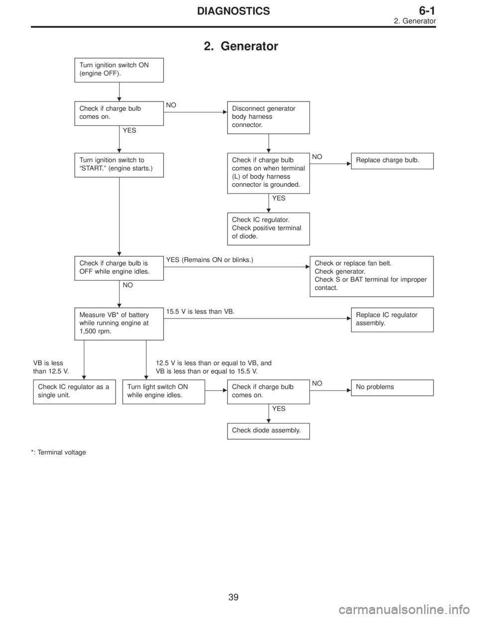
2. Generator
Turn ignition switch ON
(engine OFF).
Check if charge bulb
comes on.
YES
�NO
Disconnect generator
body harness
connector.
Turn ignition switch to
“START.”(engine starts.)Check if charge bulb
comes on when terminal
(L) of body harness
connector is grounded.
YES
�NO
Replace charge bulb.
Check IC regulator.
Check positive terminal
of diode.
Check if charge bulb is
OFF while engine idles.
NO
�YES (Remains ON or blinks.)
Check or replace fan belt.
Check generator.
Check S or BAT terminal for improper
contact.
Measure VB* of battery
while running engine at
1,500 rpm.�15.5 V is less than VB.
Replace IC regulator
assembly.
VB is less
than 12.5 V.12.5 V is less than or equal to VB, and
VB is less than or equal to 15.5 V.
Check IC regulator as a
single unit.
Turn light switch ON
while engine idles.�Check if charge bulb
comes on.
YES
�NO
No problems
Check diode assembly.
*: Terminal voltage
�
��
�
�
�
��
�
39
6-1DIAGNOSTICS
2. Generator
Page 1739 of 3342

1. Precaution
�Before disassembling or reassembling parts, always
disconnect battery ground cable. When repairing
radio, control modules, etc. which are provided with
memory functions, record memory contents before
disconnecting battery ground cable. Otherwise, these
contents are cancelled upon disconnection.
�Reassemble parts in reverse order of disassembly
procedure unless otherwise indicated.
�Adjust parts to specifications contained in this
manual if so designated.
�Connect connectors and hoses securely during
reassembly.
�After reassembly, ensure functional parts operate
smoothly.
CAUTION:
�Airbag system wiring harness is routed near the
electrical parts and switch.
�All Airbag system wiring harness and connectors
are colored yellow. Do not use electrical test equip-
ment on these circuit.
�Be careful not to damage Airbag system wiring har-
ness when servicing the ignition key cylinder.
G6M0102
2. Battery
A: REMOVAL AND INSTALLATION
1. BATTERY
1) Disconnect the positive (+) terminal after disconnecting
the negative (�) terminal of battery.
2) Remove flange nuts from battery rods and take off bat-
tery holder.
3) Remove battery.
Tightening torque:
3.4±1.0 N⋅m (0.35±0.1 kg-m, 2.5±0.7 ft-lb)
NOTE:
�Clean battery cable terminals and apply grease to retard
the formation of corrosion.
�Connect the positive (+) terminal of battery and then the
negative (�) terminal of the battery.
4
6-2SERVICE PROCEDURE
1. Precaution - 2. Battery
Page 1740 of 3342

1. Precaution
�Before disassembling or reassembling parts, always
disconnect battery ground cable. When repairing
radio, control modules, etc. which are provided with
memory functions, record memory contents before
disconnecting battery ground cable. Otherwise, these
contents are cancelled upon disconnection.
�Reassemble parts in reverse order of disassembly
procedure unless otherwise indicated.
�Adjust parts to specifications contained in this
manual if so designated.
�Connect connectors and hoses securely during
reassembly.
�After reassembly, ensure functional parts operate
smoothly.
CAUTION:
�Airbag system wiring harness is routed near the
electrical parts and switch.
�All Airbag system wiring harness and connectors
are colored yellow. Do not use electrical test equip-
ment on these circuit.
�Be careful not to damage Airbag system wiring har-
ness when servicing the ignition key cylinder.
G6M0102
2. Battery
A: REMOVAL AND INSTALLATION
1. BATTERY
1) Disconnect the positive (+) terminal after disconnecting
the negative (�) terminal of battery.
2) Remove flange nuts from battery rods and take off bat-
tery holder.
3) Remove battery.
Tightening torque:
3.4±1.0 N⋅m (0.35±0.1 kg-m, 2.5±0.7 ft-lb)
NOTE:
�Clean battery cable terminals and apply grease to retard
the formation of corrosion.
�Connect the positive (+) terminal of battery and then the
negative (�) terminal of the battery.
4
6-2SERVICE PROCEDURE
1. Precaution - 2. Battery