Page 1837 of 3342
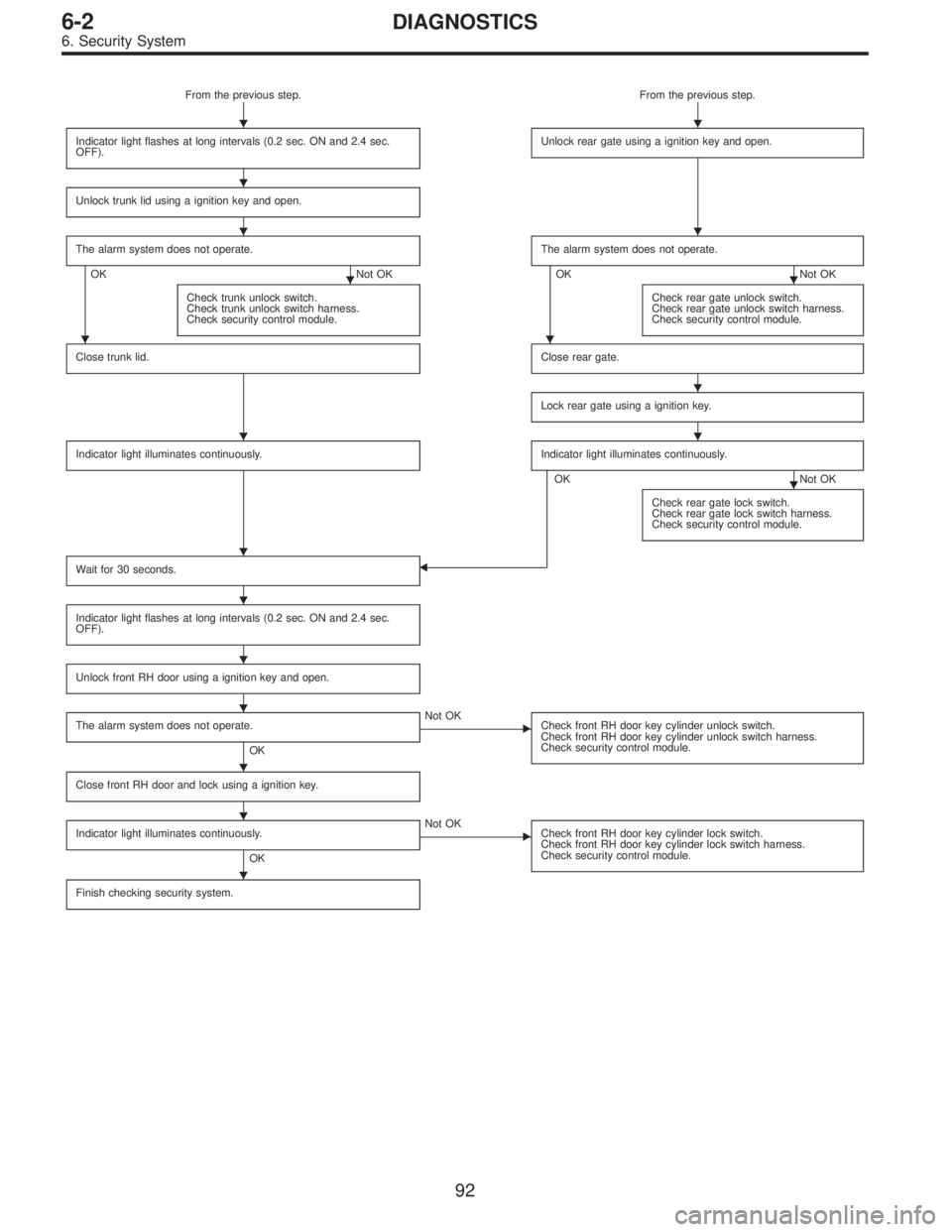
From the previous step. From the previous step.
Indicator light flashes at long intervals (0.2 sec. ON and 2.4 sec.
OFF).
Unlock rear gate using a ignition key and open.
Unlock trunk lid using a ignition key and open.
The alarm system does not operate.
OK Not OKThe alarm system does not operate.OK Not OK
Check trunk unlock switch.
Check trunk unlock switch harness.
Check security control module.
Check rear gate unlock switch.
Check rear gate unlock switch harness.
Check security control module.
Close trunk lid.Close rear gate.
Lock rear gate using a ignition key.
Indicator light illuminates continuously.Indicator light illuminates continuously.
OK Not OK
Check rear gate lock switch.
Check rear gate lock switch harness.
Check security control module.
Wait for 30 seconds.
Indicator light flashes at long intervals (0.2 sec. ON and 2.4 sec.
OFF).
Unlock front RH door using a ignition key and open.
The alarm system does not operate.
OK
� Not OK
Check front RH door key cylinder unlock switch.
Check front RH door key cylinder unlock switch harness.
Check security control module.
Close front RH door and lock using a ignition key.
Indicator light illuminates continuously.
OK
� Not OK
Check front RH door key cylinder lock switch.
Check front RH door key cylinder lock switch harness.
Check security control module.
Finish checking security system.
�
��
�
��
��
��
�
��
�
�
�
�
�
�
�
�
92
6-2DIAGNOSTICS
6. Security System
Page 1838 of 3342
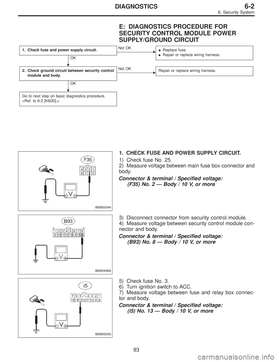
E: DIAGNOSTICS PROCEDURE FOR
SECURITY CONTROL MODULE POWER
SUPPLY/GROUND CIRCUIT
1. Check fuse and power supply circuit.
OK
�Not OK
�Replace fuse.
�Repair or replace wiring harness.
2. Check ground circuit between security control
module and body.
OK
�Not OK
Repair or replace wiring harness.
Go to next step on basic diagnostics procedure.
B6M0504A
1. CHECK FUSE AND POWER SUPPLY CIRCUIT.
1) Check fuse No. 25.
2) Measure voltage between main fuse box connector and
body.
Connector & terminal / Specified voltage:
(F35) No. 2—Body / 10 V, or more
B6M0448A
3) Disconnect connector from security control module.
4) Measure voltage between security control module con-
nector and body.
Connector & terminal / Specified voltage:
(B93) No. 8—Body / 10 V, or more
B6M0505A
5) Check fuse No. 3.
6) Turn ignition switch to ACC.
7) Measure voltage between fuse and relay box connec-
tor and body.
Connector & terminal / Specified voltage:
(i5) No. 13—Body / 10 V, or more
�
�
93
6-2DIAGNOSTICS
6. Security System
Page 1839 of 3342
B6M0452A
8) Disconnect connector from security control module.
9) Measure voltage between security control module con-
nector and body.
Connector & terminal / Specified voltage:
(B93) No. 6—Body / 10 V, or more
B6M0497A
2. CHECK GROUND CIRCUIT BETWEEN SECURITY
CONTROL MODULE AND BODY.
1) Turn ignition switch to OFF.
2) Disconnect connector of security control module.
3) Measure resistance of harness connector between
security control module and body.
Connector & terminal / Specified resistance:
(B93) No. 9—Body / 10Ω, max.
94
6-2DIAGNOSTICS
6. Security System
Page 1844 of 3342
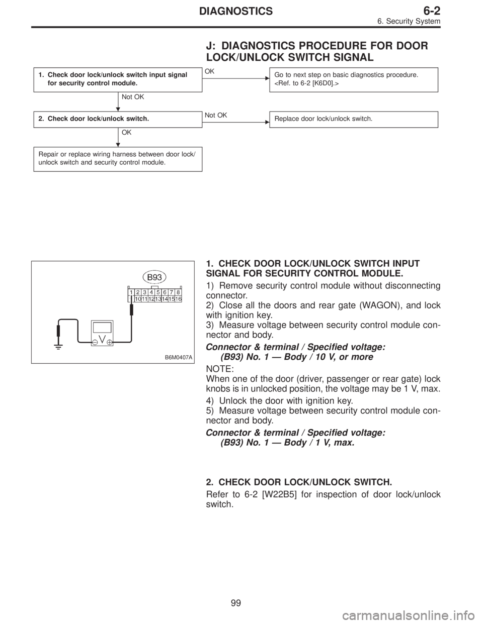
J: DIAGNOSTICS PROCEDURE FOR DOOR
LOCK/UNLOCK SWITCH SIGNAL
1. Check door lock/unlock switch input signal
for security control module.
Not OK
�OK
Go to next step on basic diagnostics procedure.
2. Check door lock/unlock switch.
OK
�Not OK
Replace door lock/unlock switch.
Repair or replace wiring harness between door lock/
unlock switch and security control module.
B6M0407A
1. CHECK DOOR LOCK/UNLOCK SWITCH INPUT
SIGNAL FOR SECURITY CONTROL MODULE.
1) Remove security control module without disconnecting
connector.
2) Close all the doors and rear gate (WAGON), and lock
with ignition key.
3) Measure voltage between security control module con-
nector and body.
Connector & terminal / Specified voltage:
(B93) No. 1—Body / 10 V, or more
NOTE:
When one of the door (driver, passenger or rear gate) lock
knobs is in unlocked position, the voltage may be 1 V, max.
4) Unlock the door with ignition key.
5) Measure voltage between security control module con-
nector and body.
Connector & terminal / Specified voltage:
(B93) No. 1—Body/1V,max.
2. CHECK DOOR LOCK/UNLOCK SWITCH.
Refer to 6-2 [W22B5] for inspection of door lock/unlock
switch.
�
�
99
6-2DIAGNOSTICS
6. Security System
Page 1847 of 3342
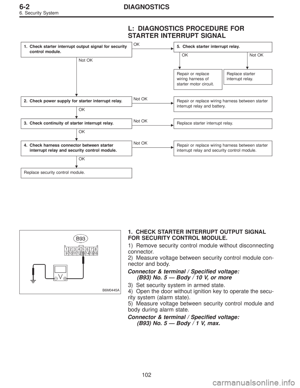
L: DIAGNOSTICS PROCEDURE FOR
STARTER INTERRUPT SIGNAL
1. Check starter interrupt output signal for security
control module.
Not OK
�OK
5. Check starter interrupt relay.
OK Not OK
Repair or replace
wiring harness of
starter motor circuit.
Replace starter
interrupt relay.
2. Check power supply for starter interrupt relay.
OK
�Not OK
Repair or replace wiring harness between starter
interrupt relay and battery.
3. Check continuity of starter interrupt relay.
OK
�Not OK
Replace starter interrupt relay.
4. Check harness connector between starter
interrupt relay and security control module.
OK
�Not OK
Repair or replace wiring harness between starter
interrupt relay and security control module.
Replace security control module.
B6M0445A
1. CHECK STARTER INTERRUPT OUTPUT SIGNAL
FOR SECURITY CONTROL MODULE.
1) Remove security control module without disconnecting
connector.
2) Measure voltage between security control module con-
nector and body.
Connector & terminal / Specified voltage:
(B93) No. 5—Body / 10 V, or more
3) Set security system in armed state.
4) Open the door without ignition key to operate the secu-
rity system (alarm state).
5) Measure voltage between security control module and
body during alarm state.
Connector & terminal / Specified voltage:
(B93) No. 5—Body/1V,max.
��
�
�
�
�
102
6-2DIAGNOSTICS
6. Security System
Page 1849 of 3342
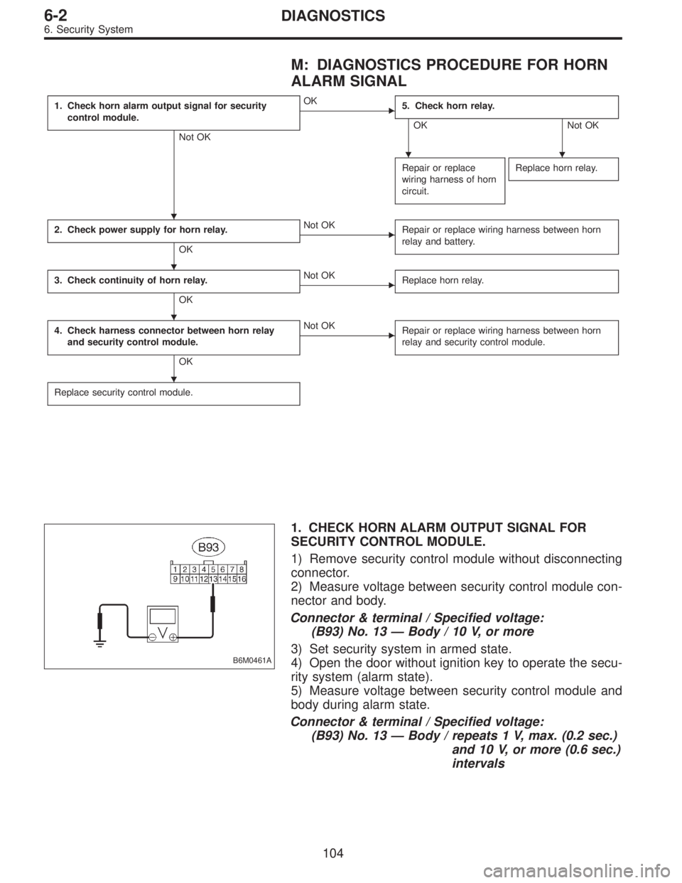
M: DIAGNOSTICS PROCEDURE FOR HORN
ALARM SIGNAL
1. Check horn alarm output signal for security
control module.
Not OK
�OK
5. Check horn relay.
OK Not OK
Repair or replace
wiring harness of horn
circuit.
Replace horn relay.
2. Check power supply for horn relay.
OK
�Not OK
Repair or replace wiring harness between horn
relay and battery.
3. Check continuity of horn relay.
OK
�Not OK
Replace horn relay.
4. Check harness connector between horn relay
and security control module.
OK
�Not OK
Repair or replace wiring harness between horn
relay and security control module.
Replace security control module.
B6M0461A
1. CHECK HORN ALARM OUTPUT SIGNAL FOR
SECURITY CONTROL MODULE.
1) Remove security control module without disconnecting
connector.
2) Measure voltage between security control module con-
nector and body.
Connector & terminal / Specified voltage:
(B93) No. 13—Body / 10 V, or more
3) Set security system in armed state.
4) Open the door without ignition key to operate the secu-
rity system (alarm state).
5) Measure voltage between security control module and
body during alarm state.
Connector & terminal / Specified voltage:
(B93) No. 13—Body / repeats 1 V, max. (0.2 sec.)
and 10 V, or more (0.6 sec.)
intervals
��
�
�
�
�
104
6-2DIAGNOSTICS
6. Security System
Page 1851 of 3342
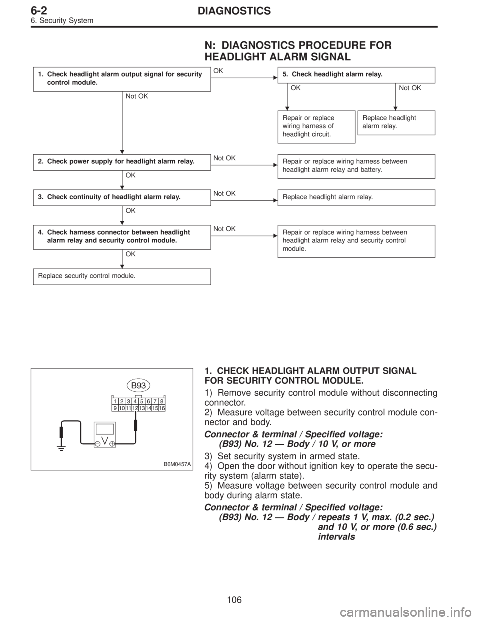
N: DIAGNOSTICS PROCEDURE FOR
HEADLIGHT ALARM SIGNAL
1. Check headlight alarm output signal for security
control module.
Not OK
�OK
5. Check headlight alarm relay.
OK Not OK
Repair or replace
wiring harness of
headlight circuit.
Replace headlight
alarm relay.
2. Check power supply for headlight alarm relay.
OK
�Not OK
Repair or replace wiring harness between
headlight alarm relay and battery.
3. Check continuity of headlight alarm relay.
OK
�Not OK
Replace headlight alarm relay.
4. Check harness connector between headlight
alarm relay and security control module.
OK
�Not OK
Repair or replace wiring harness between
headlight alarm relay and security control
module.
Replace security control module.
B6M0457A
1. CHECK HEADLIGHT ALARM OUTPUT SIGNAL
FOR SECURITY CONTROL MODULE.
1) Remove security control module without disconnecting
connector.
2) Measure voltage between security control module con-
nector and body.
Connector & terminal / Specified voltage:
(B93) No. 12—Body / 10 V, or more
3) Set security system in armed state.
4) Open the door without ignition key to operate the secu-
rity system (alarm state).
5) Measure voltage between security control module and
body during alarm state.
Connector & terminal / Specified voltage:
(B93) No. 12—Body / repeats 1 V, max. (0.2 sec.)
and 10 V, or more (0.6 sec.)
intervals
��
�
�
�
�
106
6-2DIAGNOSTICS
6. Security System
Page 1856 of 3342
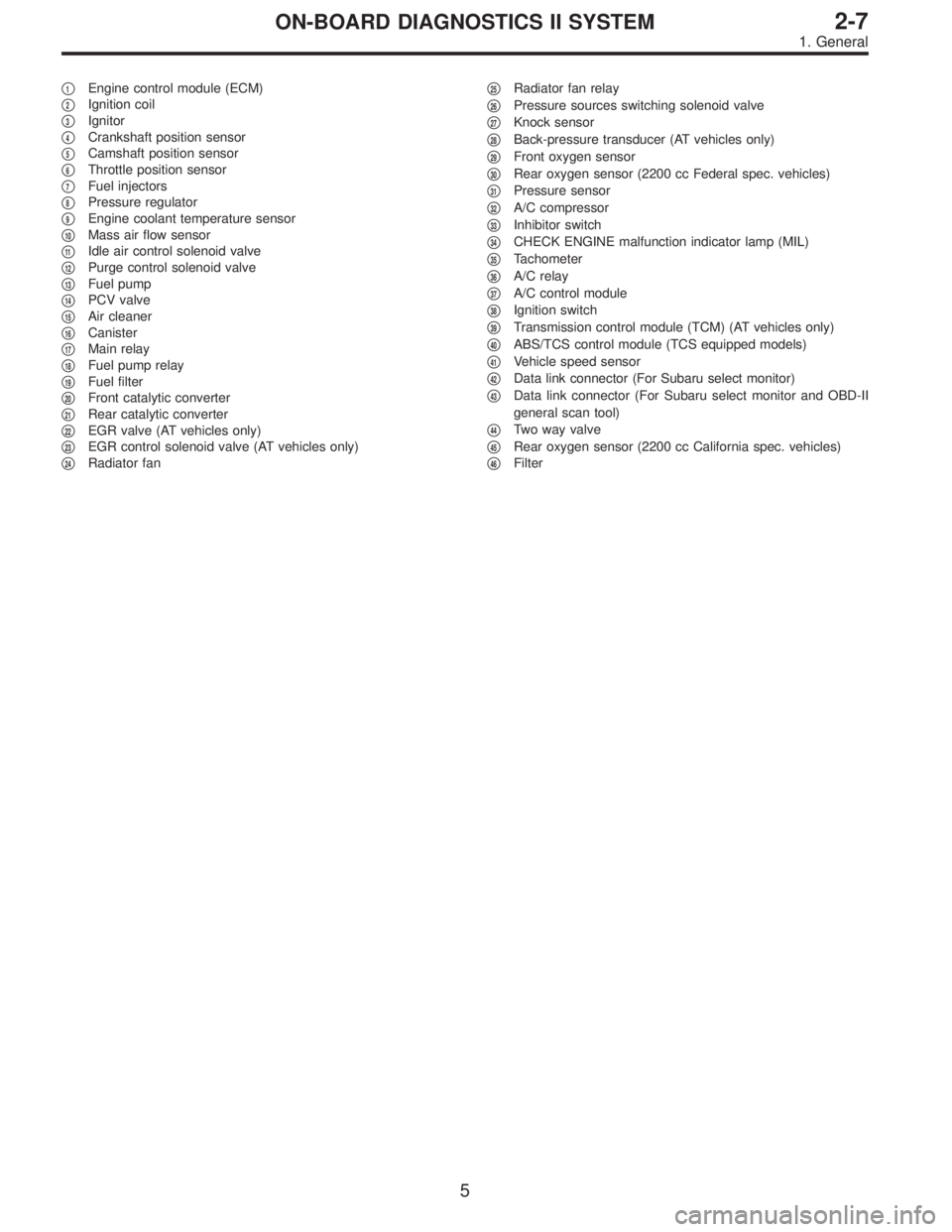
�1Engine control module (ECM)
�
2Ignition coil
�
3Ignitor
�
4Crankshaft position sensor
�
5Camshaft position sensor
�
6Throttle position sensor
�
7Fuel injectors
�
8Pressure regulator
�
9Engine coolant temperature sensor
�
10Mass air flow sensor
�
11Idle air control solenoid valve
�
12Purge control solenoid valve
�
13Fuel pump
�
14PCV valve
�
15Air cleaner
�
16Canister
�
17Main relay
�
18Fuel pump relay
�
19Fuel filter
�
20Front catalytic converter
�
21Rear catalytic converter
�
22EGR valve (AT vehicles only)
�
23EGR control solenoid valve (AT vehicles only)
�
24Radiator fan�
25Radiator fan relay
�
26Pressure sources switching solenoid valve
�
27Knock sensor
�
28Back-pressure transducer (AT vehicles only)
�
29Front oxygen sensor
�
30Rear oxygen sensor (2200 cc Federal spec. vehicles)
�
31Pressure sensor
�
32A/C compressor
�
33Inhibitor switch
�
34CHECK ENGINE malfunction indicator lamp (MIL)
�
35Tachometer
�
36A/C relay
�
37A/C control module
�
38Ignition switch
�
39Transmission control module (TCM) (AT vehicles only)
�
40ABS/TCS control module (TCS equipped models)
�
41Vehicle speed sensor
�
42Data link connector (For Subaru select monitor)
�
43Data link connector (For Subaru select monitor and OBD-II
general scan tool)
�
44Two way valve
�
45Rear oxygen sensor (2200 cc California spec. vehicles)
�
46Filter
5
2-7ON-BOARD DIAGNOSTICS II SYSTEM
1. General