Page 1895 of 3342
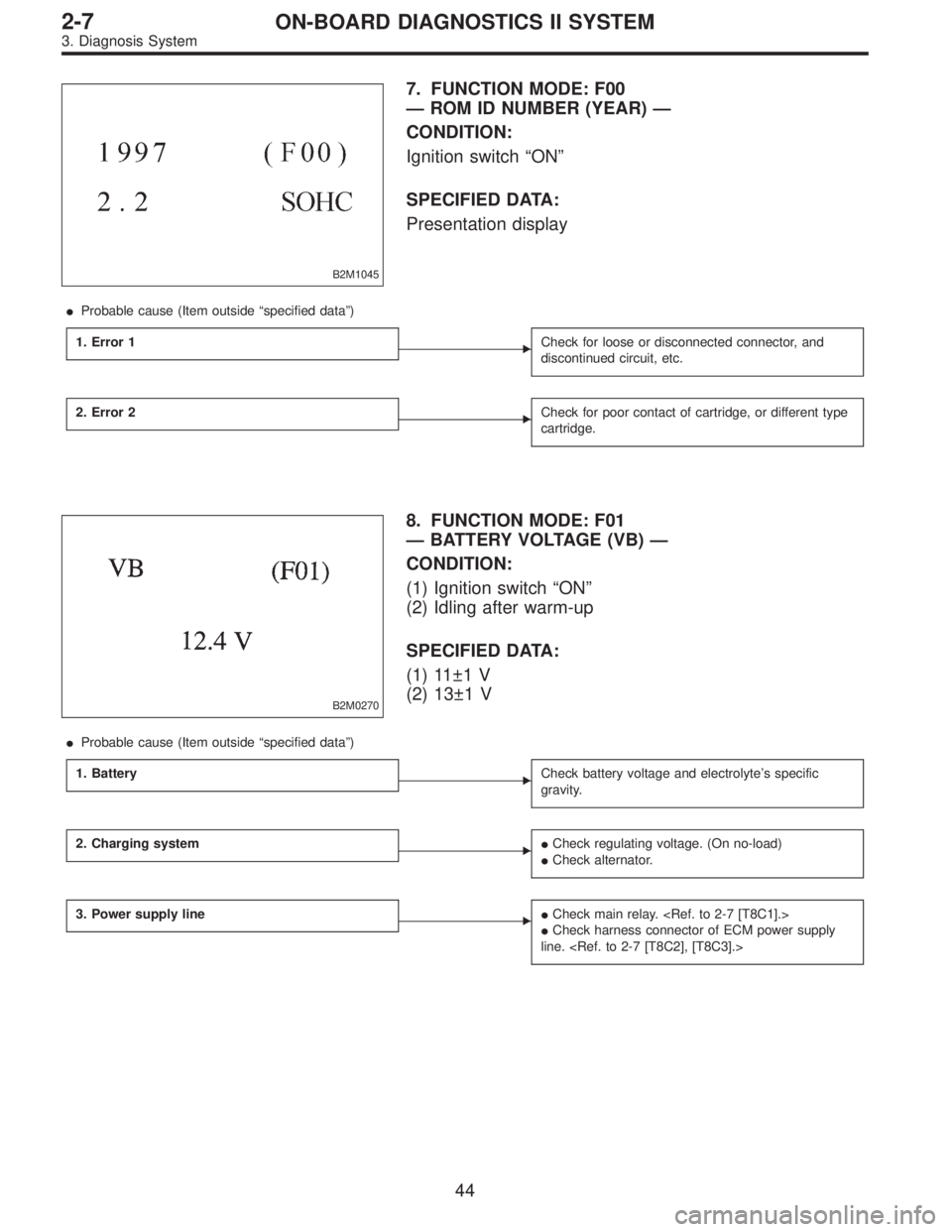
B2M1045
7. FUNCTION MODE: F00
— ROM ID NUMBER (YEAR) —
CONDITION:
Ignition switch“ON”
SPECIFIED DATA:
Presentation display
�Probable cause (Item outside“specified data”)
1. Error 1
�Check for loose or disconnected connector, and
discontinued circuit, etc.
2. Error 2�Check for poor contact of cartridge, or different type
cartridge.
B2M0270
8. FUNCTION MODE: F01
— BATTERY VOLTAGE (VB) —
CONDITION:
(1) Ignition switch“ON”
(2) Idling after warm-up
SPECIFIED DATA:
(1) 11±1 V
(2) 13±1 V
�Probable cause (Item outside“specified data”)
1. Battery
�Check battery voltage and electrolyte’s specific
gravity.
2. Charging system��Check regulating voltage. (On no-load)
�Check alternator.
3. Power supply line��Check main relay.
�Check harness connector of ECM power supply
line.
44
2-7ON-BOARD DIAGNOSTICS II SYSTEM
3. Diagnosis System
Page 1896 of 3342
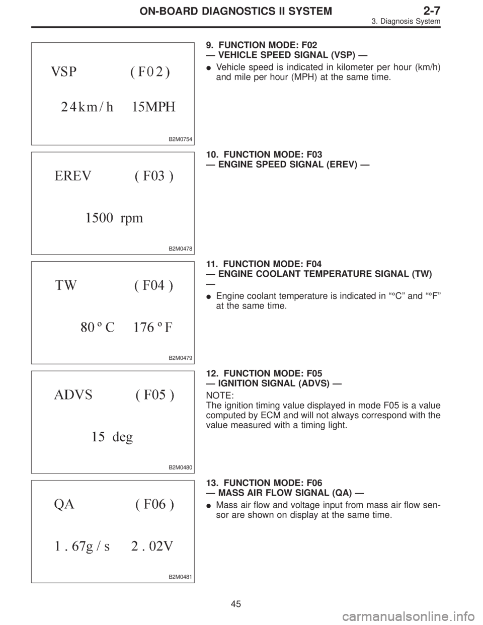
B2M0754
9. FUNCTION MODE: F02
—VEHICLE SPEED SIGNAL (VSP)—
�Vehicle speed is indicated in kilometer per hour (km/h)
and mile per hour (MPH) at the same time.
B2M0478
10. FUNCTION MODE: F03
—ENGINE SPEED SIGNAL (EREV)—
B2M0479
11. FUNCTION MODE: F04
—ENGINE COOLANT TEMPERATURE SIGNAL (TW)
—
�Engine coolant temperature is indicated in“°C”and“°F”
at the same time.
B2M0480
12. FUNCTION MODE: F05
—IGNITION SIGNAL (ADVS)—
NOTE:
The ignition timing value displayed in mode F05 is a value
computed by ECM and will not always correspond with the
value measured with a timing light.
B2M0481
13. FUNCTION MODE: F06
—MASS AIR FLOW SIGNAL (QA)—
�Mass air flow and voltage input from mass air flow sen-
sor are shown on display at the same time.
45
2-7ON-BOARD DIAGNOSTICS II SYSTEM
3. Diagnosis System
Page 1898 of 3342
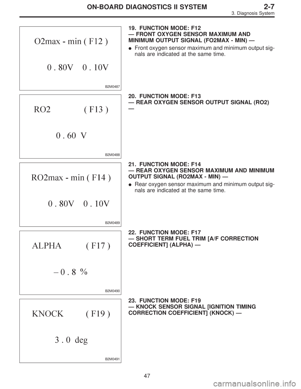
B2M0487
19. FUNCTION MODE: F12
—FRONT OXYGEN SENSOR MAXIMUM AND
MINIMUM OUTPUT SIGNAL (FO2MAX - MIN)—
�Front oxygen sensor maximum and minimum output sig-
nals are indicated at the same time.
B2M0488
20. FUNCTION MODE: F13
—REAR OXYGEN SENSOR OUTPUT SIGNAL (RO2)
—
B2M0489
21. FUNCTION MODE: F14
—REAR OXYGEN SENSOR MAXIMUM AND MINIMUM
OUTPUT SIGNAL (RO2MAX - MIN)—
�Rear oxygen sensor maximum and minimum output sig-
nals are indicated at the same time.
B2M0490
22. FUNCTION MODE: F17
—SHORT TERM FUEL TRIM [A/F CORRECTION
COEFFICIENT] (ALPHA)—
B2M0491
23. FUNCTION MODE: F19
—KNOCK SENSOR SIGNAL [IGNITION TIMING
CORRECTION COEFFICIENT] (KNOCK)—
47
2-7ON-BOARD DIAGNOSTICS II SYSTEM
3. Diagnosis System
Page 1903 of 3342

40. FA MODE FOR ENGINE
Function
modeLED No. Contents Display LED“ON”requirements
FA 03 Neutral switch NT When neutral position signal is entered.
7 Test mode connector UD When test mode connector is connected.
8 AT/MT identification signal AT When AT identification signal is entered.
9 Ignition switch IG When ignition switch is turned ON.
FA 11 Radiator fan relay 2 R2 When radiator fan relay 2 is in function.
2 Knock signal KS When knock signal is entered.
3 Purge control solenoid valve CN When purge control solenoid valve is in function.
4 Fuel pump relay FP When fuel pump relay is in function.
6 Radiator fan relay 1 R1 When radiator fan relay 1 is in function.
7 Air conditioner relay AR When air conditioner relay is in function.
8 Air conditioner switch AC When air conditioner switch is turned ON.
FA 22 AEC signal EC When AEC signal is entered.
3 EAM signal AM When EAM signal is gone out.
4 AEB signal EB When AEB signal is entered.
6 AET signal ET When AET signal is entered.
7 Engine torque control signal TR When engine torque control signal is entered.
FA3 7 Pressure sources switching solenoid valve BRWhen pressure sources switching solenoid valve
is in function.
FA 41 Catalyst CA When diagnosis of catalyzer is finished.
2 EGR system E1 When diagnosis of EGR system is finished.
3 California spec. vehicle identification signal FCWhen Federal spec. vehicle identification signal is
entered.
8 Rear oxygen sensor signal OR When rear oxygen sensor mixture ratio is rich.
9 Front oxygen sensor signal O2 When front oxygen sensor mixture ratio is rich.
FA 56 Vent control solenoid valve AL When vent control solenoid valve is in function.
7 EGR solenoid valve ER When EGR solenoid valve is in function.
8 Pressure control solenoid valve PCWhen pressure control solenoid valve is in
function.
52
2-7ON-BOARD DIAGNOSTICS II SYSTEM
3. Diagnosis System
Page 1904 of 3342

LED No. Signal name Display
1——
2——
3 Neutral switch NT
4——
5——
6——
7 Test mode connector UD
8 Identification of AT model AT
9 Ignition switch IG
0——
——NT——
—UD AT IG—
1
2345
67890
41. FUNCTION MODE: FA0
—ON↔OFF SIGNAL—
Requirement for LED“ON”.
LED No. 3�On MT model, gear position is in neutral.
�On AT model, shift position is in“P”or“N”.
LED No. 7 Test mode connector is connected.
LED No. 8 Vehicle is AT model.
LED No. 9 Ignition switch is turned ON.
LED No. Signal name Display
1 Radiator fan relay 2 R2
2 Knock signal KS
3Purge control solenoid
valveCN
4 Fuel pump relay FP
5——
6 Radiator fan relay 1 R1
7 A/C relay AR
8 A/C switch AC
9——
0——
R2 KS CN FP—
R1 AR AC——
1
2345
67890
42. FUNCTION MODE: FA1
—ON↔OFF SIGNAL—
Requirement for LED“ON”.
LED No. 1 Radiator fan relay 2 is turned ON.
LED No. 2 Engine is knocking.
LED No. 3 Purge control solenoid valve is in function.
LED No. 4 Fuel pump relay is turned ON.
LED No. 6 Radiator fan relay 1 is turned ON.
LED No. 7 A/C relay is turned ON.
LED No. 8 A/C switch is turned ON.
NOTE:
�When LED No. 1, 3, 4, 6 and 7 blinks with the test mode
connector connected and the ignition switch turned to ON,
the corresponding part is functioning properly.
�When LED No. 4 illuminates for only 2 seconds after the
ignition switch is turned to ON, (and then goes out), the
corresponding part is functioning properly.
�LED No. 3 is applicable only to the models not equipped
with enhanced evaporative emission control system.
53
2-7ON-BOARD DIAGNOSTICS II SYSTEM
3. Diagnosis System
Page 1905 of 3342

LED No. Signal name Display
1——
2 AEC signal EC
3 EAM signal AM
4 AEB signal EB
5——
6 AET signal ET
7Engine torque control
signalTR
8——
9——
0——
—EC AM EB—
ET TR———
1
2345
67890
43. FUNCTION MODE: FA2
—ON↔OFF SIGNAL—
Requirement for LED“ON”.
LED No. 2 ECM entered the AEC signal emitted from
TCS C/M.
LED No. 3 EAM signal goes out.
LED No. 4 ECM entered the AEB signal emitted from
TCS C/M.
LED No. 6 ECM entered the AET signal emitted from
TCS C/M.
LED No. 7 ECM entered the torque control signal emit-
ted from TCM.
LED No. Signal name Display
1——
2——
3——
4——
5——
6——
7Pressure sources switching
solenoid valveBR
8——
9——
0——
—————
—BR———
1
2345
67890
44. FUNCTION MODE: FA3
—ON↔OFF SIGNAL—
Requirement for LED“ON”.
LED No. 7 Pressure sources switching solenoid valve is
in function.
NOTE:
When LED No. 7 blinks with the test mode connector con-
nected and the ignition switch turned to ON, the corre-
sponding part is functioning properly.
54
2-7ON-BOARD DIAGNOSTICS II SYSTEM
3. Diagnosis System
Page 1906 of 3342

LED No. Signal name Display
1 Catalyst CA
2 EGR system E1
3California model
identification signalFC
4——
5——
6——
7——
8 Rear oxygen sensor signal OR
9 Front oxygen sensor signal O2
0——
CA E1 FC——
——OR O2—
1
2345
67890
45. FUNCTION MODE: FA4
—ON↔OFF SIGNAL—
Requirement for LED“ON”.
LED No. 1 Diagnosis of catalyzer is finished.
LED No. 2 Diagnosis of EGR system is finished.
LED No. 3 Vehicle is Federal specifications.
LED No. 8 Rear oxygen sensor mixture ratio is rich.
LED No. 9 Front oxygen sensor mixture ratio is rich.
LED No. Signal name Display
1——
2——
3——
4——
5——
6 Vent control solenoid valve AL
7 EGR solenoid valve ER
8Pressure control solenoid
valvePC
9——
0——
—————
AL ER PC——
1
2345
67890
46. FUNCTION MODE: FA5
—ON↔OFF SIGNAL—
Requirement for LED“ON”.
LED No. 6 Vent control solenoid valve is in function.
LED No. 7 EGR solenoid valve is in function.
LED No. 8 Pressure control solenoid valve is in func-
tion.
NOTE:
When LED No. 6, 7 and 8 blinks with the test mode con-
nector connected and the ignition switch turned to ON, the
corresponding part is functioning properly.
55
2-7ON-BOARD DIAGNOSTICS II SYSTEM
3. Diagnosis System
Page 1910 of 3342
B2M1046
52. FUNCTION MODE: F00
—MODE DISPLAY—
SPECIFIED DATA:
Data at the left should be indicated.
Probable cause (if outside“specified data”)
1. Communication failure
(No communication method can be confirmed
with power ON.)
�(1)Check loose or poor connectors, or
shortcircuit.
(2) Check type of cartridge.
2. Vehicle types cannot be identified (due to
communication failure).�Check improper cartridge.
Replace with proper one.
OBD0673
53. FUNCTION MODE: F01
—BATTERY VOLTAGE (VB)—
CONDITION:
(1) Ignition switch ON
(2) Engine idling after warm-up
SPECIFIED DATA:
(1) 12±1 V
(2) 13±1 V
1. Battery�Check battery voltage and specific gravity of
electrolyte.
2. Charging system�(1)Measure regulating voltage under no loads.
(2) Check generator (as a single unit).
59
2-7ON-BOARD DIAGNOSTICS II SYSTEM
3. Diagnosis System

1. Communication failure
(No communication metho")