Page 1858 of 3342

�
2Ignition coil
�
3Ignitor
�
4Crankshaft position sensor
�
5Camshaft position sensor
�
6Throttle position sensor
�
7Fuel injectors
�
8Pressure regulator
�
9Engine coolan")
�1Engine control module (ECM)
�
2Ignition coil
�
3Ignitor
�
4Crankshaft position sensor
�
5Camshaft position sensor
�
6Throttle position sensor
�
7Fuel injectors
�
8Pressure regulator
�
9Engine coolant temperature sensor
�
10Mass air flow sensor
�
11Idle air control solenoid valve
�
12Purge control solenoid valve
�
13Fuel pump
�
14PCV valve
�
15Air cleaner
�
16Canister
�
17Main relay
�
18Fuel pump relay
�
19Fuel filter
�
20Front catalytic converter
�
21Rear catalytic converter
�
22EGR valve (AT vehicles only)
�
23EGR control solenoid valve (AT vehicles only)
�
24Radiator fan
�
25Radiator fan relay
�
26Pressure sources switching solenoid valve�
27Front oxygen sensor
�
28Rear oxygen sensor (2200 cc Federal spec. vehicles)
�
29Pressure sensor
�
30A/C compressor (With A/C models)
�
31Inhibitor switch
�
32CHECK ENGINE malfunction indicator lamp (MIL)
�
33Tachometer
�
34A/C relay (With A/C models)
�
35A/C control module (With A/C models)
�
36Ignition switch
�
37Transmission control module (TCM)
�
38Vehicle speed sensor
�
39Data link connector (For Subaru select monitor)
�
40Data link connector (For Subaru select monitor and OBD-II
general scan tool)
�
41Rear oxygen sensor (2200 cc California spec. vehicles)
�
42Knock sensor
�
43Back-pressure transducer (AT vehicles only)
�
44Filter
�
45Fuel tank pressure sensor
�
46Pressure control solenoid valve
�
47Fuel temperature sensor
�
48Fuel level sensor
�
49Vent control solenoid valve
�
50Air filter
7
2-7ON-BOARD DIAGNOSTICS II SYSTEM
1. General
Page 1860 of 3342

�
2Ignition coil
�
3Ignitor
�
4Crankshaft position sensor
�
5Camshaft position sensor
�
6Throttle position sensor
�
7Fuel injectors
�
8Pressure regulator
�
9Engine coolan")
�1Engine control module (ECM)
�
2Ignition coil
�
3Ignitor
�
4Crankshaft position sensor
�
5Camshaft position sensor
�
6Throttle position sensor
�
7Fuel injectors
�
8Pressure regulator
�
9Engine coolant temperature sensor
�
10Mass air flow sensor
�
11Idle air control solenoid valve
�
12Purge control solenoid valve
�
13Fuel pump
�
14PCV valve
�
15Air cleaner
�
16Canister
�
17Main relay
�
18Fuel pump relay
�
19Fuel filter
�
20Front catalytic converter
�
21Rear catalytic converter
�
22EGR valve�
23EGR control solenoid valve
�
24Radiator fan
�
25Radiator fan relay
�
26Pressure sources switching solenoid valve
�
27Knock sensor
�
28Back-pressure transducer
�
29Front oxygen sensor
�
30Rear oxygen sensor
�
31Pressure sensor
�
32A/C compressor
�
33Inhibitor switch
�
34CHECK ENGINE malfunction indicator lamp (MIL)
�
35Tachometer
�
36A/C relay
�
37A/C control module
�
38Ignition switch
�
39Transmission control module (TCM)
�
40Vehicle speed sensor
�
41Data link connector (Subaru select monitor)
�
42Data link connector (OBD-II general scan tool)
�
43Two way valve
�
44Filter
9
2-7ON-BOARD DIAGNOSTICS II SYSTEM
1. General
Page 1871 of 3342
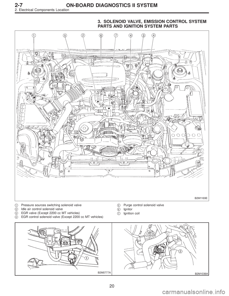
3. SOLENOID VALVE, EMISSION CONTROL SYSTEM
PARTS AND IGNITION SYSTEM PARTS
B2M1169E
�1Pressure sources switching solenoid valve
�
2Idle air control solenoid valve
�
3EGR valve (Except 2200 cc MT vehicles)
�
4EGR control solenoid valve (Except 2200 cc MT vehicles)�
5Purge control solenoid valve
�
6Ignitor
�
7Ignition coil
B2M0777AB2M1036A
20
2-7ON-BOARD DIAGNOSTICS II SYSTEM
2. Electrical Components Location
Page 1882 of 3342
B2M0470C
3. Diagnosis System
A: CHECK ENGINE MALFUNCTION
INDICATOR LAMP (MIL)
1. ACTIVATION OF CHECK ENGINE MALFUNCTION
INDICATOR LAMP (MIL)
1) When ignition switch is turned to ON (engine off), the
CHECK ENGINE malfunction indicator lamp (MIL) in the
combination meter illuminates.
NOTE:
If the MIL does not illuminate, perform diagnostics of the
CHECK ENGINE light circuit or the combination meter cir-
cuit.
OBD0053A
2) After starting the engine, the MIL goes out. If it does not,
either the engine or the emission control system is mal-
functioning.
OBD0054A
3) If the diagnosis system senses a misfire which could
damage the catalyzer, the MIL will blink at a cycle of 1 Hz.
OBD0055A
4) When ignition switch is turned to ON (engine off) or to
“START” with the test mode connector connected, the MIL
blinks at a cycle of 3 Hz.
31
2-7ON-BOARD DIAGNOSTICS II SYSTEM
3. Diagnosis System
Page 1884 of 3342

Refers to data denoting the current operating condition of
analog input/output, digital input/output and/or the power-
train system.
A list of the supp")
3. CURRENT POWERTRAIN DIAGNOSTIC DATA
(MODE $01)
Refers to data denoting the current operating condition of
analog input/output, digital input/output and/or the power-
train system.
A list of the support data and PID (Parameter Identification)
codes are shown in the following table.
PID DataUnit of measure
01 Number of emission-related powertrain trouble codes and MIL status ON/OFF
03 Fuel system control status—
04 Calculated engine load value%
05 Engine coolant temperature°C
06 Short term fuel trim%
07 Long term fuel trim%
0B Intake manifold absolute pressurekPa
0C Engine revolutionrpm
0D Vehicle speedkm/h
0E Ignition timing advance°
10 Air flow rate from mass air flow sensor g/sec
11 Throttle valve opening angle%
13 Check whether oxygen sensor is installed.—
14 Oxygen sensor output voltage and short term fuel trim associated with oxygen sensor—bank 1 V and %
15 Oxygen sensor output voltage and short term fuel trim associated with oxygen sensor—bank 2 V and %
1C On-board diagnosis system—
NOTE:
Refer to OBD-II general scan tool manufacturer’s instruc-
tion manual to access generic OBD-II PIDs (MODE $01).
33
2-7ON-BOARD DIAGNOSTICS II SYSTEM
3. Diagnosis System
Page 1887 of 3342
OBD0057A
C: SUBARU SELECT MONITOR
1. HOW TO USE SUBARU SELECT MONITOR
1) Prepare Subaru select monitor and cartridge.
ST1 498307500 SELECT MONITOR KIT
ST2 498346300 CARTRIDGE
G3M0150
2) Turn ignition switch and Subaru select monitor switch to
OFF.
3) Insert cartridge into Subaru select monitor.
OBD0059B
B2M0829B
4) Connect Subaru select monitor to data link connector.
�Using data link connector for Subaru select monitor
only, connect Subaru select monitor to its data link con-
nector located in the lower portion of the instrument
panel (on the driver’s side), to the side of the center
console box.
OBD0669A
�Using data link connector for Subaru select monitor
and OBD-II general scan tool;
(1) Connect ST to Subaru select monitor cable.
ST 498357200 ADAPTER CABLE
36
2-7ON-BOARD DIAGNOSTICS II SYSTEM
3. Diagnosis System
Page 1888 of 3342
OBD0006F
B2M0433D
(2) Open the cover and connect Subaru select monitor
to data link connector located in the lower portion of the
instrument panel (on the driver’s side), to the lower
cover.
CAUTION:
Do not connect scan tools except for Subaru select
monitor and OBD-II general scan tool.
OBD0060
5) Turn ignition switch to ON (engine OFF) and Subaru
select monitor switch to ON.
6) Using Subaru select monitor, call up diagnostic trouble
code(s) and various data, then record them.
H2M1149
2. READ DIAGNOSTIC TROUBLE CODE (DTC)
SHOWN ON DISPLAY. (MODE FB1)
1) Select engine mode using function key.
Press the function key [0].
G3M0152
2) Designate mode using function key.
Press [F] [B] [1] [ENT] in that order.
37
2-7ON-BOARD DIAGNOSTICS II SYSTEM
3. Diagnosis System
Page 1893 of 3342

6. READ DATA FUNCTION KEY LIST FOR ENGINE
Function mode Contents Abbreviation Unit of measure
F00 ROM ID number YEAR—
F01 Battery voltage VB V
F02 Vehicle speed signal VSP km/h, MPH
F03 Engine speed signal EREV rpm
F04 Engine coolant temperature signal TW°C,°F
F05 Ignition signal ADVS deg
F06 Mass air flow signal QA g/s, V
F07 Throttle position signal THV %, V
F08 Injector pulse width TIM mS
F09 Idle air control signal ISC %
F10 Load data LOAD %
F11 Front oxygen sensor output signal O2 V
F12 Front oxygen sensor maximum and minimum output signal O2max - min V, V
F13 Rear oxygen sensor output signal RO2 V
F14 Rear oxygen sensor maximum and minimum output signal RO2max - min V, V
F17 Short term fuel trim ALPHA %
F19 Knock sensor signal KNOCK deg
F20 Atmospheric absolute pressure signal BARO. P kPa, mmHg
F21 Intake manifold absolute pressure signal MANI. P kPa, mmHg
F29A/F correction coefficient [short term trim] by rear oxygen sen-
sorPHOS %
F30 Long term fuel trim [A/F learning correction coefficient] KBLRC %
F31 Long term fuel trim whole [A/F learning control coefficient] K0 %
F32 Front oxygen sensor heater current FO2H A
F33 Rear oxygen sensor heater current RO2H A
F35 Purge control solenoid valve duty ratio CPCD %
F36Maximum value of cylinder #1 misfire times during 100 rota-
tionsMF1 %
F37Maximum value of cylinder #2 misfire times during 100 rota-
tionsMF2 %
F38Maximum value of cylinder #3 misfire times during 100 rota-
tionsMF3 %
F39Maximum value of cylinder #4 misfire times during 100 rota-
tionsMF4 %
F42Maximum and minimum EGR system pressure value (AT
vehicles)EGRmax - min kPa
F43 Fuel tank pressure signal TNKP kPa, mmHg
F44 Fuel temperature signal TNKT°C,°F
F45 Fuel level signal FLEVEL V
FA 0 O N)OFF signal——
FA 1 O N)OFF signal——
FA 2 O N)OFF signal——
FA 3 O N)OFF signal——
FA 4 O N)OFF signal——
FA 5 O N)OFF signal——
FB0 Diagnostic trouble code (DTC) INSPECT—
FB1 Diagnostic trouble code (DTC) OBD—
42
2-7ON-BOARD DIAGNOSTICS II SYSTEM
3. Diagnosis System

1. ACTIVATION OF CHECK ENGINE MALFUNCTION
INDICATOR LAMP (MIL)
1) When ignition switch is turned to ON (engine off), the
C")
 Prepare Subaru select monitor and cartridge.
ST1 498307500 SELECT MONITOR KIT
ST2 498346300 CARTRIDGE
G3M0150
2) Turn ignition")
 Open the cover and connect Subaru select monitor
to data link connector located in the lower portion of the
instrument panel (on the driver’s side), to the lower
cover.
CAUTION")