Page 1678 of 3342
G5M0291
1. Precaution
1) If any of the airbag system parts such as sensors, air-
bag module, airbag control module and harness are dam-
aged or deformed, replace with new genuine parts.
G5M0292
2) When servicing, be sure to turn the ignition switch off,
disconnect the negative (�) battery terminal then the posi-
tive (+) terminal in advance, and wait for more than 20
seconds before starting work.
G5M0293
3) When checking the system, be sure to use a digital cir-
cuit tester. Use of an analog circuit tester may cause the
airbag to activate erroneously. Do not directly apply the
tester probe to any connector terminal of the airbag. When
checking, use a test harness.
G5M0294
4
5-5bSERVICE PROCEDURE
1. Precaution
Page 1680 of 3342
 Do not allow water or oil to come in contact with the
connector terminals. Do not touch the connector terminals.
9) When connecting or disconnecting airbag connector,
make sure ignition swi")
G5M0298
8) Do not allow water or oil to come in contact with the
connector terminals. Do not touch the connector terminals.
9) When connecting or disconnecting airbag connector,
make sure ignition switch is OFF.
2. Inspection and Replacement
Standards
1. VEHICLES WHICH BECOME INVOLVED IN A
COLLISION
If the vehicle equipped with an SRS airbag system is
damaged in a collision, the airbag system parts must
be checked and replaced in accordance with the fol-
lowing standards:
After faulty parts are replaced, the warning light opera-
tion must be checked.
�When the ignition switch is turned ON, it lights up
for about 7 seconds and then it goes out for at least 30
seconds.
�The trouble code stored in memory must be erased
after the check.
2. AIRBAG MODULE (DRIVER AND PASSENGER)
Inspection standard:
�The vehicle damaged in a collision (regardless of
whether or not airbag is deployed).
�The designated trouble code is output during self-diag-
nosis. (Refer to“Diagnostics”Section.)
Replacement standard:
�Airbag is deployed.
�The pad surface is scratched or cracked.
�Harness and/or connector is deformed or cracked, their
circuits are broken, lead wire is exposed, etc.
�Mounting bracket is cracked or deformed.
�The module surface is fouled with foreign matter.
(grease, oil, water, cleaning solvent, etc.)
�Airbag module dropped to the floor/ground.
�Airbag module determined as faulty during self-diagno-
sis.
6
5-5bSERVICE PROCEDURE
1. Precaution - 2. Inspection and Replacement Standards
Page 1681 of 3342
 Do not allow water or oil to come in contact with the
connector terminals. Do not touch the connector terminals.
9) When connecting or disconnecting airbag connector,
make sure ignition swi")
G5M0298
8) Do not allow water or oil to come in contact with the
connector terminals. Do not touch the connector terminals.
9) When connecting or disconnecting airbag connector,
make sure ignition switch is OFF.
2. Inspection and Replacement
Standards
1. VEHICLES WHICH BECOME INVOLVED IN A
COLLISION
If the vehicle equipped with an SRS airbag system is
damaged in a collision, the airbag system parts must
be checked and replaced in accordance with the fol-
lowing standards:
After faulty parts are replaced, the warning light opera-
tion must be checked.
�When the ignition switch is turned ON, it lights up
for about 7 seconds and then it goes out for at least 30
seconds.
�The trouble code stored in memory must be erased
after the check.
2. AIRBAG MODULE (DRIVER AND PASSENGER)
Inspection standard:
�The vehicle damaged in a collision (regardless of
whether or not airbag is deployed).
�The designated trouble code is output during self-diag-
nosis. (Refer to“Diagnostics”Section.)
Replacement standard:
�Airbag is deployed.
�The pad surface is scratched or cracked.
�Harness and/or connector is deformed or cracked, their
circuits are broken, lead wire is exposed, etc.
�Mounting bracket is cracked or deformed.
�The module surface is fouled with foreign matter.
(grease, oil, water, cleaning solvent, etc.)
�Airbag module dropped to the floor/ground.
�Airbag module determined as faulty during self-diagno-
sis.
6
5-5bSERVICE PROCEDURE
1. Precaution - 2. Inspection and Replacement Standards
Page 1687 of 3342
A: REMOVAL
1. DRIVER SIDE
1) Set front wheels in straight ahead position.
2) Turn ignition switch off.
3) Disconnect ground cable from battery and wait for at
least 20 seconds before starting work.
H5M0662A
4) Using TORX®BIT T30, remove two TORX®bolts.
H5M0664
5) Disconnect airbag connector on back of airbag module.
6) Refer to“CAUTION”for handling of a removed airbag
module.
2. PASSENGER SIDE
1) Remove instrument panel.
12
5-5bSERVICE PROCEDURE
3. Airbag Module
Page 1688 of 3342
B5M0098
2) Remove four bolts and then carefully remove airbag
module.
3) Refer to“CAUTION”for handling of a removed airbag
module.
B: INSTALLATION
Installation is in reverse order of removal procedures.
Observe the following: Make sure that ignition switch is off.
CAUTION:
Do not allow harness and connectors to interfere or
get caught with other parts.
4. Main Harness
A: REMOVAL
1) Turn ignition switch off.
2) Disconnect ground cable from battery and wait for at
least 20 seconds before starting work.
G5M0312
3) Remove lower cover.
Disconnect airbag connector (AB3) and (AB8) below steer-
ing column.
CAUTION:
Do not reconnect airbag connector at steering column
until main harness are securely re-installed.
G5M0313
4) Remove console box. Discon-
nect 12-pin yellow connector (AB6) from airbag control
module.
13
5-5bSERVICE PROCEDURE
3. Airbag Module - 4. Main Harness
Page 1689 of 3342
B5M0098
2) Remove four bolts and then carefully remove airbag
module.
3) Refer to“CAUTION”for handling of a removed airbag
module.
B: INSTALLATION
Installation is in reverse order of removal procedures.
Observe the following: Make sure that ignition switch is off.
CAUTION:
Do not allow harness and connectors to interfere or
get caught with other parts.
4. Main Harness
A: REMOVAL
1) Turn ignition switch off.
2) Disconnect ground cable from battery and wait for at
least 20 seconds before starting work.
G5M0312
3) Remove lower cover.
Disconnect airbag connector (AB3) and (AB8) below steer-
ing column.
CAUTION:
Do not reconnect airbag connector at steering column
until main harness are securely re-installed.
G5M0313
4) Remove console box. Discon-
nect 12-pin yellow connector (AB6) from airbag control
module.
13
5-5bSERVICE PROCEDURE
3. Airbag Module - 4. Main Harness
Page 1692 of 3342
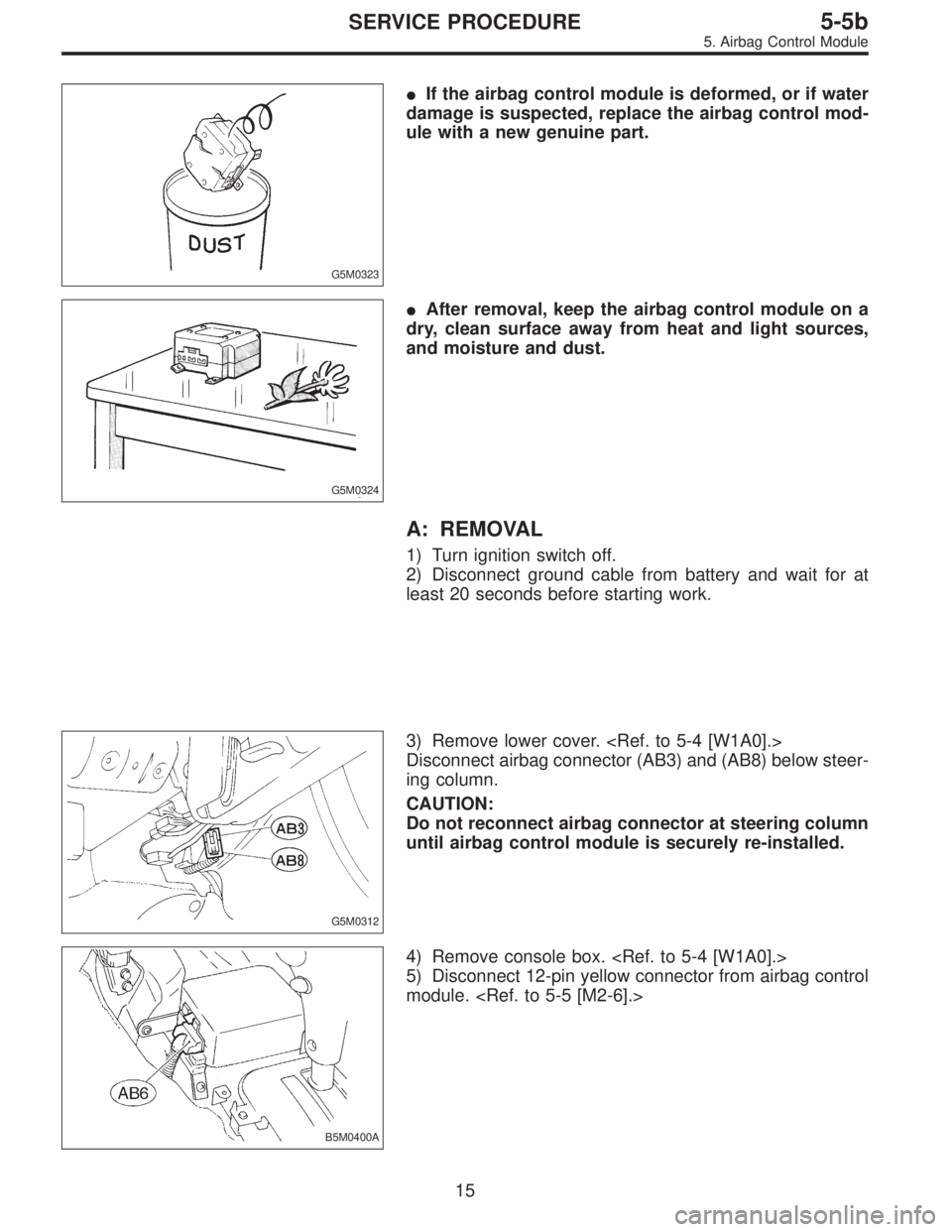
G5M0323
�If the airbag control module is deformed, or if water
damage is suspected, replace the airbag control mod-
ule with a new genuine part.
G5M0324
�After removal, keep the airbag control module on a
dry, clean surface away from heat and light sources,
and moisture and dust.
A: REMOVAL
1) Turn ignition switch off.
2) Disconnect ground cable from battery and wait for at
least 20 seconds before starting work.
G5M0312
3) Remove lower cover.
Disconnect airbag connector (AB3) and (AB8) below steer-
ing column.
CAUTION:
Do not reconnect airbag connector at steering column
until airbag control module is securely re-installed.
B5M0400A
4) Remove console box.
5) Disconnect 12-pin yellow connector from airbag control
module.
15
5-5bSERVICE PROCEDURE
5. Airbag Control Module
Page 1693 of 3342
 Using TORX®BIT T40 (Tamper resistant type), remove
two TORX®bolts.
Discard the old TORX®bolts.
CAUTION:
Use new TORX
®bolts during re-assembly.
B: INSTALLATION
Installation is in revers")
B5M0105
6) Using TORX®BIT T40 (Tamper resistant type), remove
two TORX®bolts.
Discard the old TORX®bolts.
CAUTION:
Use new TORX
®bolts during re-assembly.
B: INSTALLATION
Installation is in reverse order of removal procedures.
CAUTION:
Be sure to fully secure all airbag system connectors
during re-assembly and confirm that all green double
lock mechanisms are engaged.
6. Combination Switch
A: REMOVAL
1) Turn ignition switch off.
2) Disconnect ground cable from battery and wait for at
least 20 seconds before starting work.
G5M0312
3) Remove lower cover. Disconnect
airbag connector (AB3) and (AB8) below steering column.
CAUTION:
Do not reconnect airbag connector at steering column
until combination switch is securely re-installed.
4) Disconnect combination switch connectors from body
harness connector.
H5M0662A
5) Set front wheels in straight ahead position. Using
TORX®BIT T30, remove two TORX®bolts.
16
5-5bSERVICE PROCEDURE
5. Airbag Control Module - 6. Combination Switch
 If any of the airbag system parts such as sensors, air-
bag module, airbag control module and harness are dam-
aged or deformed, replace with new genuine parts.
G5M0292
2) Whe")
 Set front wheels in straight ahead position.
2) Turn ignition switch off.
3) Disconnect ground cable from battery and wait for at
least 20 seconds before starting work.
H5")
 Remove four bolts and then carefully remove airbag
module.
3) Refer to“CAUTION”for handling of a removed airbag
module.
B: INSTALLATION
Installation is in reverse order of removal proce")
 Remove four bolts and then carefully remove airbag
module.
3) Refer to“CAUTION”for handling of a removed airbag
module.
B: INSTALLATION
Installation is in reverse order of removal proce")