Page 3170 of 3342
 Start the engine.
4) Shift on the gear position, and keep the vehicle speed
at constant.
5) Measure signal voltage.
Specified voltage (V): 2 V, or more
NOTE:
�If the vehicle speed i")
G2M0931
B6M0287
3) Start the engine.
4) Shift on the gear position, and keep the vehicle speed
at constant.
5) Measure signal voltage.
Specified voltage (V): 2 V, or more
NOTE:
�If the vehicle speed increases, the width of amplitude
(W) decreases.
�If oscilloscope is not available, check input signal
(vehicle speed signal) by using a select monitor. (Refer to
the procedure as described below.)
�Using the select monitor:
(1) Set the vehicle on free roller, or lift-up the vehicle and
support with safety stands.
(2) Turn ignition switch to OFF and set select monitor.
(3) Turn ignition switch to ON.
(4) Turn cruise control main switch to ON.
(5) Set select monitor in“F01”or“F02”mode.
(6) Drive the vehicle at speed greater than 40 km/h (25
MPH).
(7) Check that vehicle speed indication on select moni-
tor and speedometer are equal.
NOTE:
�When there is a disconnection or short circuit in the har-
ness between the meter and the cruise control module, the
indicated value will be 0 to 1.0 km/h (0 to 0.6 MPH).
�In“F01”mode, vehicle speed is indicated in mile per
hour (MPH).
In“F02”mode, vehicle speed is indicated in kilometer per
hour (km/h).
B3M0250
3. PERFORM A CIRCUIT TEST BETWEEN
COMBINATION METER AND CRUISE CONTROL
MODULE.
1) Turn ignition switch to OFF.
2) Remove combination meter.
B6M0194B
3) Disconnect connector from cruise control module.
4) Measure resistance of harness connector between
combination meter and cruise control module.
Connector & terminal / Specified resistance:
(i10) No. 10—(B94) No. 19 / 10Ω, max.
24
6-2BODY ELECTRICAL SYSTEM
8. Diagnostics Chart with Trouble Code
Page 3171 of 3342
 Measure resistance of harness connector between
cruise control module and body to make sure that circuit
does not short.
Connector & terminal / Specified resistance:
(B94) No. 19—Body /")
B6M0248B
5) Measure resistance of harness connector between
cruise control module and body to make sure that circuit
does not short.
Connector & terminal / Specified resistance:
(B94) No. 19—Body / 1 MΩ, min.
B3M0289
4. CHECK VEHICLE SPEED SENSOR 2.
1) Disconnect connector from vehicle speed sensor 2.
2) Measure resistance between terminals of vehicle speed
sensor 2.
Terminals / Specified resistance:
No. 1—No. 2 / 350—450Ω
B3M0256
WARNING:
Be careful not to be caught up by the running wheels.
3) Set the vehicle on free roller, or lift-up the vehicle and
support with safety stands.
4) Drive the vehicle at speed greater than 20 km/h (12
MPH).
5) Measure voltage between terminals of vehicle speed
sensor 2.
Terminals / Specified voltage:
No. 1—No. 2 / 2 V, or more (AC range)
B3M0257
�Using an oscilloscope:
(1) Turn ignition switch to OFF.
(2) Set oscilloscope to vehicle speed sensor 2.
(3) Drive the vehicle at speed greater than 20 km/h (12
MPH).
(4) Measure signal voltage.
Specified voltage (V): 5 V, min.
B3M0254A
25
6-2BODY ELECTRICAL SYSTEM
8. Diagnostics Chart with Trouble Code
Page 3174 of 3342
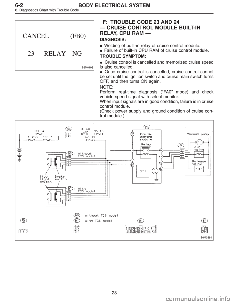
B6M0198
F: TROUBLE CODE 23 AND 24
—CRUISE CONTROL MODULE BUILT-IN
RELAY, CPU RAM—
DIAGNOSIS:
�Welding of built-in relay of cruise control module.
�Failure of built-in CPU RAM of cruise control module.
TROUBLE SYMPTOM:
�Cruise control is cancelled and memorized cruise speed
is also cancelled.
�Once cruise control is cancelled, cruise control cannot
be set until the ignition switch and cruise main switch turns
OFF, and then turns ON again.
NOTE:
Perform real-time diagnosis (“FA 0”mode) and check
vehicle speed signal with select monitor.
When input signals are in good condition, failure is in cruise
control module.
(Check power supply and ground condition of cruise con-
trol module.)
B6M0291
28
6-2BODY ELECTRICAL SYSTEM
8. Diagnostics Chart with Trouble Code
Page 3180 of 3342
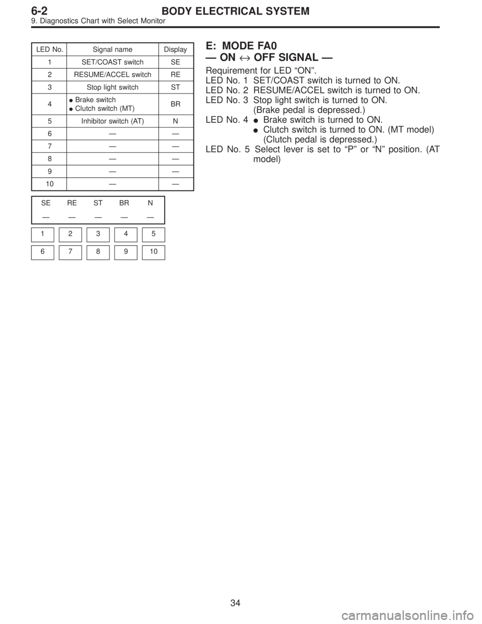
LED No. Signal name Display
1 SET/COAST switch SE
2 RESUME/ACCEL switch RE
3 Stop light switch ST
4�Brake switch
�Clutch switch (MT)BR
5 Inhibitor switch (AT) N
6——
7——
8——
9——
10——
SE RE ST BR N
—————
1
2345
678910
E: MODE FA0
—ON↔OFF SIGNAL—
Requirement for LED“ON”.
LED No. 1 SET/COAST switch is turned to ON.
LED No. 2 RESUME/ACCEL switch is turned to ON.
LED No. 3 Stop light switch is turned to ON.
(Brake pedal is depressed.)
LED No. 4�Brake switch is turned to ON.
�Clutch switch is turned to ON. (MT model)
(Clutch pedal is depressed.)
LED No. 5 Select lever is set to“P”or“N”position. (AT
model)
34
6-2BODY ELECTRICAL SYSTEM
9. Diagnostics Chart with Select Monitor
Page 3286 of 3342
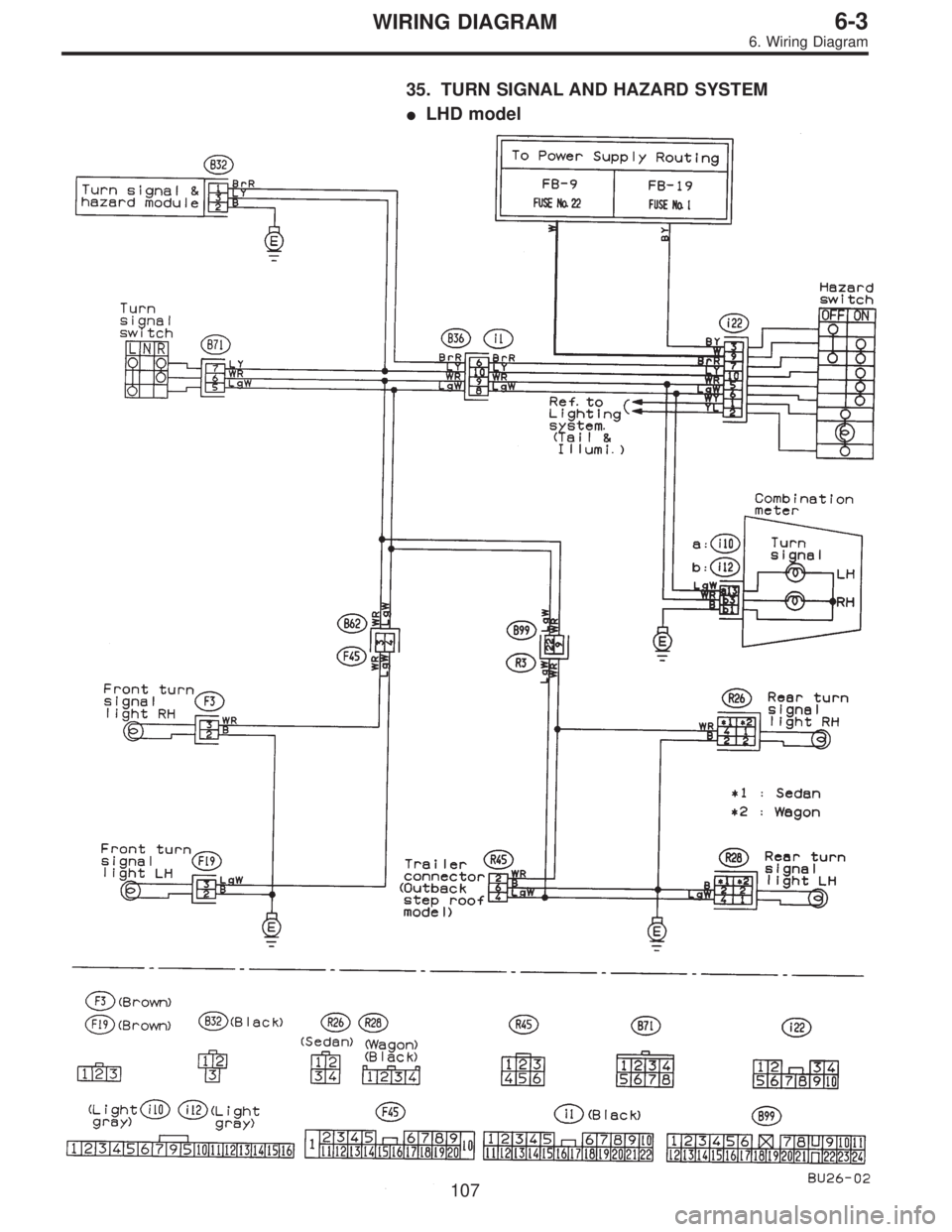
35. TURN SIGNAL AND HAZARD SYSTEM
�LHD model
107
6-3WIRING DIAGRAM
6. Wiring Diagram
Page 3287 of 3342
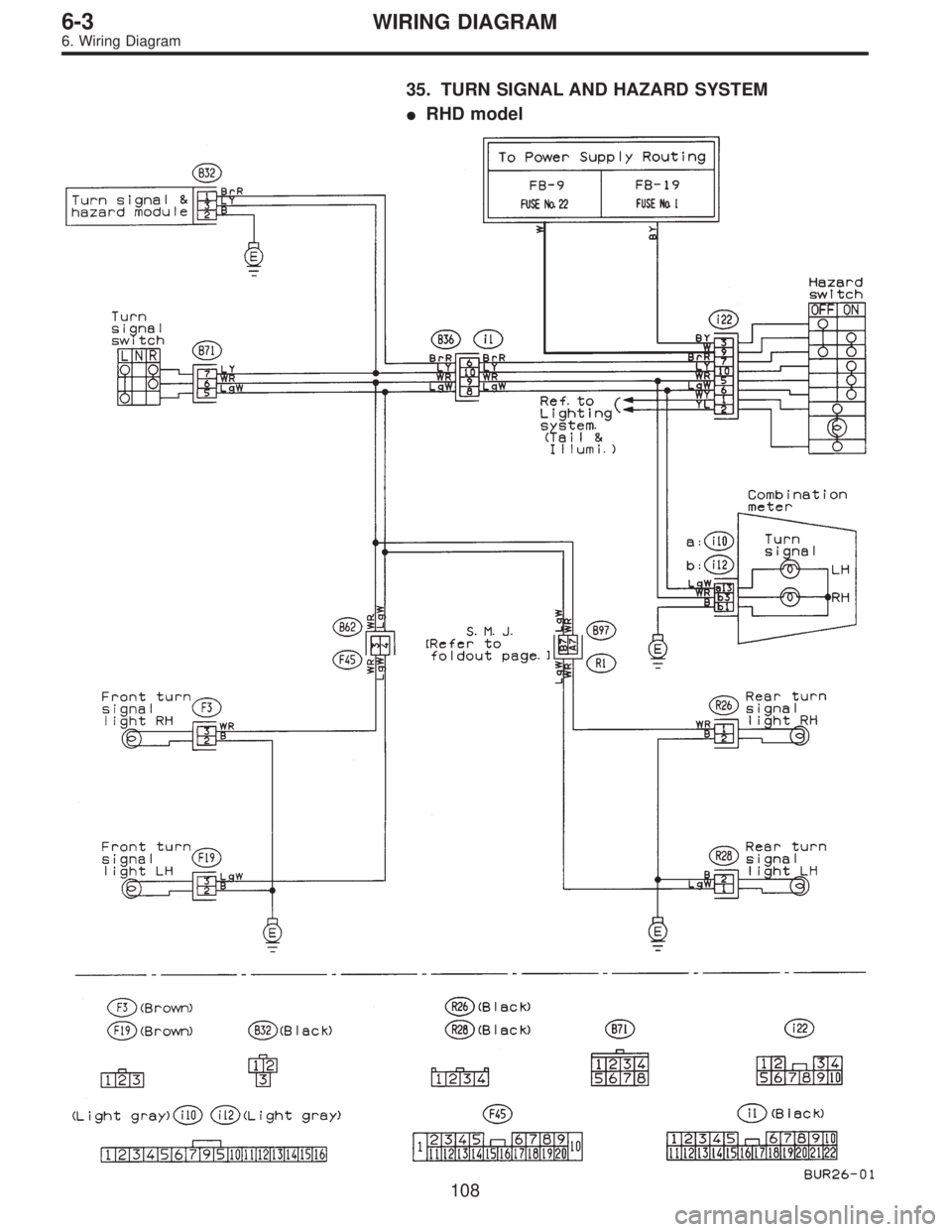
35. TURN SIGNAL AND HAZARD SYSTEM
�RHD model
108
6-3WIRING DIAGRAM
6. Wiring Diagram
Page 3297 of 3342

12 * B-2 P1 Floor wiring harness (With ABS model)
F2 20 Blue B-2 B100 Bulkhead wiring harnes")
Connector Connecting to
No. Pole Color Area No. Name
F120 Blue B-2 P1 Floor wiring harness (With TCS model)
12 * B-2 P1 Floor wiring harness (With ABS model)
F2 20 Blue B-2 B100 Bulkhead wiring harness (With ABS model)
F3 3 Brown B-1 Front turn signal and side marker light RH
F5 1 Black B-1 Horn
F62 * C-1 Front fog light RH
2 Brown C-1 Front fog light RH (Outback with step roof)
F7 3 Black B-1 Headlight RH
F8 2 Gray B-1
Hydraulic unit (ABS)
F9 8 Gray B-1
F10 4 * B-2 TCS motor relay
F11 6 * B-2 TCS valve relay
F12 2 Black B-2 TCS pressure switch
F13 2 Black B-2 TCS motor
F14 2 Gray B-2
Hydraulic unit (TCS)
F15 12 Gray B-2
F16 3 Black C-1 Sub fan motor
F17 3 Black C-2 Radiator main fan motor
F18 2 Gray C-3 Front hood switch (Security)
F19 3 Brown C-3 Front turn signal and side marker light LH
F212 * C-2 Front fog light LH
2 Brown C-2 Front fog light LH (Outback with step roof)
F23 3 Black C-2 Headlight LH
F24 3 Gray B-2 A/C compressor
F25 1 x 2 * B-2
Generator
F26 2 Gray B-2
F27 4 Black B-3 A/C fuse (Relay holder)
F28 4 Black B-3 A/C main fan relay-1 (Relay holder)
F29 4 Black B-3 A/C sub fan relay-2 (Relay holder)
F30 4 Black B-3 A/C main fan relay-2 (Relay holder)
F31 4 Black B-3 A/C relay (Relay holder)
F32 2 Green B-2 Front washer motor
F33 2 * B-3 Rear washer motor
F34 4 Black B-3 SBF holder
F35 8 Black B-3
M/B F36 3 * B-3
F37 2 Black B-3
F38 2 Black B-3
F39 1 Brown B-3
F40 10 Gray B-4
F/B F41 3 Gray B-4
F42 5 Gray B-4
F43 3 Orange B-4 A/C diode
F44 8 * B-3 B61
Bulkhead wiring harness
F45 20 * B-3 B62
F46 2 Black B-4 B108 Bulkhead wiring harness (Outback)
F47 1 Black C-3 Horn (TAIWAN model)
F48 6 * B-3 Shield joint connector (ABS)
F49 83 Black B-3 ABS control module
F50 6 Black B-1 ABS relay box
*: Non-colored
11 8
6-3WIRING DIAGRAM
8. Electrical Wiring Harness and Ground Point
Page 3299 of 3342
Connector Connecting to
No. Pole Color Area No. Name
F3 3 Brown B-1 Front turn signal and side marker light RH
F5 1 Black B-1 Horn
F7 3 Black B-1 Headlight RH
F16 3 Black C-1 Sub fan motor
F17 3 Black C-2 Radiator main fan motor
F19 3 Brown C-3 Front turn signal and side marker light LH
F20 1 Black C-2 Horn
F23 3 Black C-2 Headlight LH
F24 1 Black B-2 A/C compressor
F25 1 x 2 * B-2
Generator
F26 2 Gray B-2
F27 4 Black B-3 A/C fuse (Relay holder)
F28 4 Black B-3 A/C main fan relay-1 (Relay holder)
F29 4 Black B-3 A/C sub fan relay-2 (Relay holder)
F30 4 Black B-3 A/C main fan relay-2 (Relay holder)
F31 4 Black B-3 A/C relay (Relay holder)
F35 8 Black B-3
M/B
F38 2 Black B-3
F40 10 Gray B-2
F/B
F42 5 Gray B-2
F43 3 Orange B-2 A/C diode
F44 8 * B-2 B61
Bulkhead wiring harness
F45 20 * B-2 B62
F47 2 Gray C-2 A/C pressure switch
F48 2 Blue B-2 Thermal protector
*: Non-colored
120
6-3WIRING DIAGRAM
8. Electrical Wiring Harness and Ground Point