Page 2475 of 3342

One-way clutch (3-")
Overrunning clutch
Drive pinion
Crown gear
Axle shaft
Differential gear
Final gear
Seal pipe
Oil pump
High clutch
Band brake
Low & reverse clutch
Reverse clutch
One-way clutch (1-2)
One-way clutch (3-4)
Double oil seal
Input shaft
Output shaft
Planetary gear
Reduction gear
Drive plate
Torque converter one-way clutch
Lock-up facing
Lock-up damper
ATF deterioration
ATF level too high or too low
Differential gear oil level too high or too low
Engine performance
Engine speed signal
Parking brake mechanism
Problem parts
30 31 32 33 34 35 36 37 38 39 40 41 42 43 44 45 46 47 48 49 50 51 52 53 54 55 56 57 58 Symptom
XEngine brake is not effected when select
lever is in“3”or“2”range.
XEngine brake is not effected when select
lever is in“1”range.
Shift characteristics are erroneous.
X X No lock-up occurs.
Vehicle cannot be set in“D”range power
mode.
“D”range power mode cannot be released.
X Parking brake is not effected.
XShift lever cannot be moved or is hard to
move from“P”range.
Select lever is hard to move.
Select lever is too light to move (unreason-
able resistance).
X ATF spurts out.
X Differential oil spurts out.
X X Differential oil level changes excessively.
X XXXX X XOdor is produced from oil supply pipe.
XXXShock occurs when select lever is moved
from“1”to“2”range.
XSlippage occurs when select lever is moved
from“1”to“2”range.
XX X XShock occurs when select lever is moved
from“2”to“3”range.
XXSlippage occurs when select lever is moved
from“2”to“3”range.
XX XXShock occurs when select lever is moved
from“3”to“4”range.
XSlippage occurs when select lever is moved
from“3”to“4”range.
XX XShock occurs when select lever is moved
from“3”to“2”range.
XShock occurs when select lever is moved
from“D”to“1”range.
XXShock occurs when select lever is moved
from“2”to“1”range.
XXShock occurs when accelerator pedal is
released at medium speeds.
XXVibration occurs during straight-forward
operation.
Select lever slips out of position during
acceleration or while driving on rough terrain.
XVibration occurs during turns (tight corner
“braking”phenomenon).
Front wheel slippage occurs during standing
starts.
Vehicle is not set in FWD mode.
30 31 32 33 34 35 36 37 38 39 40 41 42 43 44 45 46 47 48 49 50 51 52 53 54 55 56 57 58
71
3-2AUTOMATIC TRANSMISSION AND DIFFERENTIAL
9. General Diagnostic Table
Page 2547 of 3342
B4M0461A
13. CHECK GROUND CIRCUIT OF MOTOR.
1) Turn ignition switch OFF.
2) Disconnect motor connector.
3) Measure resistance between motor connector and
body.
Connector & terminal / Specified resistance:
(F13) No. 1—body / 1Ωor less
NOTE:
The check can also be made by analyzing the waves of the
motor sensor output signal with oscilloscope during the
TCS sequence control operation. If the ECM female con-
nector end gives correct value, skip steps 6 through 9
above.
If not, operate the TCS sequence control again and mea-
sure the value at motor sensor male connector end with the
motor sensor connector removed. If the value is OK, pro-
ceed with steps 8 and 9 above.
71
4-4bBRAKES
8. Diagnostics Chart with Trouble Code
Page 2566 of 3342

—
�Compare speedometer with monitor indications.
�F04: RL wheel speed is indicated in mile per hour (mile/
h).
�F08: RL wheel speed i")
B4M0483
F: MODE F04 AND F08
—REAR LEFT WHEEL SPEED SIGNAL (RL)
—
�Compare speedometer with monitor indications.
�F04: RL wheel speed is indicated in mile per hour (mile/
h).
�F08: RL wheel speed is indicated in kilometer per hour
(km/h).
NOTE:
The monitor as shown, indicates that RL wheel speed is 50
mile/h.
B4M0484
G: MODE F09
—PEDAL STROKE SENSOR SIGNAL (PSS)
—
�Indicates the output step number of the pedal stroke
sensor.
LED No. Signal name Display
1 TCS OFF switch OF
2 Stop light switch B1
3 Valve relay signal VR
4 Valve relay monitor VM
5 Motor relay signal MR
6 Motor sensor MS
7 Brake fluid level sensor FS
8——
9——
10——
OF B1 VR VM MR
MS FS———
1
2345
678910
H: MODE FA0
—ON↔OFF SIGNAL—
Requirement for LED“ON”
LED No. 1 T.C.S OFF switch is turned ON.
LED No. 2 Stop light switch is turned ON. (With brake
pedal depressed.)
LED No. 3 Valve relay is turned OFF.
LED No. 4 Valve relay is turned OFF.
LED No. 5 Motor relay is turned ON.
LED No. 6 Motor is rotating.
LED No. 7 Brake fluid level sensor is turned ON. (Brake
fluid is insufficient.)
90
4-4bBRAKES
9. Select Monitor Function Mode
Page 2647 of 3342
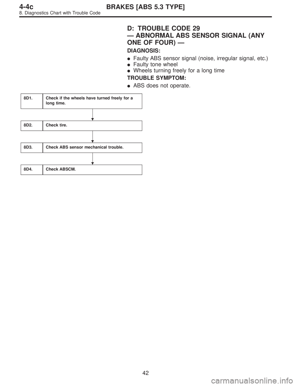
D: TROUBLE CODE 29
—ABNORMAL ABS SENSOR SIGNAL (ANY
ONE OF FOUR)—
DIAGNOSIS:
�Faulty ABS sensor signal (noise, irregular signal, etc.)
�Faulty tone wheel
�Wheels turning freely for a long time
TROUBLE SYMPTOM:
�ABS does not operate.
8D1.Check if the wheels have turned freely for a
long time.
8D2.Check tire.
8D3.Check ABS sensor mechanical trouble.
8D4.Check ABSCM.
�
�
�
42
4-4cBRAKES [ABS 5.3 TYPE]
8. Diagnostics Chart with Trouble Code
Page 2665 of 3342
B4M0838A
8G1
CHECK GROUND CIRCUIT OF ABSCM.
1) Turn ignition switch to OFF.
2) Disconnect connector from ABSCM.
3) Measure resistance between ABSCM and chassis
ground.
: Connector & terminal
(F49) No. 1—Chassis ground
(F49) No. 55—Chassis ground
Is resistance less than 0.5Ω?
: Go to step8G2.
: Repair ABSCM ground harness.
8G2CHECK POOR CONTACT IN CONNEC-
TORS BETWEEN BATTERY, IGNITION
SWITCH AND ABSCM.
: Is there poor contact in connectors between
battery, ignition switch and ABSCM?
: Repair connector.
: Go to step8G3.
8G3
CHECK SOURCES OF SIGNAL NOISE.
: Is the car telephone or the wireless trans-
mitter properly installed?
: Go to next.
: Properly install the car telephone or the wireless
transmitter.
: Are noise sources (such as an antenna)
installed near the sensor harness?
: Install the noise sources apart from the sensor
harness.
: Go to step8G4.
60
4-4cBRAKES [ABS 5.3 TYPE]
8. Diagnostics Chart with Trouble Code
Page 2722 of 3342
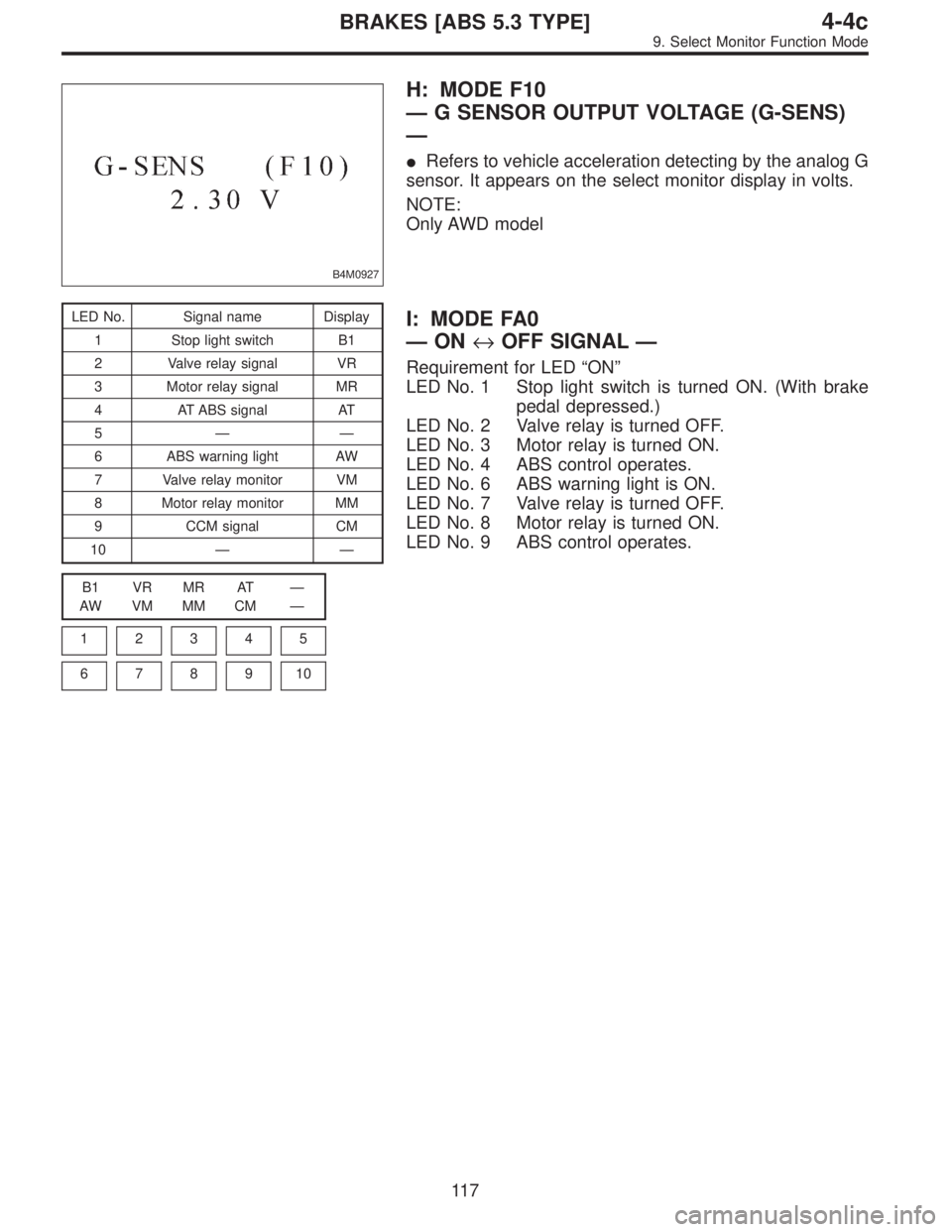
B4M0927
H: MODE F10
—G SENSOR OUTPUT VOLTAGE (G-SENS)
—
�Refers to vehicle acceleration detecting by the analog G
sensor. It appears on the select monitor display in volts.
NOTE:
Only AWD model
LED No. Signal name Display
1 Stop light switch B1
2 Valve relay signal VR
3 Motor relay signal MR
4 AT ABS signal AT
5——
6 ABS warning light AW
7 Valve relay monitor VM
8 Motor relay monitor MM
9 CCM signal CM
10——
B1 VR MR AT—
AW VM MM CM—
1
2345
678910
I: MODE FA0
—ON↔OFF SIGNAL—
Requirement for LED“ON”
LED No. 1 Stop light switch is turned ON. (With brake
pedal depressed.)
LED No. 2 Valve relay is turned OFF.
LED No. 3 Motor relay is turned ON.
LED No. 4 ABS control operates.
LED No. 6 ABS warning light is ON.
LED No. 7 Valve relay is turned OFF.
LED No. 8 Motor relay is turned ON.
LED No. 9 ABS control operates.
11 7
4-4cBRAKES [ABS 5.3 TYPE]
9. Select Monitor Function Mode
Page 2726 of 3342
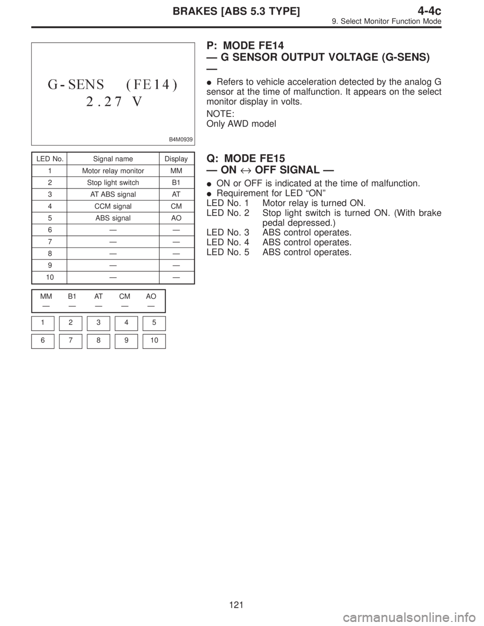
B4M0939
P: MODE FE14
—G SENSOR OUTPUT VOLTAGE (G-SENS)
—
�Refers to vehicle acceleration detected by the analog G
sensor at the time of malfunction. It appears on the select
monitor display in volts.
NOTE:
Only AWD model
LED No. Signal name Display
1 Motor relay monitor MM
2 Stop light switch B1
3 AT ABS signal AT
4 CCM signal CM
5 ABS signal AO
6——
7——
8——
9——
10——
MM B1 AT CM AO
—————
1
2345
678910
Q: MODE FE15
—ON↔OFF SIGNAL—
�ON or OFF is indicated at the time of malfunction.
�Requirement for LED“ON”
LED No. 1 Motor relay is turned ON.
LED No. 2 Stop light switch is turned ON. (With brake
pedal depressed.)
LED No. 3 ABS control operates.
LED No. 4 ABS control operates.
LED No. 5 ABS control operates.
121
4-4cBRAKES [ABS 5.3 TYPE]
9. Select Monitor Function Mode
Page 2757 of 3342
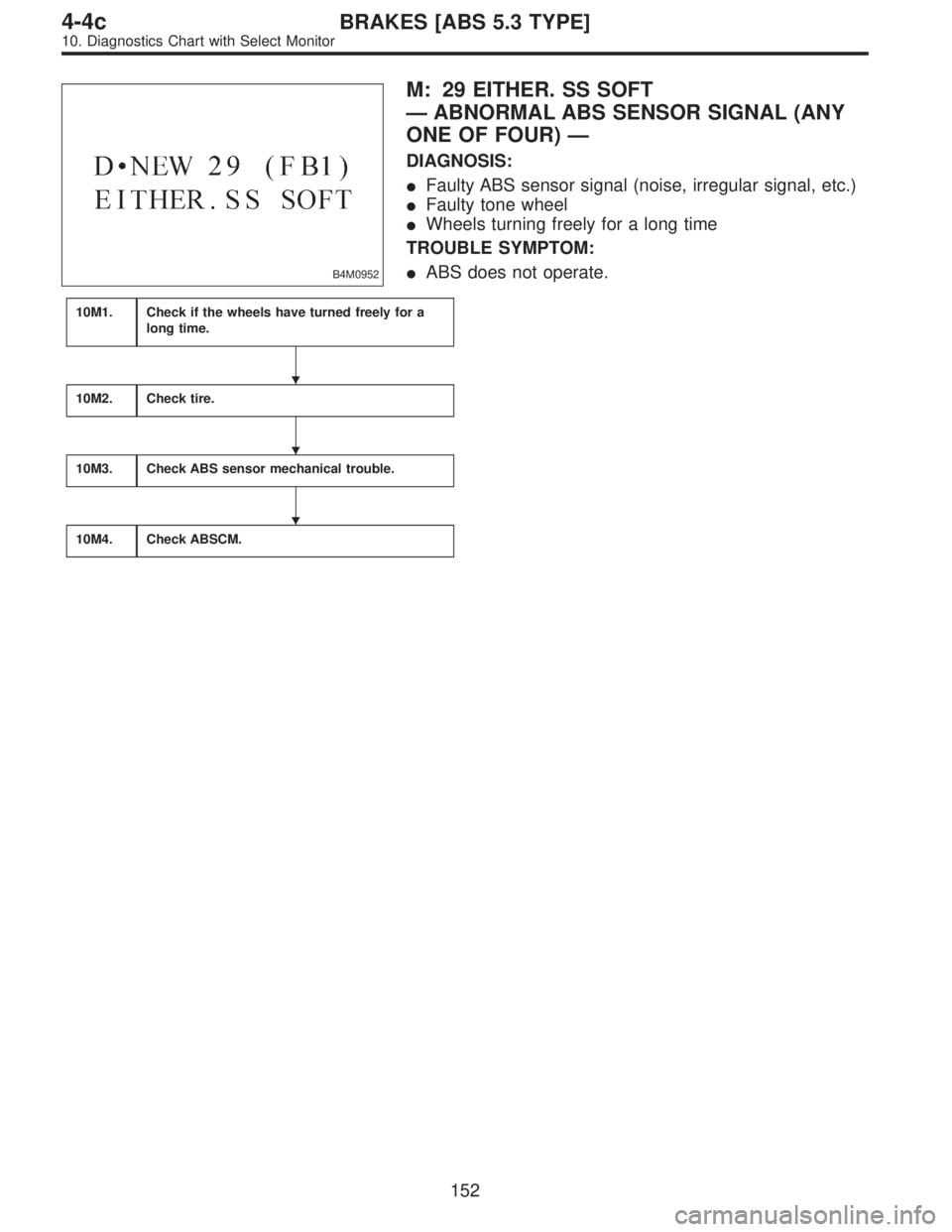
B4M0952
M: 29 EITHER. SS SOFT
—ABNORMAL ABS SENSOR SIGNAL (ANY
ONE OF FOUR)—
DIAGNOSIS:
�Faulty ABS sensor signal (noise, irregular signal, etc.)
�Faulty tone wheel
�Wheels turning freely for a long time
TROUBLE SYMPTOM:
�ABS does not operate.
10M1.Check if the wheels have turned freely for a
long time.
10M2.Check tire.
10M3.Check ABS sensor mechanical trouble.
10M4.Check ABSCM.
�
�
�
152
4-4cBRAKES [ABS 5.3 TYPE]
10. Diagnostics Chart with Select Monitor
 Turn ignition switch OFF.
2) Disconnect motor connector.
3) Measure resistance between motor connector and
body.
Connector & terminal / Specified resista")
 Turn ignition switch to OFF.
2) Disconnect connector from ABSCM.
3) Measure resistance between ABSCM and chassis
ground.
: Connector & terminal
(F49) No.")