Page 2787 of 3342
B4M0838A
10V1
CHECK GROUND CIRCUIT OF ABSCM.
1) Turn ignition switch to OFF.
2) Disconnect connector from ABSCM.
3) Measure resistance between ABSCM and chassis
ground.
: Connector & terminal
(F49) No. 1—Chassis ground
(F49) No. 55—Chassis ground
Is resistance less than 0.5Ω?
: Go to step10V2.
: Repair ABSCM ground harness.
10V2CHECK POOR CONTACT IN CONNEC-
TORS BETWEEN BATTERY, IGNITION
SWITCH AND ABSCM.
: Is there poor contact in connectors between
battery, ignition switch and ABSCM?
: Repair connector.
: Go to step10V3.
10V3
CHECK SOURCES OF SIGNAL NOISE.
: Is the car telephone or the wireless trans-
mitter properly installed?
: Go to next.
: Properly install the car telephone or the wireless
transmitter.
: Are noise sources (such as an antenna)
installed near the sensor harness?
: Install the noise sources apart from the sensor
harness.
: Go to step10V4.
182
4-4cBRAKES [ABS 5.3 TYPE]
10. Diagnostics Chart with Select Monitor
Page 2913 of 3342
 Raise all four wheels of ground.
2) Turn ignition switch OFF.
3) Connect the oscilloscope to the connector (F1) or con-
nector (B100).
4) Turn ignition switch ON.
B4M12")
8I5
CHECK ABS SENSOR SIGNAL.
1) Raise all four wheels of ground.
2) Turn ignition switch OFF.
3) Connect the oscilloscope to the connector (F1) or con-
nector (B100).
4) Turn ignition switch ON.
B4M1242A
5) Rotate wheels and measure voltage at specified fre-
quency.
NOTE:
When this inspection is completed, the ABS control mod-
ule sometimes stores the trouble code 29.
Connector & terminal
Trouble code 22 / (B100) No. 12 (+)—No. 13 (�):
Trouble code 24 / (B100) No. 3 (+)—No.4(�):
Trouble code 26 / (F1) No. 4 (+)—No.5(�):
Trouble code 28 / (F1) No. 1 (+)—No.2(�):
Specified voltage: 0.12—1 V (When it is 20 Hz.)
: Is oscilloscope pattern smooth, as shown in
figure?
: Go to step8I9.
: Go to step8I6.
8I6CHECK CONTAMINATION OF ABS SEN-
SOR OR TONE WHEEL.
Remove disc rotor or drum from hub in accordance with
trouble code.
: Is the ABS sensor pole piece or the tone
wheel contaminated by dirt or other foreign
matter?
: Thoroughly remove dirt or other foreign matter.
: Go to step8I7.
8I7CHECK DAMAGE OF ABS SENSOR OR
TONE WHEEL.
: Are there broken or damaged in the ABS
sensor pole piece or the tone wheel?
: Replace ABS sensor or tone wheel.
: Go to step8I8.
37
4-4dBRAKES [ABS 5.3i TYPE]
8. Diagnostics Chart with Trouble Code by ABS Warning Light
Page 2918 of 3342
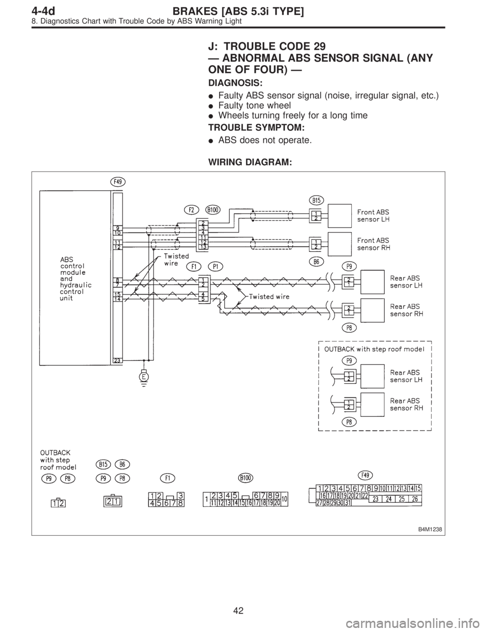
J: TROUBLE CODE 29
—ABNORMAL ABS SENSOR SIGNAL (ANY
ONE OF FOUR)—
DIAGNOSIS:
�Faulty ABS sensor signal (noise, irregular signal, etc.)
�Faulty tone wheel
�Wheels turning freely for a long time
TROUBLE SYMPTOM:
�ABS does not operate.
WIRING DIAGRAM:
B4M1238
42
4-4dBRAKES [ABS 5.3i TYPE]
8. Diagnostics Chart with Trouble Code by ABS Warning Light
Page 2920 of 3342

: Are the tone wheel installation bolts tight-
ened securely?
: Go to step8J7.
: Tighten tone wheel in")
8J6CHECK INSTALLATION OF TONE
WHEEL.
Tightening torque:
13±3 N⋅m (1.3±0.3 kg-m, 9±2.2 ft-lb)
: Are the tone wheel installation bolts tight-
ened securely?
: Go to step8J7.
: Tighten tone wheel installation bolts securely.
G4M0700
8J7
CHECK ABS SENSOR GAP.
Measure tone wheel to pole piece gap over entire perim-
eter of the wheel.
: Is the gap within the specifications shown
in the following table?
SpecificationsFront wheel Rear wheel
0.9—1.4 mm
(0.035—0.055 in)0.7—1.2 mm
(0.028—0.047 in)
G4M0701
: Go to step8J8.
: Adjust the gap.
NOTE:
Adjust the gap using spacer (Part No. 26755AA000). If
spacers cannot correct the gap, replace worn sensor or
worn tone wheel.
8J8
CHECK OSCILLOSCOPE.
: Is an oscilloscope available?
: Go to step8J9.
: Go to step8J10.
8J9
CHECK ABS SENSOR SIGNAL.
1) Raise all four wheels of ground.
2) Turn ignition switch OFF.
3) Connect the oscilloscope to the connector (F1) or con-
nector (B100).
4) Turn ignition switch ON.
44
4-4dBRAKES [ABS 5.3i TYPE]
8. Diagnostics Chart with Trouble Code by ABS Warning Light
Page 2930 of 3342
 Turn ignition switch to OFF.
2) Disconnect connector from ABSCM&H/U.
3) Measure resistance between ABSCM&H/U and chassis
ground.
Connector & terminal")
B4M1243A
8S1CHECK GROUND CIRCUIT OF
ABSCM&H/U.
1) Turn ignition switch to OFF.
2) Disconnect connector from ABSCM&H/U.
3) Measure resistance between ABSCM&H/U and chassis
ground.
Connector & terminal
(F49) No. 23—Chassis ground:
: Is the resistance less than 0.5Ω?
: Go to step8S2.
: Repair ABSCM&H/U ground harness.
8S2CHECK POOR CONTACT IN CONNEC-
TORS.
: Is there poor contact in connectors between
battery, ignition switch and ABSCM&H/U?
: Repair connector.
: Go to step8S3.
8S3
CHECK SOURCES OF SIGNAL NOISE.
: Is the car telephone or the wireless trans-
mitter properly installed?
: Go to step8S4.
: Properly install the car telephone or the wireless
transmitter.
8S4
CHECK SOURCES OF SIGNAL NOISE.
: Are noise sources (such as an antenna)
installed near the sensor harness?
: Install the noise sources apart from the sensor
harness.
: Go to step8S5.
8S5
CHECK ABSCM&H/U.
1) Connect all connectors.
2) Erase the memory.
3) Perform inspection mode.
4) Read out the trouble code.
: Is the same trouble code as in the current
diagnosis still being output?
: Replace ABSCM&H/U.
: Go to step8S6.
54
4-4dBRAKES [ABS 5.3i TYPE]
8. Diagnostics Chart with Trouble Code by ABS Warning Light
Page 2961 of 3342
LED No. Signal name Display
1 Stop light switch B1
2 Valve relay signal VR
3 Motor relay signal MR
4 AT ABS signal AT
5——
6 ABS warning light AW
7 Valve relay monitor VM
8 Motor relay monitor MM
9 CCM signal CM
10——
B1 VR MR AT—
AW VM MM CM—
1
2345
678910
I: MODE FA0
—ON↔OFF SIGNAL—
Requirement for LED“ON”
LED No. 1 Stop light switch is turned ON. (With brake
pedal depressed.)
LED No. 2 Valve relay is turned OFF.
LED No. 3 Motor relay is turned ON.
LED No. 4 ABS control operates.
LED No. 6 ABS warning light is ON.
LED No. 7 Valve relay is turned OFF.
LED No. 8 Motor relay is turned ON.
LED No. 9 ABS control operates.
85
4-4dBRAKES [ABS 5.3i TYPE]
9. Select Monitor Function Mode
Page 2965 of 3342
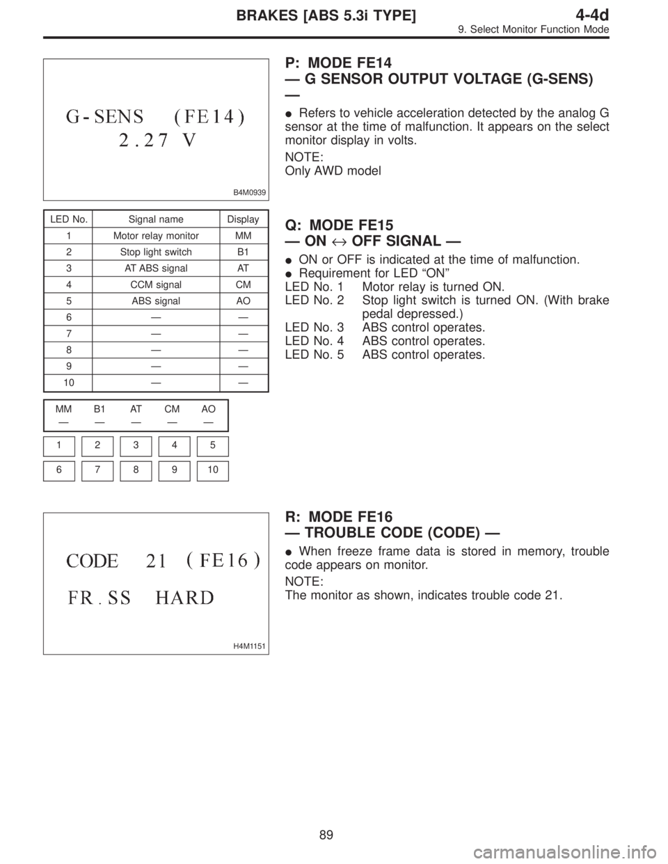
B4M0939
P: MODE FE14
—G SENSOR OUTPUT VOLTAGE (G-SENS)
—
�Refers to vehicle acceleration detected by the analog G
sensor at the time of malfunction. It appears on the select
monitor display in volts.
NOTE:
Only AWD model
LED No. Signal name Display
1 Motor relay monitor MM
2 Stop light switch B1
3 AT ABS signal AT
4 CCM signal CM
5 ABS signal AO
6——
7——
8——
9——
10——
MM B1 AT CM AO
—————
1
2345
678910
Q: MODE FE15
—ON↔OFF SIGNAL—
�ON or OFF is indicated at the time of malfunction.
�Requirement for LED“ON”
LED No. 1 Motor relay is turned ON.
LED No. 2 Stop light switch is turned ON. (With brake
pedal depressed.)
LED No. 3 ABS control operates.
LED No. 4 ABS control operates.
LED No. 5 ABS control operates.
H4M1151
R: MODE FE16
—TROUBLE CODE (CODE)—
�When freeze frame data is stored in memory, trouble
code appears on monitor.
NOTE:
The monitor as shown, indicates trouble code 21.
89
4-4dBRAKES [ABS 5.3i TYPE]
9. Select Monitor Function Mode
Page 2987 of 3342

B4M0922
10L1CHECK OUTPUT OF ABS SENSOR
USING SELECT MONITOR.
Read the ABS sensor output corresponding to the faulty
system in the select monitor function mode.
NOTE:
The select monitor display shows that the front right wheel
is rotating at 30 km/h.
: Does the speed indicated on the display
change in response to the speedometer
reading during acceleration/deceleration
when the steering wheel is in the straight-
ahead position?
: Go to step10L2.
: Go to step10L8.
10L2CHECK POOR CONTACT IN CONNEC-
TORS.
Turn ignition switch to OFF.
: Is there poor contact in connectors between
ABSCM&H/U and ABS sensor?
: Repair connector.
: Go to step10L3.
10L3
CHECK SOURCES OF SIGNAL NOISE.
: Is the car telephone or the wireless trans-
mitter properly installed?
: Go to step10L4.
: Properly install the car telephone or the wireless
transmitter.
10L4
CHECK SOURCES OF SIGNAL NOISE.
: Are noise sources (such as an antenna)
installed near the sensor harness?
: Install the noise sources apart from the sensor
harness.
: Go to step10L5.
111
4-4dBRAKES [ABS 5.3i TYPE]
10. Diagnostics Chart with Select Monitor
 Turn ignition switch to OFF.
2) Disconnect connector from ABSCM.
3) Measure resistance between ABSCM and chassis
ground.
: Connector & terminal
(F49) No")