Page 2257 of 3342
 Turn ignition switch to OFF.
2) Connect test mode connector at the lower portion of
instrument panel (on the driver’s side), to the side of the
center")
OBD0736A
10CW1
CHECK OUTPUT SIGNAL FROM ECM.
1) Turn ignition switch to OFF.
2) Connect test mode connector at the lower portion of
instrument panel (on the driver’s side), to the side of the
center console box.
3) Turn ignition switch to ON.
B2M0608A
4) Measure voltage between ECM and chassis ground.
: Connector & terminal
(B84) No. 74 (+)—Chassis ground:
Does voltage change between 0 and 10
volts?
NOTE:
Radiator fan relay operation check can be executed using
Subaru Select Monitor (Function mode: FD03). For
procedure, refer to“COMPULSORY VALVE OPERATION
CHECK MODE”.
: Go to step10CW2.
: Even if MIL lights up, the circuit has returned to a
normal condition at this time. In this case, repair
poor contact in ECM connector.
B2M0611A
10CW2CHECK SHORT CIRCUIT IN RADIATOR
FAN RELAY 1 CONTROL CIRCUIT.
1) Turn ignition switch to OFF.
2) Remove main fan relay 1 and sub fan relay 1. (with A/C
models)
Remove main fan relay. (without A/C models)
3) Disconnect test mode connector.
4) Turn ignition switch to ON.
5) Measure voltage between ECM and chassis ground.
: Connector & terminal
(B84) No. 74 (+)—Chassis ground (�):
Is the voltage more than 10 V?
: Repair battery short circuit in radiator fan relay 1
control circuit. After repair, replace ECM.
: Go to next.
: Is there poor contact in ECM connector?
: Repair poor contact in ECM connector.
: Replace ECM.
406
2-7ON-BOARD DIAGNOSTICS II SYSTEM
10. Diagnostic Chart with Trouble Code for LHD Vehicles
Page 2262 of 3342
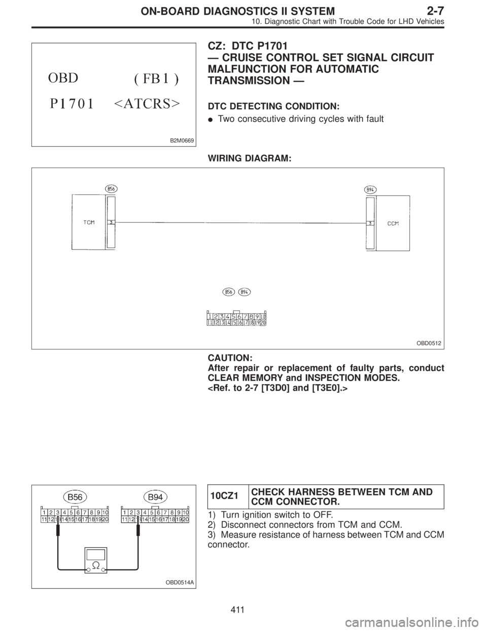
B2M0669
CZ: DTC P1701
—CRUISE CONTROL SET SIGNAL CIRCUIT
MALFUNCTION FOR AUTOMATIC
TRANSMISSION—
DTC DETECTING CONDITION:
�Two consecutive driving cycles with fault
WIRING DIAGRAM:
OBD0512
CAUTION:
After repair or replacement of faulty parts, conduct
CLEAR MEMORY and INSPECTION MODES.
OBD0514A
10CZ1CHECK HARNESS BETWEEN TCM AND
CCM CONNECTOR.
1) Turn ignition switch to OFF.
2) Disconnect connectors from TCM and CCM.
3) Measure resistance of harness between TCM and CCM
connector.
411
2-7ON-BOARD DIAGNOSTICS II SYSTEM
10. Diagnostic Chart with Trouble Code for LHD Vehicles
Page 2322 of 3342
 Turn ignition switch to ON.
2) Measure voltage between ECM and chassis ground.
: Connector & terminal
(B84) No. 35 (+)—Chassis ground (�):
Is the volt")
H2M1370B
11AU1
CHECK OUTPUT SIGNAL FROM ECM.
1) Turn ignition switch to ON.
2) Measure voltage between ECM and chassis ground.
: Connector & terminal
(B84) No. 35 (+)—Chassis ground (�):
Is the voltage more than 10 V?
: Go to next.
: Go to step11AU2.
: Is there poor contact in ECM connector?
: Repair poor contact in ECM connector.
: Even if MIL lights up, the circuit has returned to a
normal condition at this time. (However, the pos-
sibility of poor contact still remains.)
NOTE:
In this case, repair the following:
�Poor contact in vent control solenoid valve connector
�Poor contact in ECM connector
�Poor contact in coupling connectors (B97 and R57)
H2M1239C
11AU2CHECK HARNESS BETWEEN VENT
CONTROL SOLENOID VALVE AND ECM
CONNECTOR.
1) Turn ignition switch to OFF.
2) Disconnect connectors from vent control solenoid valve
and ECM.
3) Measure resistance of harness between vent control
solenoid valve connector and chassis ground.
: Connector & terminal
(R69) No. 2—Chassis ground:
Is the resistance less than 10Ω?
: Repair ground short circuit in harness between
ECM and vent control solenoid valve connector.
: Go to next step 4).
H2M1371B
4) Measure resistance of harness between ECM and vent
control solenoid valve connector.
: Connector & terminal
(B84) No. 35—(R69) No. 2:
Is the voltage less than 1Ω?
: Go to step11AU3.
: Repair harness and connector.
471
2-7ON-BOARD DIAGNOSTICS II SYSTEM
11. Diagnostic Chart with Trouble Code for RHD Vehicles
Page 2326 of 3342
 Turn ignition switch to OFF.
2) Remove fuel filler cap.
3) Install fuel filler cap.
4) Connect Subaru S")
B2M1016A
11 AW 1CONNECT SUBARU SELECT MONITOR
OR THE OBD-II GENERAL SCAN TOOL,
AND READ DATA.
1) Turn ignition switch to OFF.
2) Remove fuel filler cap.
3) Install fuel filler cap.
4) Connect Subaru Select Monitor or the OBD-II general
scan tool to data link connector.
5) Turn ignition switch to ON and Subaru Select Monitor or
the OBD-II general scan tool switch to ON.
H2M1326
6) Read the data on Subaru Select Monitor or the OBD-II
general scan tool.
�Subaru Select Monitor
Designate mode using function key.
Function mode: F43
�F43: Display shows pressure signal value sent from fuel
tank pressure sensor.
: Is the value less than�2.8 kPa in function
mode F43?
: Go to step11 AW 2.
: Even if MIL lights up, the circuit has returned to a
normal condition at this time.
�OBD-II general scan tool
For detailed operation procedures, refer to the OBD-II Gen-
eral Scan Tool Instruction Manual.
B2M0535A
11 AW 2CHECK INPUT SIGNAL FOR ECM.
(USING VOLTAGE METER AND SUBARU
SELECT MONITOR.)
1) Measure voltage between ECM connector and chassis
ground.
: Connector & terminal
(B84) No. 21 (+)—Chassis ground (�):
Is the voltage more than 4.5 V?
: Go to next step 2).
: Go to next.
475
2-7ON-BOARD DIAGNOSTICS II SYSTEM
11. Diagnostic Chart with Trouble Code for RHD Vehicles
Page 2327 of 3342

B2M0535A
: Does the voltage change more than 4.5 V by
shaking harness and connector of ECM
while monitoring the value with voltage
meter?
: Repair poor contact in ECM connector.
: Contact with SOA service.
NOTE:
Inspection by DTM is required, because probable cause is
deterioration of multiple parts.
H2M1374B
2) Measure voltage between ECM and chassis ground.
: Connector & terminal
(B84) No. 4 (+)—Chassis ground (�):
Is the voltage less than 0.2 V?
: Go to step11 AW 3.
: Go to next step 3).
H2M1326
3) Read data on Subaru Select Monitor.
�Subaru Select Monitor
Designate mode using function key.
Function mode: F43
�F43: Display shows pressure signal value sent from fuel
tank pressure sensor.
: Does the value change more than�2.8 kPa
by shaking harness and connector of ECM
while monitoring the value with Subaru
select monitor?
: Repair poor contact in ECM connector.
: Go to step11 AW 3.
B2M0927
11 AW 3CHECK HARNESS BETWEEN ECM AND
FUEL TANK PRESSURE SENSOR CON-
NECTOR.
1) Turn ignition switch to OFF.
2) Detach right side rear quarter trim panel.
3) Remove right side rear quarter trim pocket.
4) Detach right side rear quarter insulator.
476
2-7ON-BOARD DIAGNOSTICS II SYSTEM
11. Diagnostic Chart with Trouble Code for RHD Vehicles
Page 2331 of 3342
 Turn ignition switch to OFF.
2) Remove fuel filler cap.
3) Install fuel filler cap.
4) Connect Subaru Sel")
B2M1016A
11AX1CONNECT SUBARU SELECT MONITOR
OR THE OBD-II GENERAL SCAN TOOL,
AND READ DATA.
1) Turn ignition switch to OFF.
2) Remove fuel filler cap.
3) Install fuel filler cap.
4) Connect Subaru Select Monitor or the OBD-II general
scan tool to data link connector.
5) Turn ignition switch to ON and Subaru Select Monitor or
the OBD-II general scan tool switch to ON.
H2M1326
6) Read the data on Subaru Select Monitor or the OBD-II
general scan tool.
�Subaru Select Monitor
Designate mode using function key.
Function mode: F43
�F43: Display shows pressure signal value sent from fuel
tank pressure sensor.
: Is the value more than 2.8 kPa in function
mode F43?
: Go to step11AX4.
: Go to step11AX2.
�OBD-II general scan tool
For detailed operation procedures, refer to the OBD-II Gen-
eral Scan Tool Instruction Manual.
B2M0535A
11AX2CHECK INPUT SIGNAL FOR ECM.
(USING VOLTAGE METER AND SUBARU
SELECT MONITOR.)
1) Measure voltage between ECM connector and chassis
ground.
: Connector & terminal
(B84) No. 21 (+)—Chassis ground (�):
Is the voltage more than 4.5 V?
: Go to next step 2).
: Go to next.
480
2-7ON-BOARD DIAGNOSTICS II SYSTEM
11. Diagnostic Chart with Trouble Code for RHD Vehicles
Page 2339 of 3342

1) Turn ignition switch to ON. (Engine OFF)
2) Measure voltage between ECM connector and chassis
ground.
: Co")
H2M1414B
11AZ3CHECK INPUT SIGNAL FOR ECM.
(USING VOLTAGE METER AND SUBARU
SELECT MONITOR.)
1) Turn ignition switch to ON. (Engine OFF)
2) Measure voltage between ECM connector and chassis
ground.
: Connector & terminal
(B84) No. 27 (+)—Chassis ground (�):
Is the voltage less than 0.12 V?
: Go to step11AZ4.
: Go to next.
H2M1327
: Does the value change less than 0.12 V by
shaking harness and connector of ECM
while monitoring the value with Subaru
Select Monitor?
�Subaru Select Monitor
Designate mode using function key.
Function mode: F45
�F45: Fuel level sensor output signal is indicated.
: Repair poor contact in ECM connector.
: Even if MIL lights up, the circuit has returned to a
normal condition at this time. A temporary poor
contact of the connector may be the cause.
NOTE:
In this case, repair the following:
�Poor contact in fuel pump connector
�Poor contact in combination meter connector
�Poor contact in ECM connector
�Poor contact in coupling connector (i3, B22, B97 and
R57)
488
2-7ON-BOARD DIAGNOSTICS II SYSTEM
11. Diagnostic Chart with Trouble Code for RHD Vehicles
Page 2345 of 3342

1) Turn ignition switch to ON. (Engine OFF)
2) Measure voltage between ECM connector and chassis
ground.
: Co")
H2M1414B
11BA3CHECK INPUT SIGNAL FOR ECM.
(USING VOLTAGE METER AND SUBARU
SELECT MONITOR.)
1) Turn ignition switch to ON. (Engine OFF)
2) Measure voltage between ECM connector and chassis
ground.
: Connector & terminal
(B84) No. 27 (+)—Chassis ground (�):
Is the voltage more than 4.75 V?
: Go to step11BA4.
: Even if MIL lights up, the circuit has returned to a
normal condition at this time. A temporary poor
contact of the connector may be the cause.
NOTE:
In this case, repair the following:
�Poor contact in fuel pump connector
�Poor contact in combination meter connector
�Poor contact in ECM connector
�Poor contact in coupling connector (i3, B22, B97 and
R57)
G2M0340
11BA4
CHECK FUEL LEVEL SENSOR.
1) Turn ignition switch to OFF.
2) Remove fuel pump access hole lid located on the right
rear of luggage compartment floor.
B2M0935
3) Disconnect connector from fuel pump.
4) Measure resistance between connector terminals of
fuel pump.
: Terminals
No. 3—No. 5:
Is the resistance less than 100Ω?
: Go to step11BA5.
: Replace fuel sending unit.
G2M0863
11BA5
CHECK FUEL SUB LEVEL SENSOR.
1) Remove service hole cover located on the left rear of
luggage compartment floor.
494
2-7ON-BOARD DIAGNOSTICS II SYSTEM
11. Diagnostic Chart with Trouble Code for RHD Vehicles