Page 2030 of 3342
NOTE:
In this case, repair the following:
�Poor contact in front oxygen sensor connector
�Poor contact in ECM connector
: Go to step10P3.
�OBD-II scan tool
For detailed operation procedures, refer to the OBD-II Gen-
eral Scan Tool Instruction Manual.
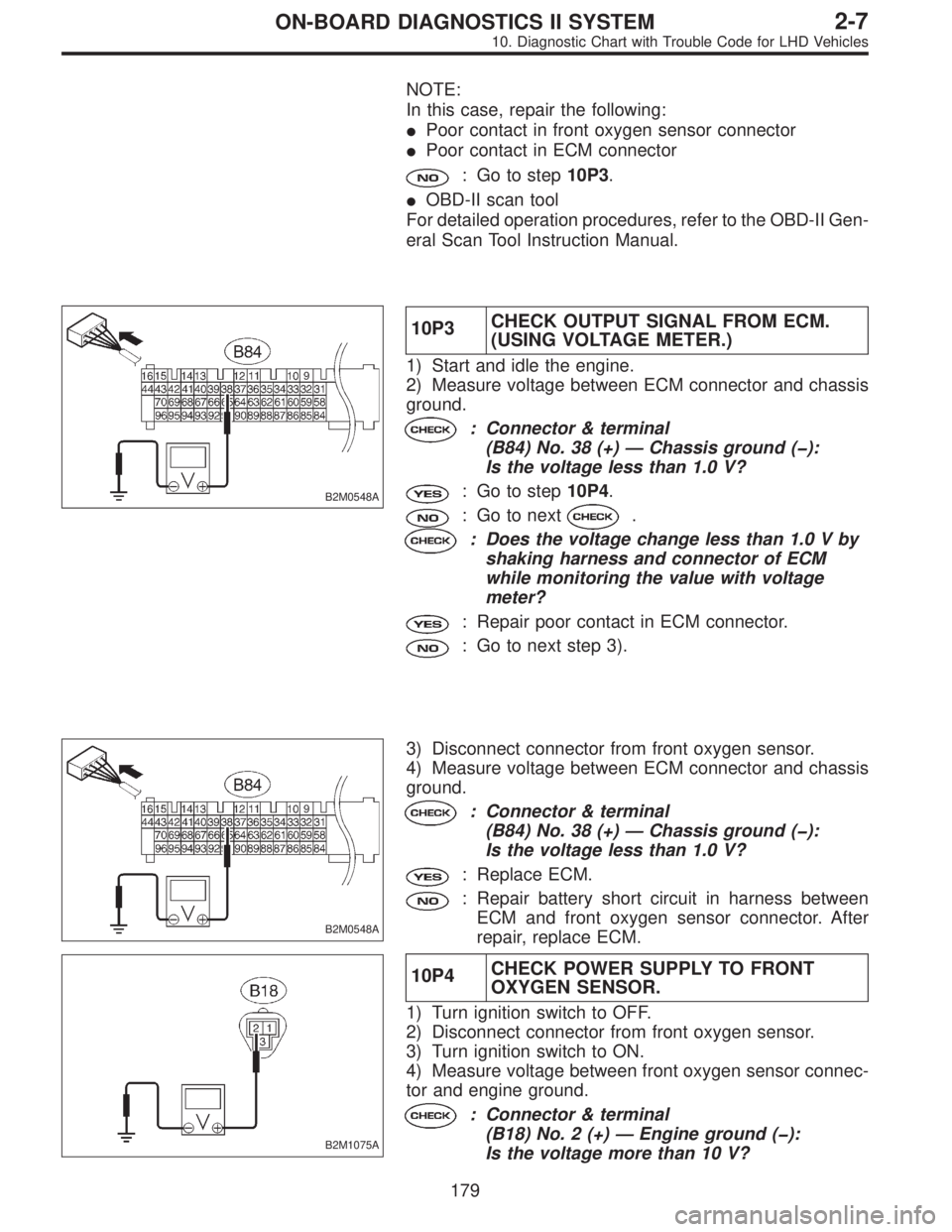
B2M0548A
10P3CHECK OUTPUT SIGNAL FROM ECM.
(USING VOLTAGE METER.)
1) Start and idle the engine.
2) Measure voltage between ECM connector and chassis
ground.
: Connector & terminal
(B84) No. 38 (+)—Chassis ground (�):
Is the voltage less than 1.0 V?
: Go to step10P4.
: Go to next.
: Does the voltage change less than 1.0 V by
shaking harness and connector of ECM
while monitoring the value with voltage
meter?
: Repair poor contact in ECM connector.
: Go to next step 3).
B2M0548A
3) Disconnect connector from front oxygen sensor.
4) Measure voltage between ECM connector and chassis
ground.
: Connector & terminal
(B84) No. 38 (+)—Chassis ground (�):
Is the voltage less than 1.0 V?
: Replace ECM.
: Repair battery short circuit in harness between
ECM and front oxygen sensor connector. After
repair, replace ECM.
B2M1075A
10P4CHECK POWER SUPPLY TO FRONT
OXYGEN SENSOR.
1) Turn ignition switch to OFF.
2) Disconnect connector from front oxygen sensor.
3) Turn ignition switch to ON.
4) Measure voltage between front oxygen sensor connec-
tor and engine ground.
: Connector & terminal
(B18) No. 2 (+)—Engine ground (�):
Is the voltage more than 10 V?
179
2-7ON-BOARD DIAGNOSTICS II SYSTEM
10. Diagnostic Chart with Trouble Code for LHD Vehicles
Page 2033 of 3342
10Q1
CHECK DTC P0130 ON DISPLAY.
: Does the Subaru select monitor or OBD-II
general scan tool indicate DTC P0130?
: Go to step10Q2.
: Go to step10Q3.
10Q2
CHECK FAILURE CAUSE OF P0130.
Perform the step 1 of DTC P0130.
: Is the failure cause of P0130 in the fuel sys-
tem?
: Check fuel system.
NOTE:
In this case, it is not necessary to inspect DTC P0136.
: Go to step10Q3.
OBD0145A
10Q3
CHECK REAR OXYGEN SENSOR DATA.
1) Turn ignition switch to OFF.
2) Connect Subaru Select Monitor or OBD-II general scan
tool to data link connector.
3) Start the engine, and turn Subaru Select Monitor or
OBD-II general scan tool switch to ON.
4) Warm-up the engine until engine coolant temperature is
above 70°C (160°F), and keep the engine speed at 2,000
rpm to 3,000 rpm for two minutes.
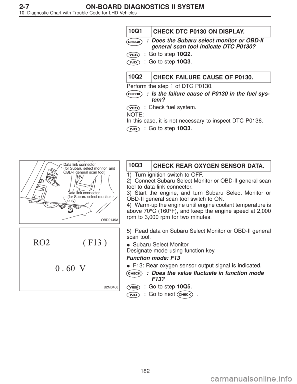
B2M0488
5) Read data on Subaru Select Monitor or OBD-II general
scan tool.
�Subaru Select Monitor
Designate mode using function key.
Function mode: F13
�F13: Rear oxygen sensor output signal is indicated.
: Does the value fluctuate in function mode
F13?
: Go to step10Q5.
: Go to next.
182
2-7ON-BOARD DIAGNOSTICS II SYSTEM
10. Diagnostic Chart with Trouble Code for LHD Vehicles
Page 2039 of 3342
NOTE:
In this case, repair the following:
�Poor contact in rear oxygen sensor connector
�Poor contact in rear oxygen sensor connecting harness
connector
�Poor contact in ECM connector
: Go to step10S3.
�OBD-II scan tool
For detailed operation procedures, refer to the OBD-II Gen-
eral Scan Tool Instruction Manual.
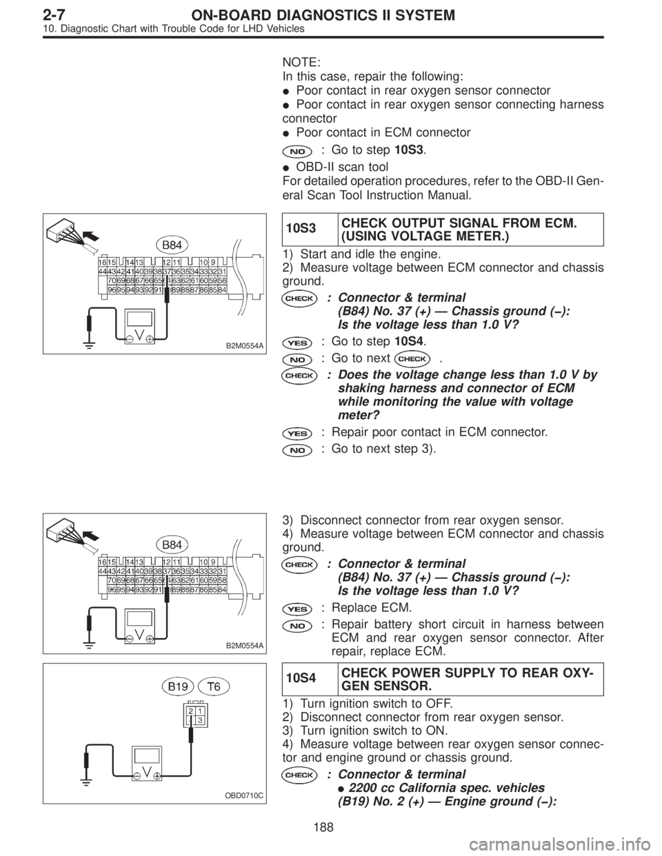
B2M0554A
10S3CHECK OUTPUT SIGNAL FROM ECM.
(USING VOLTAGE METER.)
1) Start and idle the engine.
2) Measure voltage between ECM connector and chassis
ground.
: Connector & terminal
(B84) No. 37 (+)—Chassis ground (�):
Is the voltage less than 1.0 V?
: Go to step10S4.
: Go to next.
: Does the voltage change less than 1.0 V by
shaking harness and connector of ECM
while monitoring the value with voltage
meter?
: Repair poor contact in ECM connector.
: Go to next step 3).
B2M0554A
3) Disconnect connector from rear oxygen sensor.
4) Measure voltage between ECM connector and chassis
ground.
: Connector & terminal
(B84) No. 37 (+)—Chassis ground (�):
Is the voltage less than 1.0 V?
: Replace ECM.
: Repair battery short circuit in harness between
ECM and rear oxygen sensor connector. After
repair, replace ECM.
OBD0710C
10S4CHECK POWER SUPPLY TO REAR OXY-
GEN SENSOR.
1) Turn ignition switch to OFF.
2) Disconnect connector from rear oxygen sensor.
3) Turn ignition switch to ON.
4) Measure voltage between rear oxygen sensor connec-
tor and engine ground or chassis ground.
: Connector & terminal
�2200 cc California spec. vehicles
(B19) No. 2 (+)—Engine ground (�):
188
2-7ON-BOARD DIAGNOSTICS II SYSTEM
10. Diagnostic Chart with Trouble Code for LHD Vehicles
Page 2056 of 3342
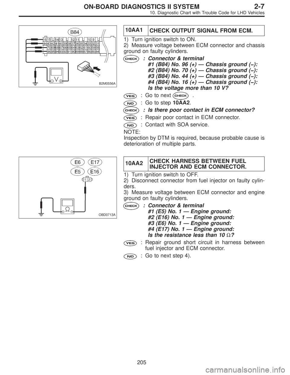
B2M0556A
10AA1
CHECK OUTPUT SIGNAL FROM ECM.
1) Turn ignition switch to ON.
2) Measure voltage between ECM connector and chassis
ground on faulty cylinders.
: Connector & terminal
#1 (B84) No. 96 (+)—Chassis ground (�):
#2 (B84) No. 70 (+)—Chassis ground (�):
#3 (B84) No. 44 (+)—Chassis ground (�):
#4 (B84) No. 16 (+)—Chassis ground (�):
Is the voltage more than 10 V?
: Go to next.
: Go to step10AA2.
: Is there poor contact in ECM connector?
: Repair poor contact in ECM connector.
: Contact with SOA service.
NOTE:
Inspection by DTM is required, because probable cause is
deterioration of multiple parts.
OBD0713A
10AA2CHECK HARNESS BETWEEN FUEL
INJECTOR AND ECM CONNECTOR.
1) Turn ignition switch to OFF.
2) Disconnect connector from fuel injector on faulty cylin-
ders.
3) Measure voltage between ECM connector and engine
ground on faulty cylinders.
: Connector & terminal
#1 (E5) No. 1—Engine ground:
#2 (E16) No. 1—Engine ground:
#3 (E6) No. 1—Engine ground:
#4 (E17) No. 1—Engine ground:
Is the resistance less than 10Ω?
: Repair ground short circuit in harness between
fuel injector and ECM connector.
: Go to next step 4).
205
2-7ON-BOARD DIAGNOSTICS II SYSTEM
10. Diagnostic Chart with Trouble Code for LHD Vehicles
Page 2060 of 3342
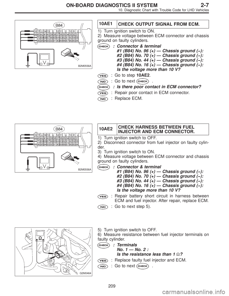
B2M0556A
10AE1
CHECK OUTPUT SIGNAL FROM ECM.
1) Turn ignition switch to ON.
2) Measure voltage between ECM connector and chassis
ground on faulty cylinders.
: Connector & terminal
#1 (B84) No. 96 (+)—Chassis ground (�):
#2 (B84) No. 70 (+)—Chassis ground (�):
#3 (B84) No. 44 (+)—Chassis ground (�):
#4 (B84) No. 16 (+)—Chassis ground (�):
Is the voltage more than 10 V?
: Go to step10AE2.
: Go to next.
: Is there poor contact in ECM connector?
: Repair poor contact in ECM connector.
: Replace ECM.
B2M0556A
10AE2CHECK HARNESS BETWEEN FUEL
INJECTOR AND ECM CONNECTOR.
1) Turn ignition switch to OFF.
2) Disconnect connector from fuel injector on faulty cylin-
der.
3) Turn ignition switch to ON.
4) Measure voltage between ECM connector and chassis
ground on faulty cylinders.
: Connector & terminal
#1 (B84) No. 96 (+)—Chassis ground (�):
#2 (B84) No. 70 (+)—Chassis ground (�):
#3 (B84) No. 44 (+)—Chassis ground (�):
#4 (B84) No. 16 (+)—Chassis ground (�):
Is the voltage more than 10 V?
: Repair battery short circuit in harness between
ECM and fuel injector. After repair, replace ECM.
: Go to next step 5).
G2M0464
5) Turn ignition switch to OFF.
6) Measure resistance between fuel injector terminals on
faulty cylinder.
: Terminals
No. 1—No.2:
Is the resistance less than 1Ω?
: Replace faulty fuel injector and ECM.
: Go to next.
209
2-7ON-BOARD DIAGNOSTICS II SYSTEM
10. Diagnostic Chart with Trouble Code for LHD Vehicles
Page 2072 of 3342
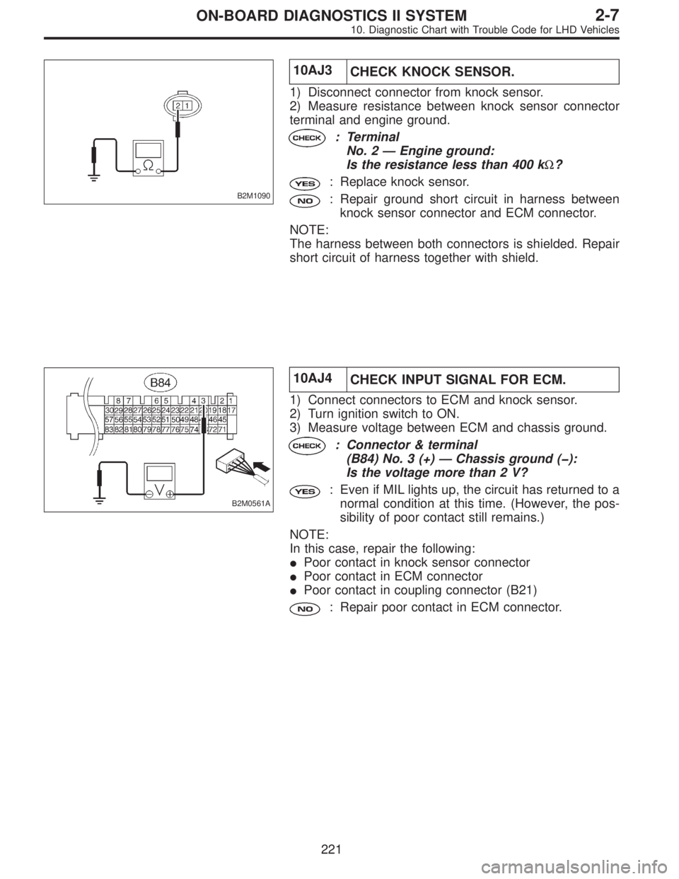
B2M1090
10AJ3
CHECK KNOCK SENSOR.
1) Disconnect connector from knock sensor.
2) Measure resistance between knock sensor connector
terminal and engine ground.
: Terminal
No. 2—Engine ground:
Is the resistance less than 400 kΩ?
: Replace knock sensor.
: Repair ground short circuit in harness between
knock sensor connector and ECM connector.
NOTE:
The harness between both connectors is shielded. Repair
short circuit of harness together with shield.
B2M0561A
10AJ4
CHECK INPUT SIGNAL FOR ECM.
1) Connect connectors to ECM and knock sensor.
2) Turn ignition switch to ON.
3) Measure voltage between ECM and chassis ground.
: Connector & terminal
(B84) No. 3 (+)—Chassis ground (�):
Is the voltage more than 2 V?
: Even if MIL lights up, the circuit has returned to a
normal condition at this time. (However, the pos-
sibility of poor contact still remains.)
NOTE:
In this case, repair the following:
�Poor contact in knock sensor connector
�Poor contact in ECM connector
�Poor contact in coupling connector (B21)
: Repair poor contact in ECM connector.
221
2-7ON-BOARD DIAGNOSTICS II SYSTEM
10. Diagnostic Chart with Trouble Code for LHD Vehicles
Page 2089 of 3342
![SUBARU LEGACY 1997 Service Repair Manual 10AP1
CHECK ENGINE/TRANSMISSION TYPE.
: Is engine/transmission type 2200 cc/MT?
: Check AT/MT identification circuit. <Ref. to 2-7
[T10DD0].>
: Go to step10AP2.
B2M0566A
10AP2
CHECK OUTPUT SIGNAL FROM SUBARU LEGACY 1997 Service Repair Manual 10AP1
CHECK ENGINE/TRANSMISSION TYPE.
: Is engine/transmission type 2200 cc/MT?
: Check AT/MT identification circuit. <Ref. to 2-7
[T10DD0].>
: Go to step10AP2.
B2M0566A
10AP2
CHECK OUTPUT SIGNAL FROM](/manual-img/17/57434/w960_57434-2088.png)
10AP1
CHECK ENGINE/TRANSMISSION TYPE.
: Is engine/transmission type 2200 cc/MT?
: Check AT/MT identification circuit.
[T10DD0].>
: Go to step10AP2.
B2M0566A
10AP2
CHECK OUTPUT SIGNAL FROM ECM.
1) Turn ignition switch to ON.
2) Measure voltage between ECM and chassis ground.
: Connector & terminal
(B84) No. 71 (+)—Chassis ground (�):
Is the voltage more than 10 V?
: Go to next.
: Go to step10AP3.
: Is there poor contact in ECM connector?
: Repair poor contact in ECM connector.
: Even if MIL lights up, the circuit has returned to a
normal condition at this time. (However, the pos-
sibility of poor contact still remains.)
NOTE:
In this case, repair the following:
�Poor contact in EGR solenoid valve connector
�Poor contact in ECM connector
�Poor contact in coupling connector (B21)
OBD0678A
10AP3CHECK HARNESS BETWEEN EGR
SOLENOID VALVE AND ECM CONNEC-
TOR.
1) Turn ignition switch to OFF.
2) Disconnect connectors from EGR solenoid valve and
ECM.
3) Measure resistance of harness between EGR solenoid
valve connector and engine ground.
: Connector & terminal
(E18) No. 2—Engine ground:
Is the resistance less than 10Ω?
: Repair ground short circuit in harness between
ECM and EGR solenoid valve connector.
: Go to next step 4).
238
2-7ON-BOARD DIAGNOSTICS II SYSTEM
10. Diagnostic Chart with Trouble Code for LHD Vehicles
Page 2100 of 3342
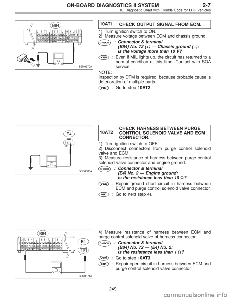
B2M0570A
10AT1
CHECK OUTPUT SIGNAL FROM ECM.
1) Turn ignition switch to ON.
2) Measure voltage between ECM and chassis ground.
: Connector & terminal
(B84) No. 72 (+)—Chassis ground (�):
Is the voltage more than 10 V?
: Even if MIL lights up, the circuit has returned to a
normal condition at this time. Contact with SOA
service.
NOTE:
Inspection by DTM is required, because probable cause is
deterioration of multiple parts.
: Go to step10AT2.
OBD0680A
10AT2CHECK HARNESS BETWEEN PURGE
CONTROL SOLENOID VALVE AND ECM
CONNECTOR.
1) Turn ignition switch to OFF.
2) Disconnect connectors from purge control solenoid
valve and ECM.
3) Measure resistance of harness between purge control
solenoid valve connector and engine ground.
: Connector & terminal
(E4) No. 2—Engine ground:
Is the resistance less than 10Ω?
: Repair ground short circuit in harness between
ECM and purge control solenoid valve connector.
: Go to next step 4).
B2M0571A
4) Measure resistance of harness between ECM and
purge control solenoid valve of harness connector.
: Connector & terminal
(B84) No. 72—(E4) No. 2:
Is the resistance less than 1Ω?
: Go to step10AT3.
: Repair open circuit in harness between ECM and
purge control solenoid valve connector.
249
2-7ON-BOARD DIAGNOSTICS II SYSTEM
10. Diagnostic Chart with Trouble Code for LHD Vehicles