Page 1914 of 3342

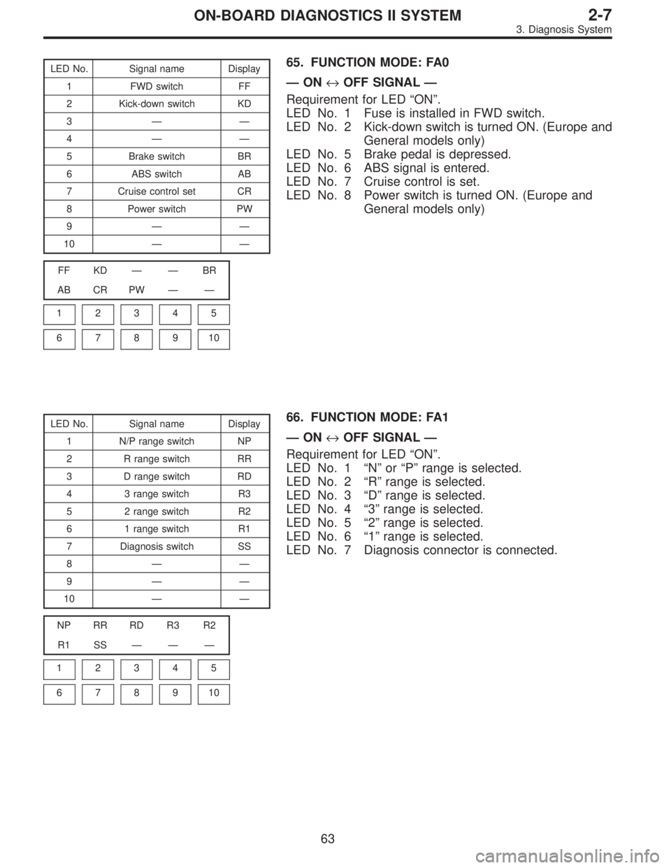
LED No. Signal name Display
1 FWD switch FF
2 Kick-down switch KD
3——
4——
5 Brake switch BR
6 ABS switch AB
7 Cruise control set CR
8 Power switch PW
9——
10——
FF KD——BR
AB CR PW——
1
2345
678910
65. FUNCTION MODE: FA0
—ON↔OFF SIGNAL—
Requirement for LED“ON”.
LED No. 1 Fuse is installed in FWD switch.
LED No. 2 Kick-down switch is turned ON. (Europe and
General models only)
LED No. 5 Brake pedal is depressed.
LED No. 6 ABS signal is entered.
LED No. 7 Cruise control is set.
LED No. 8 Power switch is turned ON. (Europe and
General models only)
LED No. Signal name Display
1 N/P range switch NP
2 R range switch RR
3 D range switch RD
4 3 range switch R3
5 2 range switch R2
6 1 range switch R1
7 Diagnosis switch SS
8——
9——
10——
NP RR RD R3 R2
R1 SS———
1
2345
678910
66. FUNCTION MODE: FA1
—ON↔OFF SIGNAL—
Requirement for LED“ON”.
LED No. 1“N”or“P”range is selected.
LED No. 2“R”range is selected.
LED No. 3“D”range is selected.
LED No. 4“3”range is selected.
LED No. 5“2”range is selected.
LED No. 6“1”range is selected.
LED No. 7 Diagnosis connector is connected.
63
2-7ON-BOARD DIAGNOSTICS II SYSTEM
3. Diagnosis System
Page 1932 of 3342
ContentConnector
No.Terminal
No.Signal (V)
Note
Ignition SW ON
(Engine OFF)Engine ON (Idling)
AT diagnosis input signal B84 80Less than 1)More
than 4Less than 1)More
than 4Waveform
GND (sensors) B84 20 0 0—
GND (injectors) B8469
00—
95
GND (ignition system) B84 94 0 0—
GND (power supply) B8419
00—
46
GND (control systems) B8417
00—
18
GND (oxygen sensor
heater)B84 42 0 0—
2. ENGINE CONDITION DATA
Content Model Specified data
Mass air flow2200 cc1.7—3.3 (g/sec): Idling
7.1—14.2 (g/sec): 2,500 rpm racing
2500 cc2.2—4.2 (g/sec): Idling
8.6—14.5 (g/sec): 2,500 rpm racing
Engine load2200 cc1.6—2.9 (%): Idling
6.4—12.8 (%): 2,500 rpm racing
2500 cc1.9—3.5 (%): Idling
7.2—12.1 (%): 2,500 rpm racing
Measuring condition:
�After warm-up the engine.
�Gear position is in“N”or“P”position.
�A/C is turned OFF.
�All accessory switches are turned OFF.
81
2-7ON-BOARD DIAGNOSTICS II SYSTEM
5. Specified Data
Page 1940 of 3342

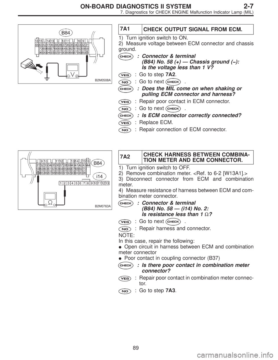
B2M0508A
7A1
CHECK OUTPUT SIGNAL FROM ECM.
1) Turn ignition switch to ON.
2) Measure voltage between ECM connector and chassis
ground.
: Connector & terminal
(B84) No. 58 (+) — Chassis ground (�):
Is the voltage less than 1 V?
: Go to step7A2.
: Go to next.
: Does the MIL come on when shaking or
pulling ECM connector and harness?
: Repair poor contact in ECM connector.
: Go to next.
: Is ECM connector correctly connected?
: Replace ECM.
: Repair connection of ECM connector.
B2M0763A
7A2CHECK HARNESS BETWEEN COMBINA-
TION METER AND ECM CONNECTOR.
1) Turn ignition switch to OFF.
2) Remove combination meter.
3) Disconnect connector from ECM and combination
meter.
4) Measure resistance of harness between ECM and com-
bination meter connector.
: Connector & terminal
(B84) No. 58 — (i14) No. 2:
Is resistance less than 1Ω?
: Go to next.
: Repair harness and connector.
NOTE:
In this case, repair the following:
�Open circuit in harness between ECM and combination
meter connector
�Poor contact in coupling connector (B37)
: Is there poor contact in combination meter
connector?
: Repair poor contact in combination meter connec-
tor.
: Go to step7A3.
89
2-7ON-BOARD DIAGNOSTICS II SYSTEM
7. Diagnostics for CHECK ENGINE Malfunction Indicator Lamp (MIL)
Page 1945 of 3342

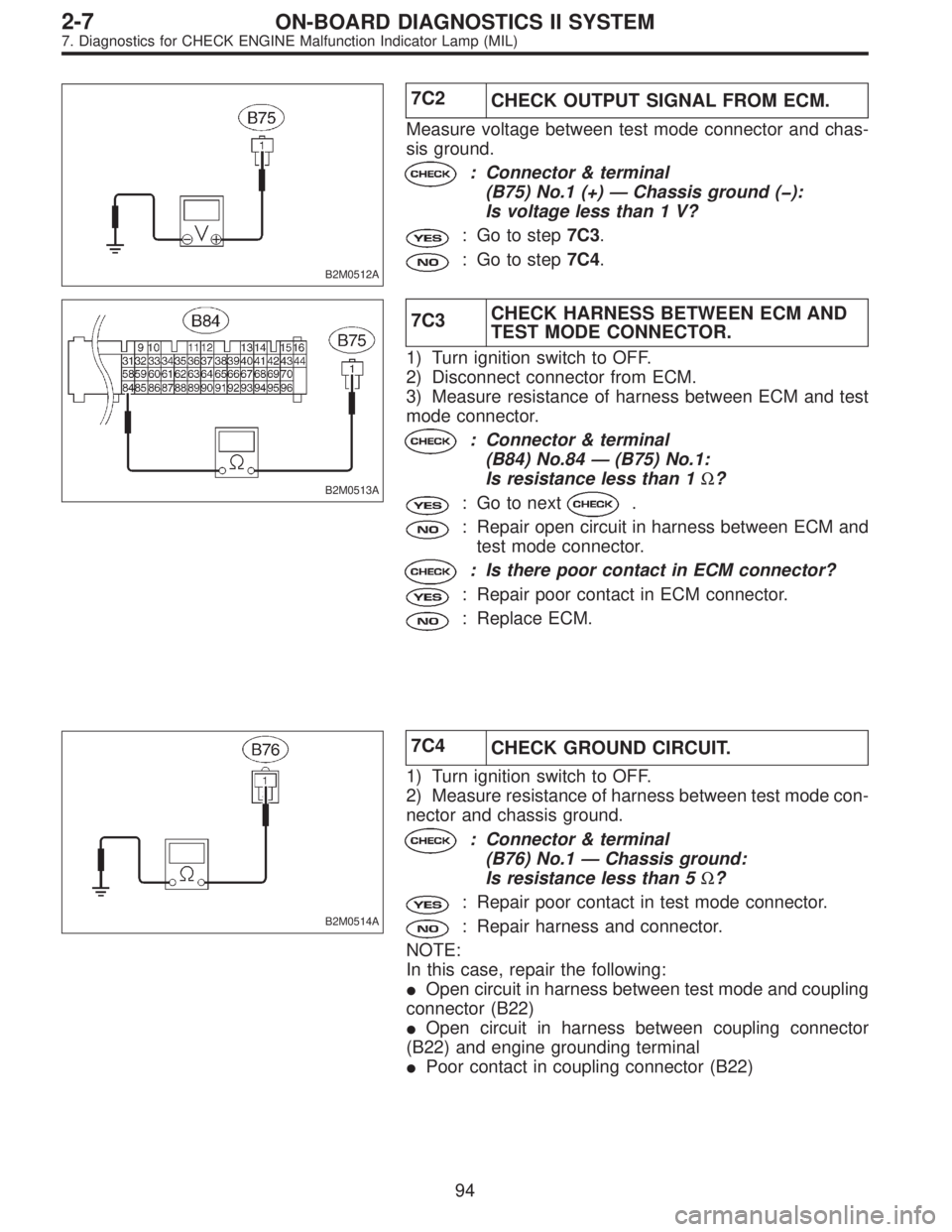
B2M0512A
7C2
CHECK OUTPUT SIGNAL FROM ECM.
Measure voltage between test mode connector and chas-
sis ground.
: Connector & terminal
(B75) No.1 (+)—Chassis ground (�):
Is voltage less than 1 V?
: Go to step7C3.
: Go to step7C4.
B2M0513A
7C3CHECK HARNESS BETWEEN ECM AND
TEST MODE CONNECTOR.
1) Turn ignition switch to OFF.
2) Disconnect connector from ECM.
3) Measure resistance of harness between ECM and test
mode connector.
: Connector & terminal
(B84) No.84—(B75) No.1:
Is resistance less than 1Ω?
: Go to next.
: Repair open circuit in harness between ECM and
test mode connector.
: Is there poor contact in ECM connector?
: Repair poor contact in ECM connector.
: Replace ECM.
B2M0514A
7C4
CHECK GROUND CIRCUIT.
1) Turn ignition switch to OFF.
2) Measure resistance of harness between test mode con-
nector and chassis ground.
: Connector & terminal
(B76) No.1—Chassis ground:
Is resistance less than 5Ω?
: Repair poor contact in test mode connector.
: Repair harness and connector.
NOTE:
In this case, repair the following:
�Open circuit in harness between test mode and coupling
connector (B22)
�Open circuit in harness between coupling connector
(B22) and engine grounding terminal
�Poor contact in coupling connector (B22)
94
2-7ON-BOARD DIAGNOSTICS II SYSTEM
7. Diagnostics for CHECK ENGINE Malfunction Indicator Lamp (MIL)
Page 1948 of 3342
B: STARTER MOTOR CIRCUIT
WIRING DIAGRAM:
B2M1047
CAUTION:
After repair or replacement of faulty parts, conduct
CLEAR MEMORY and INSPECTION MODES.
OBD0724
8B1CHECK INPUT SIGNAL FOR STARTER
MOTOR.
1) Turn ignition switch to OFF.
2) Disconnect connector from starter motor.
3) Turn ignition switch to ST.
97
2-7ON-BOARD DIAGNOSTICS II SYSTEM
8. Diagnostics for Engine Starting Failure
Page 1961 of 3342
B2M1051A
B2M0224A
8D5
CHECK INPUT SIGNAL FOR IGNITOR.
Check if voltage varies synchronously with engine speed
when cranking, while monitoring voltage between ignitor
connector and engine ground.
: Connector & terminal:
(B13) No. 1 (+)—Engine ground (�):
Is the voltage more than 10 V?
: Go to next.
: Replace ignitor.
: Connector & terminal:
(B13) No. 2 (+)—Engine ground (�):
Is the voltage more than 10 V?
: Go to step8D6.
: Replace ignitor.
OBD0128A
8D6CHECK HARNESS OF IGNITOR GROUND
CIRCUIT.
1) Turn ignition switch to OFF.
2) Measure resistance between ignitor and engine ground.
: Connector & terminal
(B13) No. 3—Engine ground:
Is the resistance less than 5Ω?
: Go to step8D7.
: Repair open circuit in harness between ignitor
connector and engine grounding terminal.
11 0
2-7ON-BOARD DIAGNOSTICS II SYSTEM
8. Diagnostics for Engine Starting Failure
Page 1974 of 3342
![SUBARU LEGACY 1997 Service Repair Manual 9. General Diagnostic Table
A: GENERAL DIAGNOSTICS TABLE WITH
NONCONFORMITY SYMPTOM FOR ENGINE
NOTE:
Malfunction of parts other than those listed is also possible.
<Ref. to 2-3 [K100], 2-3b [K100].>
S SUBARU LEGACY 1997 Service Repair Manual 9. General Diagnostic Table
A: GENERAL DIAGNOSTICS TABLE WITH
NONCONFORMITY SYMPTOM FOR ENGINE
NOTE:
Malfunction of parts other than those listed is also possible.
<Ref. to 2-3 [K100], 2-3b [K100].>
S](/manual-img/17/57434/w960_57434-1973.png)
9. General Diagnostic Table
A: GENERAL DIAGNOSTICS TABLE WITH
NONCONFORMITY SYMPTOM FOR ENGINE
NOTE:
Malfunction of parts other than those listed is also possible.
Symptom Problem parts
1. Engine stalls during idling.1) Idle air control solenoid valve
2) Mass air flow sensor
3) Ignition parts (*1)
4) Engine coolant temperature sensor (*2)
5) Crankshaft position sensor (*3)
6) Camshaft position sensor (*3)
7) EGR valve
8) Fuel injection parts (*4)
2. Rough idling1) Idle air control solenoid valve
2) Mass air flow sensor
3) Engine coolant temperature sensor (*2)
4) Ignition parts (*1)
5) Air intake system (*5)
6) Fuel injection parts (*4)
7) Throttle position sensor
8) Crankshaft position sensor (*3)
9) Camshaft position sensor (*3)
10) EGR valve
11) Oxygen sensor
12) Fuel pump and fuel pump relay
3. Engine does not return to idle.1) Idle air control solenoid valve
2) Engine coolant temperature sensor
3) Accelerator cable (*6)
4) Throttle position sensor
5) Mass air flow sensor
4. Poor acceleration1) Mass air flow sensor
2) Throttle position sensor
3) Fuel injection parts (*4)
4) Fuel pump and fuel pump relay
5) Engine coolant temperature sensor (*2)
6) Crankshaft position sensor (*3)
7) Camshaft position sensor (*3)
8) A/C switch and A/C cut relay
9) Engine torque control signal circuit
10) Ignition parts (*1)
5. Engine stalls or engine sags or hesitates at
acceleration.1) Mass air flow sensor
2) Engine coolant temperature sensor (*2)
3) Crankshaft position sensor (*3)
4) Camshaft position sensor (*3)
5) Purge control solenoid valve
6) EGR valve
7) Fuel injection parts (*4)
8) Throttle position sensor
9) Fuel pump and fuel pump relay
6. Surge1) Mass air flow sensor
2) Engine coolant temperature sensor (*2)
3) Crankshaft position sensor (*3)
4) Camshaft position sensor (*3)
5) EGR valve
6) Fuel injection parts (*4)
7) Throttle position sensor
8) Fuel pump and fuel pump relay
123
2-7ON-BOARD DIAGNOSTICS II SYSTEM
9. General Diagnostic Table
Page 1979 of 3342

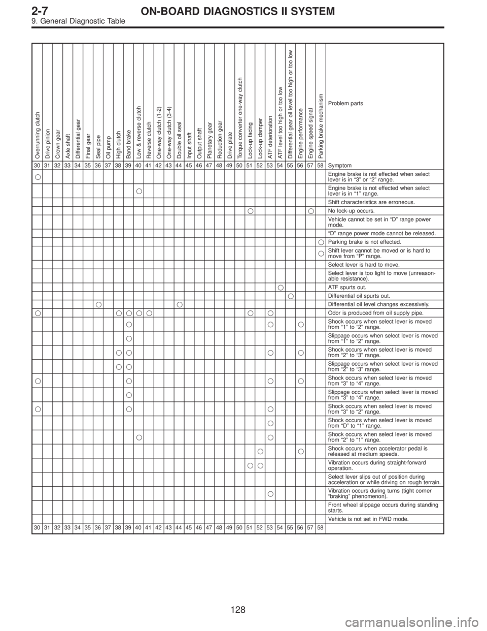
Overrunning clutch
Drive pinion
Crown gear
Axle shaft
Differential gear
Final gear
Seal pipe
Oil pump
High clutch
Band brake
Low & reverse clutch
Reverse clutch
One-way clutch (1-2)
One-way clutch (3-4)
Double oil seal
Input shaft
Output shaft
Planetary gear
Reduction gear
Drive plate
Torque converter one-way clutch
Lock-up facing
Lock-up damper
ATF deterioration
ATF level too high or too low
Differential gear oil level too high or too low
Engine performance
Engine speed signal
Parking brake mechanism
Problem parts
30 31 32 33 34 35 36 37 38 39 40 41 42 43 44 45 46 47 48 49 50 51 52 53 54 55 56 57 58 Symptom
�Engine brake is not effected when select
lever is in“3”or“2”range.
�Engine brake is not effected when select
lever is in“1”range.
Shift characteristics are erroneous.
��No lock-up occurs.
Vehicle cannot be set in“D”range power
mode.
“D”range power mode cannot be released.
�Parking brake is not effected.
�Shift lever cannot be moved or is hard to
move from“P”range.
Select lever is hard to move.
Select lever is too light to move (unreason-
able resistance).
�ATF spurts out.
�Differential oil spurts out.
��Differential oil level changes excessively.
� ���� � �Odor is produced from oil supply pipe.
���Shock occurs when select lever is moved
from“1”to“2”range.
�Slippage occurs when select lever is moved
from“1”to“2”range.
�� � �Shock occurs when select lever is moved
from“2”to“3”range.
��Slippage occurs when select lever is moved
from“2”to“3”range.
�� ��Shock occurs when select lever is moved
from“3”to“4”range.
�Slippage occurs when select lever is moved
from“3”to“4”range.
�� �Shock occurs when select lever is moved
from“3”to“2”range.
�Shock occurs when select lever is moved
from“D”to“1”range.
��Shock occurs when select lever is moved
from“2”to“1”range.
��Shock occurs when accelerator pedal is
released at medium speeds.
��Vibration occurs during straight-forward
operation.
Select lever slips out of position during
acceleration or while driving on rough terrain.
�Vibration occurs during turns (tight corner
“braking”phenomenon).
Front wheel slippage occurs during standing
starts.
Vehicle is not set in FWD mode.
30 31 32 33 34 35 36 37 38 39 40 41 42 43 44 45 46 47 48 49 50 51 52 53 54 55 56 57 58
128
2-7ON-BOARD DIAGNOSTICS II SYSTEM
9. General Diagnostic Table