Page 149 of 3342
4-4d
[T1onno]
BRAKES
[ABS
5
.3i
TYPE]
10
.
Diagnostics
Chart
withSelect
Monitor
D
"
NEW
29
EITHER
.
SS
(FBI)
SOFT
84M0952
J
M
:
TROUBLE
CODE
29
EITHER
.
SS
SOFT
-
ABNORMAL
ABS
SENSOR
SIGNAL
(ANY
ONE
OF
FOUR)
-
DIAGNOSIS
:
"
Faulty
ABS
sensor
signal
(noise,
irregular
signal,
etc
.)
"
Faulty
tone
wheel
"
Wheels
turning
freely
for
a
long
time
TROUBLE
SYMPTOM
:
9
ABS
does
not
operate
.
WIRING
DIAGRAM
:
F19
ABS
control
module
and
hydraulic
control
unit
OUTBACK
withsteproof
model
(2D(E)(~D
QD
rll~9
No"111
100
--------
Front
ABS
F
V
----------
;
sensorl-H
LjJF
---
----------
Front
ABS
Twisted
-----
sensor
RH
wire
Ft
Pt
OO
RearABS
--~
sensor
LH
Twisted
wire
Rear
ABS
41
4
.
sensor
RH
P8
r----------------
I
OUTBACK
with
steproof
model
IIII
O~
I
RearABS
sensorLH
j
~
Rear
ABS
j
sensor
RH
I
~
I
L---------------J
Ft
8100
1121
3
1
10
45
78
f49
123456789101112131415
16171819
20
2122
23
2425
26
2728293031
B4M1238
132
Page 151 of 3342
![SUBARU LEGACY 1997 Service Repair Manual
4-4d
[rionns1
BRAKES
[ABS
5
.31
TYPE]
10
.
Diagnostics
Chart
withSelect
Monitor
G4M0700
I
G4M0701
I
1
101111116
I
CHECK
INSTALLATION
OF
TONE
WHEEL
.
Tightening
torque
:
13
±
3
N~m
(1.3
f
0
.3
k SUBARU LEGACY 1997 Service Repair Manual
4-4d
[rionns1
BRAKES
[ABS
5
.31
TYPE]
10
.
Diagnostics
Chart
withSelect
Monitor
G4M0700
I
G4M0701
I
1
101111116
I
CHECK
INSTALLATION
OF
TONE
WHEEL
.
Tightening
torque
:
13
±
3
N~m
(1.3
f
0
.3
k](/manual-img/17/57434/w960_57434-150.png)
4-4d
[rionns1
BRAKES
[ABS
5
.31
TYPE]
10
.
Diagnostics
Chart
withSelect
Monitor
G4M0700
I
G4M0701
I
1
101111116
I
CHECK
INSTALLATION
OF
TONE
WHEEL
.
Tightening
torque
:
13
±
3
N~m
(1.3
f
0
.3
kg-m,
9
±
2
.2
ft-Ib)
CHECK
:
Are
thetone
wheel
installation
bolts
tight-
ened
securely?
,rES
:
Go
to
step
10M7
.
No
:
Tightentone
wheel
installation
bolts
securely
.
CHECK
ABS
SENSOR
GAP
.
Measure
tone
wheel
to
pole
piece
gap
over
entire
perim-
eterof
the
wheel
.
CHECK
:
Is
the
gap
within
the
specifications
shown
in
the
following
fable?
Front
wheel
Rear
wheel
Specifications
0
.9
-
1
.4
mm
(0
.035
-
0
.055
in)
0
.7
-
1
.2
mm
(0
.028
-
0
.047
in)
Go
tostep
10M8
.
No
:
Adjustthe
gap
.
NOTE
:
Adjustthe
gap
using
spacer
(Part
No
.
26755AA000)
.
If
spacers
cannot
correct
the
gap,
replace
worn
sensor
or
worn
tone
wheel
.
1111011111118
1
CHECK
OSCILLOSCOPE
.
I
i
CHECK
:
Is
an
oscilloscope
available?
Go
to
step
10M9
.
No
:
Go
to
step
10M10
.
10M9
CHECK
ABS
SENSOR
SIGNAL
.
1)
Raise
all
four
wheels
of
ground
.
2)
Turn
ignition
switch
OFF
.
3)
Connect
the
oscilloscope
to
the
connector
(F1)
or
con
nector
(B100)
in
accordance
with
trouble
code
.
4)
Turn
ignition
switch
ON
.
134
Sensor
gap
Sensor
gap
Page 163 of 3342
![SUBARU LEGACY 1997 Service Repair Manual
BRAKES
[ABS
5
.3i
TYPE]
[T10V5]4-4d
10
.
Diagnostics
Chart
with
Select
Monitor
a
112131415161718
01112131415
11611711811912
1
23
24
2526
71
28
1
2130
1
31
1
1
La
-_
B4M
1243A
1
110111
CHECK
GROU SUBARU LEGACY 1997 Service Repair Manual
BRAKES
[ABS
5
.3i
TYPE]
[T10V5]4-4d
10
.
Diagnostics
Chart
with
Select
Monitor
a
112131415161718
01112131415
11611711811912
1
23
24
2526
71
28
1
2130
1
31
1
1
La
-_
B4M
1243A
1
110111
CHECK
GROU](/manual-img/17/57434/w960_57434-162.png)
BRAKES
[ABS
5
.3i
TYPE]
[T10V5]4-4d
10
.
Diagnostics
Chart
with
Select
Monitor
a
112131415161718
01112131415
11611711811912
1
23
24
2526
71
28
1
2130
1
31
1
1
La
-_
B4M
1243A
1
110111
CHECK
GROUND
CIRCUIT
OF
ABSCM&H/U
.
1)
Turn
ignition
switch
to
OFF
.
2)
Disconnect
connector
from
ABSCM&H/U
.
3)
Measure
resistance
between
ABSCM&H/U
and
chassis
ground
.
Connector
&
terminal
(F49)
No
.
23
-
Chassis
ground
:
CHECK
:
Is
the
resistance
less
than0
.5
S2?
YES
:
Go
to
step
10V2
.
No
:
Repair
ABSCM&H/U
ground
harness
.
CHECK
POOR
CONTACT
IN
CONNECTORS
.
CHECK
:
Is
there
poor
contact
in
connectors
between
battery,
ignition
switch
and
ABSCM&HIU?
<
Ref
.
to
FOREWORD
[T3C1]
.*10
>
Repair
connector
.
No
:
Go
to
step
10V3
.
10V3
CHECK
SOURCES
OF
SIGNAL
NOISE
.
CHECK
:
Is
thecar
telephone
orthe
wireless
transmit-
ter
properly
installed?
vES
:
Go
to
step
110114
.
No
:
Properly
install
the
car
telephone
or
the
wireless
transmitter
.
1
110114
I
CHECK
SOURCES
OF
SIGNAL
NOISE
.
I
CHECK
;
Are
noise
sources
(such
as
an
antenna)
installed
near
the
sensorharness?
.rES
:
Install
the
noise
sources
apart
from
the
sensor
harness
.
No
:
Go
to
step
10V5
.
10V5
CHECK
ABSCM&H/U
.
1)
Turn
ignition
switch
to
OFF
.
2)
Connect
all
connectors
.
3)
Erase
the
memory
.
4)
Perform
inspection
mode
.
5)
Read
outthe
trouble
code
.
CHECK
:
Is
the
same
trouble
codeas
in
the
current
diagnosis
still
being
output?
Replace
ABSCM&H/U
.
No
:
Go
to
step
10V6
.
147
Page 499 of 3342
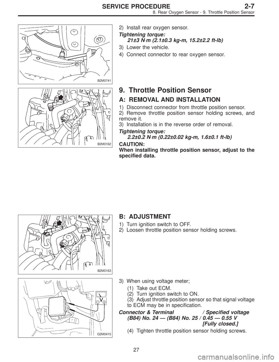
B2M0741
2) Install rear oxygen sensor.
Tightening torque:
21±3 N⋅m (2.1±0.3 kg-m, 15.2±2.2 ft-lb)
3) Lower the vehicle.
4) Connect connector to rear oxygen sensor.
B2M0162
9. Throttle Position Sensor
A: REMOVAL AND INSTALLATION
1) Disconnect connector from throttle position sensor.
2) Remove throttle position sensor holding screws, and
remove it.
3) Installation is in the reverse order of removal.
Tightening torque:
2.2±0.2 N⋅m (0.22±0.02 kg-m, 1.6±0.1 ft-lb)
CAUTION:
When installing throttle position sensor, adjust to the
specified data.
B2M0163
B: ADJUSTMENT
1) Turn ignition switch to OFF.
2) Loosen throttle position sensor holding screws.
G2M0415
3) When using voltage meter;
(1) Take out ECM.
(2) Turn ignition switch to ON.
(3) Adjust throttle position sensor so that signal voltage
to ECM may be in specification.
Connector & Terminal / Specified voltage
(B84) No. 24 — (B84) No. 25 / 0.45 — 0.55 V
[Fully closed.]
(4) Tighten throttle position sensor holding screws.
27
2-7SERVICE PROCEDURE
8. Rear Oxygen Sensor - 9. Throttle Position Sensor
Page 500 of 3342
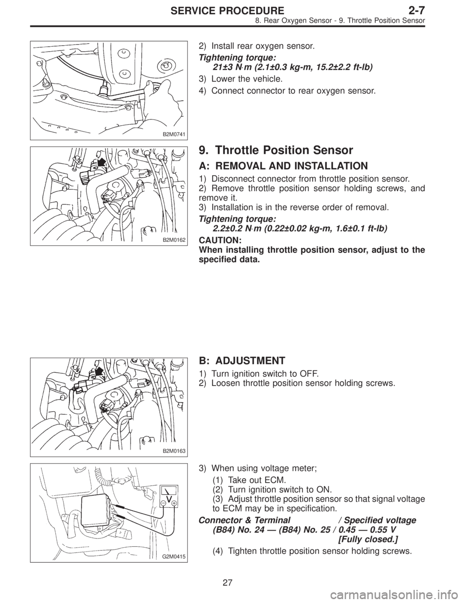
B2M0741
2) Install rear oxygen sensor.
Tightening torque:
21±3 N⋅m (2.1±0.3 kg-m, 15.2±2.2 ft-lb)
3) Lower the vehicle.
4) Connect connector to rear oxygen sensor.
B2M0162
9. Throttle Position Sensor
A: REMOVAL AND INSTALLATION
1) Disconnect connector from throttle position sensor.
2) Remove throttle position sensor holding screws, and
remove it.
3) Installation is in the reverse order of removal.
Tightening torque:
2.2±0.2 N⋅m (0.22±0.02 kg-m, 1.6±0.1 ft-lb)
CAUTION:
When installing throttle position sensor, adjust to the
specified data.
B2M0163
B: ADJUSTMENT
1) Turn ignition switch to OFF.
2) Loosen throttle position sensor holding screws.
G2M0415
3) When using voltage meter;
(1) Take out ECM.
(2) Turn ignition switch to ON.
(3) Adjust throttle position sensor so that signal voltage
to ECM may be in specification.
Connector & Terminal / Specified voltage
(B84) No. 24 — (B84) No. 25 / 0.45 — 0.55 V
[Fully closed.]
(4) Tighten throttle position sensor holding screws.
27
2-7SERVICE PROCEDURE
8. Rear Oxygen Sensor - 9. Throttle Position Sensor
Page 734 of 3342
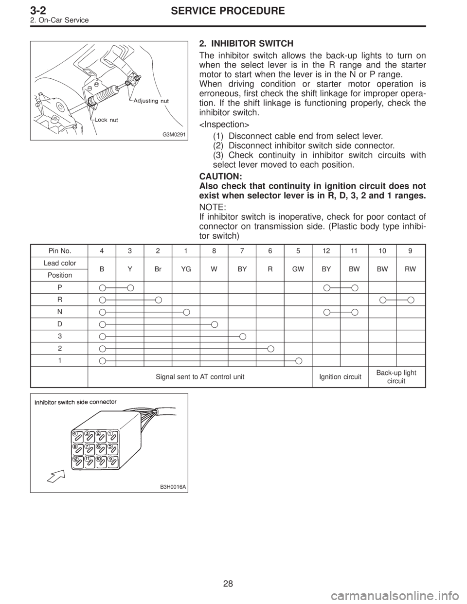
G3M0291
2. INHIBITOR SWITCH
The inhibitor switch allows the back-up lights to turn on
when the select lever is in the R range and the starter
motor to start when the lever is in the N or P range.
When driving condition or starter motor operation is
erroneous, first check the shift linkage for improper opera-
tion. If the shift linkage is functioning properly, check the
inhibitor switch.
(1) Disconnect cable end from select lever.
(2) Disconnect inhibitor switch side connector.
(3) Check continuity in inhibitor switch circuits with
select lever moved to each position.
CAUTION:
Also check that continuity in ignition circuit does not
exist when selector lever is in R, D, 3, 2 and 1 ranges.
NOTE:
If inhibitor switch is inoperative, check for poor contact of
connector on transmission side. (Plastic body type inhibi-
tor switch)
PinNo. 432187651211109
Lead color
B Y Br YG W BY R GW BY BW BW RW
Position
P��
��
R����
N����
D��
3��
2��
1��
Signal sent to AT control unit Ignition circuitBack-up light
circuit
B3H0016A
28
3-2SERVICE PROCEDURE
2. On-Car Service
Page 834 of 3342
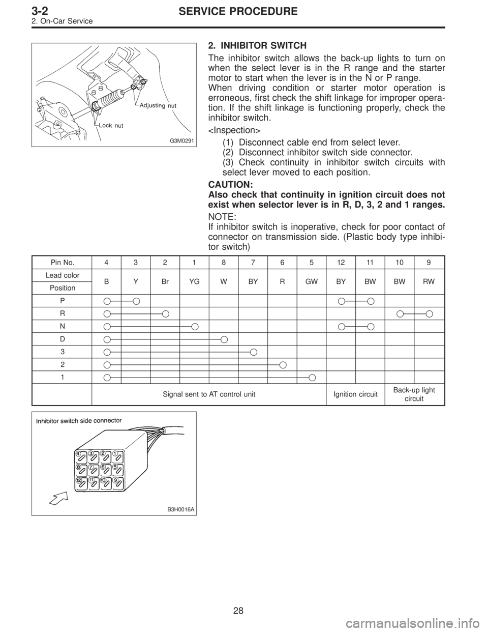
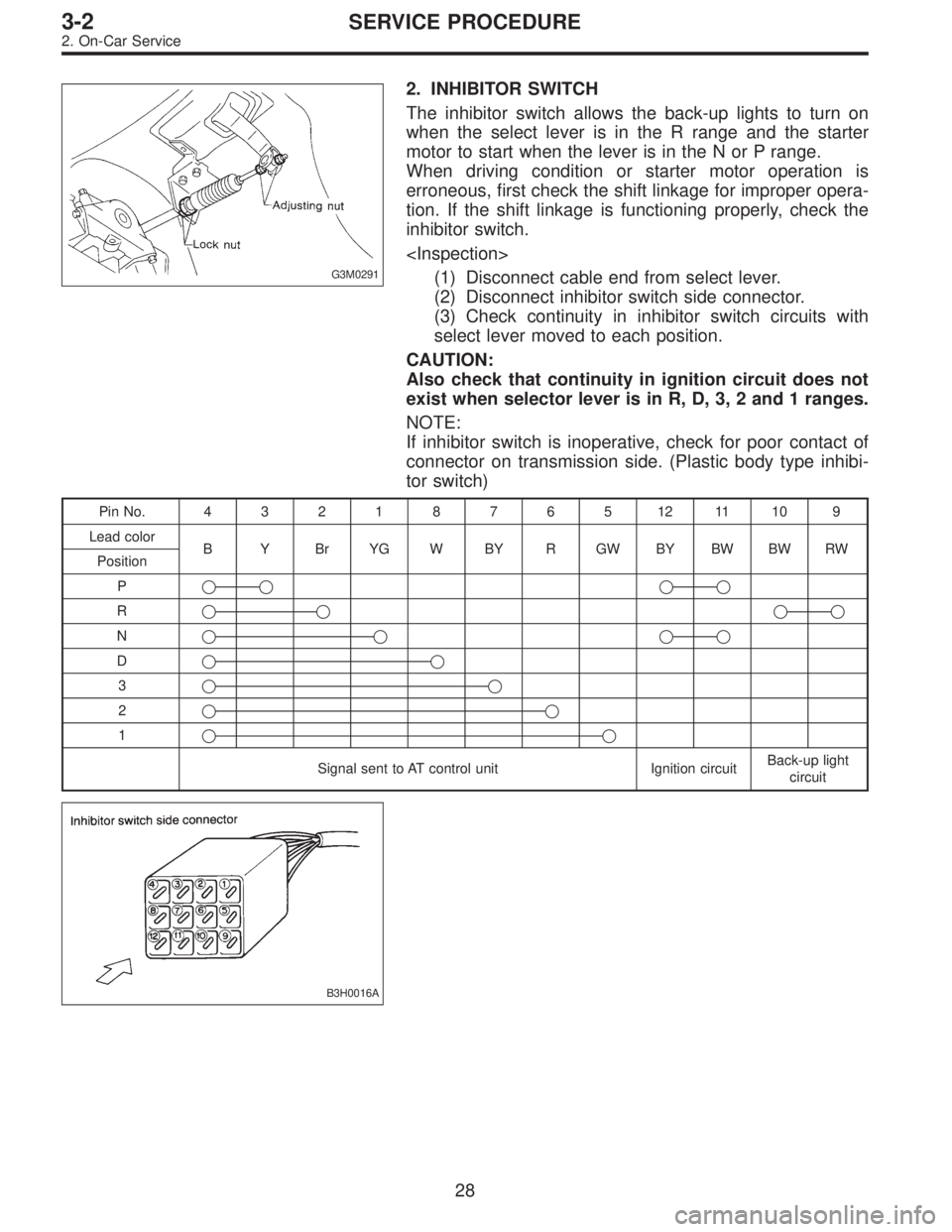
G3M0291
2. INHIBITOR SWITCH
The inhibitor switch allows the back-up lights to turn on
when the select lever is in the R range and the starter
motor to start when the lever is in the N or P range.
When driving condition or starter motor operation is
erroneous, first check the shift linkage for improper opera-
tion. If the shift linkage is functioning properly, check the
inhibitor switch.
(1) Disconnect cable end from select lever.
(2) Disconnect inhibitor switch side connector.
(3) Check continuity in inhibitor switch circuits with
select lever moved to each position.
CAUTION:
Also check that continuity in ignition circuit does not
exist when selector lever is in R, D, 3, 2 and 1 ranges.
NOTE:
If inhibitor switch is inoperative, check for poor contact of
connector on transmission side. (Plastic body type inhibi-
tor switch)
PinNo. 432187651211109
Lead color
B Y Br YG W BY R GW BY BW BW RW
Position
P��
��
R����
N����
D��
3��
2��
1��
Signal sent to AT control unit Ignition circuitBack-up light
circuit
B3H0016A
28
3-2SERVICE PROCEDURE
2. On-Car Service
Page 934 of 3342
G3M0291
2. INHIBITOR SWITCH
The inhibitor switch allows the back-up lights to turn on
when the select lever is in the R range and the starter
motor to start when the lever is in the N or P range.
When driving condition or starter motor operation is
erroneous, first check the shift linkage for improper opera-
tion. If the shift linkage is functioning properly, check the
inhibitor switch.
(1) Disconnect cable end from select lever.
(2) Disconnect inhibitor switch side connector.
(3) Check continuity in inhibitor switch circuits with
select lever moved to each position.
CAUTION:
Also check that continuity in ignition circuit does not
exist when selector lever is in R, D, 3, 2 and 1 ranges.
NOTE:
If inhibitor switch is inoperative, check for poor contact of
connector on transmission side. (Plastic body type inhibi-
tor switch)
PinNo. 432187651211109
Lead color
B Y Br YG W BY R GW BY BW BW RW
Position
P��
��
R����
N����
D��
3��
2��
1��
Signal sent to AT control unit Ignition circuitBack-up light
circuit
B3H0016A
28
3-2SERVICE PROCEDURE
2. On-Car Service