Page 1841 of 3342
G: DIAGNOSTICS PROCEDURE FOR DOOR
SWITCH SIGNAL
1. Check door switch input signal for security
control module.
Not OK
�OK
Go to next step on basic diagnostics procedure.
2. Check door switch.
OK
�Not OK
Replace door switch.
Repair or replace wiring harness between door
switch and security control module.
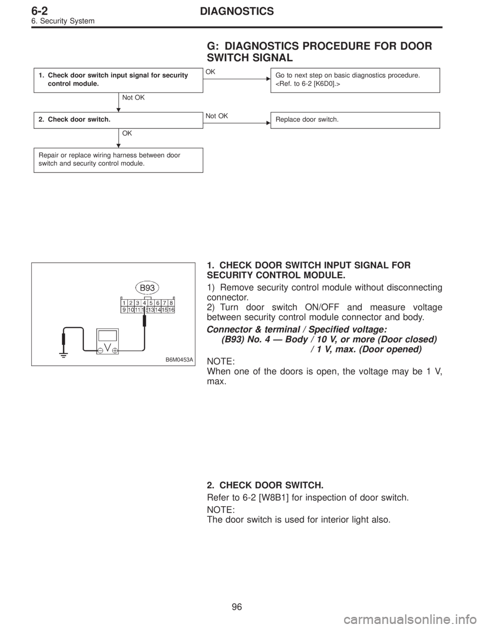
B6M0453A
1. CHECK DOOR SWITCH INPUT SIGNAL FOR
SECURITY CONTROL MODULE.
1) Remove security control module without disconnecting
connector.
2) Turn door switch ON/OFF and measure voltage
between security control module connector and body.
Connector & terminal / Specified voltage:
(B93) No. 4—Body / 10 V, or more (Door closed)
/ 1 V, max. (Door opened)
NOTE:
When one of the doors is open, the voltage may be 1 V,
max.
2. CHECK DOOR SWITCH.
Refer to 6-2 [W8B1] for inspection of door switch.
NOTE:
The door switch is used for interior light also.
�
�
96
6-2DIAGNOSTICS
6. Security System
Page 1842 of 3342
H: DIAGNOSTICS PROCEDURE FOR ENGINE
HOOD SWITCH SIGNAL
1. Check engine hood switch input signal for
security control module.
Not OK
�OK
Go to next step on basic diagnostics procedure.
2. Check engine hood switch.
OK
�Not OK
Replace engine hood switch.
Repair or replace wiring harness between engine
hood switch and security control module.
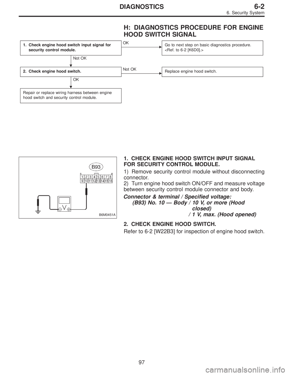
B6M0451A
1. CHECK ENGINE HOOD SWITCH INPUT SIGNAL
FOR SECURITY CONTROL MODULE.
1) Remove security control module without disconnecting
connector.
2) Turn engine hood switch ON/OFF and measure voltage
between security control module connector and body.
Connector & terminal / Specified voltage:
(B93) No. 10—Body / 10 V, or more (Hood
closed)
/ 1 V, max. (Hood opened)
2. CHECK ENGINE HOOD SWITCH.
Refer to 6-2 [W22B3] for inspection of engine hood switch.
�
�
97
6-2DIAGNOSTICS
6. Security System
Page 1843 of 3342
 OR REAR GATE
SWITCH (WAGON) SIGNAL
1. Check trunk lid switch (SEDAN) or rear gate
switch (WAGON) input signal for security
control module.
Not OK")
I: DIAGNOSTICS PROCEDURE FOR TRUNK
LID SWITCH (SEDAN) OR REAR GATE
SWITCH (WAGON) SIGNAL
1. Check trunk lid switch (SEDAN) or rear gate
switch (WAGON) input signal for security
control module.
Not OK
�OK
Go to next step on basic diagnostics procedure.
2. Check trunk lid switch (SEDAN) or rear gate
switch (WAGON).
OK
�Not OK
Replace trunk lid switch (or rear gate switch).
Repair or replace wiring harness between trunk lid
switch (or rear gate switch) and security control
module.
B6M0450A
1. CHECK TRUNK LID SWITCH (SEDAN) OR REAR
GATE SWITCH (WAGON) INPUT SIGNAL FOR
SECURITY CONTROL MODULE.
1) Remove security control module without disconnecting
connector.
2) Turn trunk lid switch (or rear gate switch) ON/OFF and
measure voltage between security control module connec-
tor and body.
Connector & terminal / Specified voltage:
(B93) No. 11—Body / 10 V, or more
(Lid or gate closed)
/ 1 V, max.
(Lid or gate opened)
2. CHECK TRUNK LID SWITCH (SEDAN) OR REAR
GATE SWITCH (WAGON).
Refer to 6-2 [W8B2/W8B3] for inspection of trunk lid switch/
rear gate switch.
NOTE:
The trunk lid switch/rear gate switch is used for both trunk
room light/luggage room light.
�
�
98
6-2DIAGNOSTICS
6. Security System
Page 1845 of 3342

K: DIAGNOSTICS PROCEDURE FOR KEY
CYLINDER LOCK/UNLOCK SWITCH AND
TAMPER SWITCH SIGNAL
NOTE:
Key cylinder lock switch, key cylinder unlock switch and
tamper switch are combined as a unit.
1. Check key cylinder switch input signal for
security control module.
Not OK
�OK
Go to next step on basic diagnostics procedure.
2. Check key cylinder switch.
OK
�Not OK
Replace key cylinder switch.
Repair or replace wiring harness between key
cylinder switch and security control module.
B6M0499A
1. CHECK KEY CYLINDER SWITCH INPUT SIGNAL
FOR SECURITY CONTROL MODULE.
1) Remove security control module without disconnecting
connector.
2) Measure voltage between security control module con-
nector and body while turning each key cylinder with igni-
tion key.
Doors (RH and LH), and rear gate (WAGON)
Connector & terminal / Specified voltage:
(B93) No. 2—Body/1V,max. (LOCK position)
/ 10 V, or more (other than
LOCK position)
B6M0447A
(B93) No. 14—Body/1V,max. (UNLOCK position)
/ 10 V, or more (other than
UNLOCK position)
�
�
100
6-2DIAGNOSTICS
6. Security System
Page 1903 of 3342

40. FA MODE FOR ENGINE
Function
modeLED No. Contents Display LED“ON”requirements
FA 03 Neutral switch NT When neutral position signal is entered.
7 Test mode connector UD When test mode connector is connected.
8 AT/MT identification signal AT When AT identification signal is entered.
9 Ignition switch IG When ignition switch is turned ON.
FA 11 Radiator fan relay 2 R2 When radiator fan relay 2 is in function.
2 Knock signal KS When knock signal is entered.
3 Purge control solenoid valve CN When purge control solenoid valve is in function.
4 Fuel pump relay FP When fuel pump relay is in function.
6 Radiator fan relay 1 R1 When radiator fan relay 1 is in function.
7 Air conditioner relay AR When air conditioner relay is in function.
8 Air conditioner switch AC When air conditioner switch is turned ON.
FA 22 AEC signal EC When AEC signal is entered.
3 EAM signal AM When EAM signal is gone out.
4 AEB signal EB When AEB signal is entered.
6 AET signal ET When AET signal is entered.
7 Engine torque control signal TR When engine torque control signal is entered.
FA3 7 Pressure sources switching solenoid valve BRWhen pressure sources switching solenoid valve
is in function.
FA 41 Catalyst CA When diagnosis of catalyzer is finished.
2 EGR system E1 When diagnosis of EGR system is finished.
3 California spec. vehicle identification signal FCWhen Federal spec. vehicle identification signal is
entered.
8 Rear oxygen sensor signal OR When rear oxygen sensor mixture ratio is rich.
9 Front oxygen sensor signal O2 When front oxygen sensor mixture ratio is rich.
FA 56 Vent control solenoid valve AL When vent control solenoid valve is in function.
7 EGR solenoid valve ER When EGR solenoid valve is in function.
8 Pressure control solenoid valve PCWhen pressure control solenoid valve is in
function.
52
2-7ON-BOARD DIAGNOSTICS II SYSTEM
3. Diagnosis System
Page 1904 of 3342

LED No. Signal name Display
1——
2——
3 Neutral switch NT
4——
5——
6——
7 Test mode connector UD
8 Identification of AT model AT
9 Ignition switch IG
0——
——NT——
—UD AT IG—
1
2345
67890
41. FUNCTION MODE: FA0
—ON↔OFF SIGNAL—
Requirement for LED“ON”.
LED No. 3�On MT model, gear position is in neutral.
�On AT model, shift position is in“P”or“N”.
LED No. 7 Test mode connector is connected.
LED No. 8 Vehicle is AT model.
LED No. 9 Ignition switch is turned ON.
LED No. Signal name Display
1 Radiator fan relay 2 R2
2 Knock signal KS
3Purge control solenoid
valveCN
4 Fuel pump relay FP
5——
6 Radiator fan relay 1 R1
7 A/C relay AR
8 A/C switch AC
9——
0——
R2 KS CN FP—
R1 AR AC——
1
2345
67890
42. FUNCTION MODE: FA1
—ON↔OFF SIGNAL—
Requirement for LED“ON”.
LED No. 1 Radiator fan relay 2 is turned ON.
LED No. 2 Engine is knocking.
LED No. 3 Purge control solenoid valve is in function.
LED No. 4 Fuel pump relay is turned ON.
LED No. 6 Radiator fan relay 1 is turned ON.
LED No. 7 A/C relay is turned ON.
LED No. 8 A/C switch is turned ON.
NOTE:
�When LED No. 1, 3, 4, 6 and 7 blinks with the test mode
connector connected and the ignition switch turned to ON,
the corresponding part is functioning properly.
�When LED No. 4 illuminates for only 2 seconds after the
ignition switch is turned to ON, (and then goes out), the
corresponding part is functioning properly.
�LED No. 3 is applicable only to the models not equipped
with enhanced evaporative emission control system.
53
2-7ON-BOARD DIAGNOSTICS II SYSTEM
3. Diagnosis System
Page 1905 of 3342

LED No. Signal name Display
1——
2 AEC signal EC
3 EAM signal AM
4 AEB signal EB
5——
6 AET signal ET
7Engine torque control
signalTR
8——
9——
0——
—EC AM EB—
ET TR———
1
2345
67890
43. FUNCTION MODE: FA2
—ON↔OFF SIGNAL—
Requirement for LED“ON”.
LED No. 2 ECM entered the AEC signal emitted from
TCS C/M.
LED No. 3 EAM signal goes out.
LED No. 4 ECM entered the AEB signal emitted from
TCS C/M.
LED No. 6 ECM entered the AET signal emitted from
TCS C/M.
LED No. 7 ECM entered the torque control signal emit-
ted from TCM.
LED No. Signal name Display
1——
2——
3——
4——
5——
6——
7Pressure sources switching
solenoid valveBR
8——
9——
0——
—————
—BR———
1
2345
67890
44. FUNCTION MODE: FA3
—ON↔OFF SIGNAL—
Requirement for LED“ON”.
LED No. 7 Pressure sources switching solenoid valve is
in function.
NOTE:
When LED No. 7 blinks with the test mode connector con-
nected and the ignition switch turned to ON, the corre-
sponding part is functioning properly.
54
2-7ON-BOARD DIAGNOSTICS II SYSTEM
3. Diagnosis System
Page 1906 of 3342

LED No. Signal name Display
1 Catalyst CA
2 EGR system E1
3California model
identification signalFC
4——
5——
6——
7——
8 Rear oxygen sensor signal OR
9 Front oxygen sensor signal O2
0——
CA E1 FC——
——OR O2—
1
2345
67890
45. FUNCTION MODE: FA4
—ON↔OFF SIGNAL—
Requirement for LED“ON”.
LED No. 1 Diagnosis of catalyzer is finished.
LED No. 2 Diagnosis of EGR system is finished.
LED No. 3 Vehicle is Federal specifications.
LED No. 8 Rear oxygen sensor mixture ratio is rich.
LED No. 9 Front oxygen sensor mixture ratio is rich.
LED No. Signal name Display
1——
2——
3——
4——
5——
6 Vent control solenoid valve AL
7 EGR solenoid valve ER
8Pressure control solenoid
valvePC
9——
0——
—————
AL ER PC——
1
2345
67890
46. FUNCTION MODE: FA5
—ON↔OFF SIGNAL—
Requirement for LED“ON”.
LED No. 6 Vent control solenoid valve is in function.
LED No. 7 EGR solenoid valve is in function.
LED No. 8 Pressure control solenoid valve is in func-
tion.
NOTE:
When LED No. 6, 7 and 8 blinks with the test mode con-
nector connected and the ignition switch turned to ON, the
corresponding part is functioning properly.
55
2-7ON-BOARD DIAGNOSTICS II SYSTEM
3. Diagnosis System