Page 2989 of 3342

: Are the tone wheel installation bolts tight-
ened securely?
: Go to step10L10.
: Tighten tone wheel")
10L9CHECK INSTALLATION OF TONE
WHEEL.
Tightening torque:
13±3 N⋅m (1.3±0.3 kg-m, 9±2.2 ft-lb)
: Are the tone wheel installation bolts tight-
ened securely?
: Go to step10L10.
: Tighten tone wheel installation bolts securely.
G4M0700
10L10
CHECK ABS SENSOR GAP.
Measure tone wheel to pole piece gap over entire perim-
eter of the wheel.
: Is the gap within the specifications shown
in the following table?
SpecificationsFront wheel Rear wheel
0.9—1.4 mm
(0.035—0.055 in)0.7—1.2 mm
(0.028—0.047 in)
G4M0701
: Go to step10L11.
: Adjust the gap.
NOTE:
Adjust the gap using spacer (Part No. 26755AA000). If
spacers cannot correct the gap, replace worn sensor or
worn tone wheel.
10L11
CHECK OSCILLOSCOPE.
: Is an oscilloscope available?
: Go to step10L12.
: Go to step10L13.
10L12
CHECK ABS SENSOR SIGNAL.
1) Raise all four wheels of ground.
2) Turn ignition switch OFF.
3) Connect the oscilloscope to the connector (F1) or con-
nector (B100) in accordance with trouble code.
4) Turn ignition switch ON.
11 3
4-4dBRAKES [ABS 5.3i TYPE]
10. Diagnostics Chart with Select Monitor
Page 2995 of 3342
B4M0952
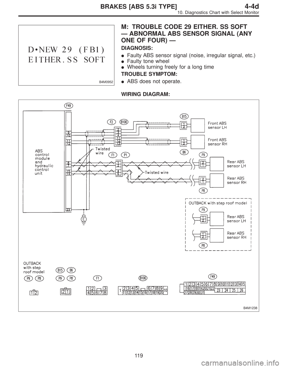
M: TROUBLE CODE 29 EITHER. SS SOFT
—ABNORMAL ABS SENSOR SIGNAL (ANY
ONE OF FOUR)—
DIAGNOSIS:
�Faulty ABS sensor signal (noise, irregular signal, etc.)
�Faulty tone wheel
�Wheels turning freely for a long time
TROUBLE SYMPTOM:
�ABS does not operate.
WIRING DIAGRAM:
B4M1238
11 9
4-4dBRAKES [ABS 5.3i TYPE]
10. Diagnostics Chart with Select Monitor
Page 2997 of 3342

: Are the tone wheel installation bolts tight-
ened securely?
: Go to step10M7.
: Tighten tone wheel")
10M6CHECK INSTALLATION OF TONE
WHEEL.
Tightening torque:
13±3 N⋅m (1.3±0.3 kg-m, 9±2.2 ft-lb)
: Are the tone wheel installation bolts tight-
ened securely?
: Go to step10M7.
: Tighten tone wheel installation bolts securely.
G4M0700
10M7
CHECK ABS SENSOR GAP.
Measure tone wheel to pole piece gap over entire perim-
eter of the wheel.
: Is the gap within the specifications shown
in the following table?
SpecificationsFront wheel Rear wheel
0.9—1.4 mm
(0.035—0.055 in)0.7—1.2 mm
(0.028—0.047 in)
G4M0701
: Go to step10M8.
: Adjust the gap.
NOTE:
Adjust the gap using spacer (Part No. 26755AA000). If
spacers cannot correct the gap, replace worn sensor or
worn tone wheel.
10M8
CHECK OSCILLOSCOPE.
: Is an oscilloscope available?
: Go to step10M9.
: Go to step10M10.
10M9
CHECK ABS SENSOR SIGNAL.
1) Raise all four wheels of ground.
2) Turn ignition switch OFF.
3) Connect the oscilloscope to the connector (F1) or con-
nector (B100) in accordance with trouble code.
4) Turn ignition switch ON.
121
4-4dBRAKES [ABS 5.3i TYPE]
10. Diagnostics Chart with Select Monitor
Page 3009 of 3342
 Turn ignition switch to OFF.
2) Disconnect connector from ABSCM&H/U.
3) Measure resistance between ABSCM&H/U and chassis
ground.
Connector & terminal")
B4M1243A
10V1CHECK GROUND CIRCUIT OF
ABSCM&H/U.
1) Turn ignition switch to OFF.
2) Disconnect connector from ABSCM&H/U.
3) Measure resistance between ABSCM&H/U and chassis
ground.
Connector & terminal
(F49) No. 23—Chassis ground:
: Is the resistance less than 0.5Ω?
: Go to step10V2.
: Repair ABSCM&H/U ground harness.
10V2CHECK POOR CONTACT IN CONNEC-
TORS.
: Is there poor contact in connectors between
battery, ignition switch and ABSCM&H/U?
: Repair connector.
: Go to step10V3.
10V3
CHECK SOURCES OF SIGNAL NOISE.
: Is the car telephone or the wireless trans-
mitter properly installed?
: Go to step10V4.
: Properly install the car telephone or the wireless
transmitter.
10V4
CHECK SOURCES OF SIGNAL NOISE.
: Are noise sources (such as an antenna)
installed near the sensor harness?
: Install the noise sources apart from the sensor
harness.
: Go to step10V5.
10V5
CHECK ABSCM&H/U.
1) Turn ignition switch to OFF.
2) Connect all connectors.
3) Erase the memory.
4) Perform inspection mode.
5) Read out the trouble code.
: Is the same trouble code as in the current
diagnosis still being output?
: Replace ABSCM&H/U.
: Go to step10V6.
133
4-4dBRAKES [ABS 5.3i TYPE]
10. Diagnostics Chart with Select Monitor
Page 3153 of 3342

Main power supply 2�Battery voltage is present when main power is tu")
5. Control Module I/O Signal
G6M0015
ContentTerminal
No.Measuring conditions and I/O signals (ignition switch ON and engine idling)
Main power supply 2�Battery voltage is present when main power is turned ON.
�“0”volt is present when main power is turned OFF.
Inhibitor switch (AT) (U.S.A.)
N position switch (AT) (CANADA)4�“0”volt is present when selector lever is set to P or N position (CANADA: N position only).
�Battery voltage is present when selector lever is other than P or N position (CANADA: N
position only).
Air valve 5�“0”volt is present when vehicle is stopped.
�ON-and-OFF (“0”-and-battery voltage) operation is alternately repeated while cruise control
is operating.
GND 6—
Vacuum pump motor 7�“0”volt is present when vehicle is stopped.
�ON-and-OFF (“0”-and-battery voltage) operation is alternately repeated while cruise control
is operating.
Data link connector 8—
RESUME/ACCEL switch 9�Battery voltage is present when switch is turned ON.
�“0”volt is present when switch is turned OFF.
SET/COAST switch 10�Battery voltage is present when switch is turned ON.
�“0”volt is present when switch is turned OFF.
Ignition switch 12�Battery voltage is present when ignition switch is turned ON.
�“0”volt is present when ignition switch is turned OFF.
Release valve 13�“0”volt is present when vehicle is stopped.
�ON-and-OFF (“0”-and-battery voltage) operation is alternately repeated while cruise control
is operating.
Power supply to vacuum pump
motor, air valve, release valve14�“0”volt is present when vehicle is stopped.
�Battery voltage is present while cruise control is operating.
Cruise main switch 15�Battery voltage is present during pressing the main switch, and then approx. 12 V is
present while switch is turned ON.
�“0”volt is present when switch is turned OFF.
Brake switch 16Turn the cruise main switch to ON and leave clutch pedal released (MT).
Then check that;
�“0”volt is present when brake pedal is depressed.
�Battery voltage is present when brake pedal is released.
Additionally only in MT vehicle, keep the cruise main switch to ON and leave brake pedal
released.
Then check that;
�“0”volt is present when clutch pedal is depressed.
�Battery voltage is present when clutch pedal is released.
Data link connector 17—
Data link connector 18—
Vehicle speed sensor 2 19Lift-up the vehicle until all four wheels are raised off ground, and then rotate any wheel manu-
ally.
Approx. 5 and 0 volt pulse signals are alternately input to cruise control module.
Stop light switch 20Turn ignition switch to OFF.
Then check that;
�Battery voltage is present when brake pedal is depressed.
�“0”volt is present when brake pedal is released.
NOTE:
Voltage at terminals 5, 7, 13 and 14 cannot be checked unless vehicle is driving by cruise control operation.
7
6-2BODY ELECTRICAL SYSTEM
5. Control Module I/O Signal
Page 3155 of 3342

B: ON-BOARD DIAGNOSIS WITH SELECT
MONITOR
1. GENERAL
The on-board diagnosis function of the cruise control sys-
tem uses an external select monitor.
The on-board diagnosis function operates in two
categories, which are used depending on the type of prob-
lems;
�Cruise cancel conditions diagnosis
�Real-time diagnosis
Applicable cartridge No.: 498349601
�Cruise cancel conditions diagnosis
This category of diagnosis requires actual vehicle driv-
ing in order to determine the cause, (as when cruise
speed is cancelled during driving although cruise cancel
condition is not entered).
Cruise control module memory stores the cancel condi-
tion (Code No.) which occurred during driving. When
there are plural cancel conditions (Code No.), they are
shown in order, for 2 seconds per Code No., on the
select monitor.
CAUTION:
�The cruise control memory stores not only the
cruise“cancel”which occurred (although“cancel”
operation is not entered by the driver), but also the
“cancel”condition input by the driver.
�The content of memory is cleared when ignition
switch or cruise main switch is turned OFF.
�Real-time diagnosis
The real-time diagnosis function is used to determine
whether or not the input of output signal system is in good
order, according to signal emitted from switches, sensors,
etc.
Vehicle cannot be driven at cruise speed because prob-
lems occurs in the cruise control system or its associ-
ated circuits.
Monitor the signal conditions from switches and sen-
sors.
9
6-2BODY ELECTRICAL SYSTEM
6. Diagnostics Chart for On-board Diagnosis System
Page 3164 of 3342
BR
5 Inhibitor switch (AT) N
6——
7——
8——
9——
10—�")
LED No. Signal name Display
1 SET/COAST switch SE
2 RESUME/ACCEL switch RE
3 Stop light switch ST
4�Brake switch
�Clutch switch (MT)BR
5 Inhibitor switch (AT) N
6——
7——
8——
9——
10——
SE RE ST BR N
—————
1
2345
678910
1. CHECK THE SIGNAL USING A SELECT MONITOR.
1) Turn ignition switch to ON.
2) Turn cruise control main switch to ON.
3) Set select monitor in“FA 0”mode.
4) Check signals for proper operation.
(1) When pushing the SET switch:
LED No. 1 goes out—lights.
(2) When pushing the RESUME switch:
LED No. 2 goes out—lights.
B6M0533
B6M0527
2. CHECK THE CRUISE CONTROL COMMAND
SWITCH.
1) Disconnect connector from command switch.
2) Measure voltage between connector (S1) and body.
Connector & terminal / Specified voltage:
(S1) No. 1—Body / 10 V, or more
3) Check for harness short circuit between command
switch and body.
Terminals / Specified resistance:
No. 2—Body / 1 MΩ, min.
No. 3—Body / 1 MΩ, min.
B6M0534
4) Measure resistance between each terminal of switch
side connector to check the switch operation.
Terminals:
No. 1—No. 2 (SET/COAST SWITCH)
No. 1—No. 3 (RESUME/ACCEL SWITCH)
Specified resistance:
10Ω, max. (ON)
1MΩ, min. (OFF)
18
6-2BODY ELECTRICAL SYSTEM
8. Diagnostics Chart with Trouble Code
Page 3166 of 3342
BR
5 Inhibitor switch (AT) N
6——
7——
8——
9——
10—�")
LED No. Signal name Display
1 SET/COAST switch SE
2 RESUME/ACCEL switch RE
3 Stop light switch ST
4�Brake switch
�Clutch switch (MT)BR
5 Inhibitor switch (AT) N
6——
7——
8——
9——
10——
SE RE ST BR N
—————
1
2345
678910
1. CHECK THE SIGNAL USING A SELECT MONITOR.
1) Turn ignition switch to ON.
2) Turn cruise control main switch to ON.
3) Apply parking brake securely.
4) Set select monitor in“FA 0”mode.
5) Release the clutch pedal. (MT model)
6) Depress the brake pedal and check signals for proper
operation.
Stop light switch: LED No. 3 goes out—lights.
Brake switch : LED No. 4 goes out—lights.
7) Release the brake pedal.
8) Depress the clutch pedal and check signal for proper
operation. (MT model)
Clutch switch: LED No. 4 goes out—lights.
9) Set the selector lever from D to N position and check
signal for proper operation. (AT model)
Inhibitor switch: LED No. 5 goes out—lights.
G6M0183
2. CHECK BRAKE SWITCH AND STOP LIGHT
SWITCH.
1) Remove connector of stop and brake switch.
2) Check circuit between each terminal.
Pedal operationBrake switch between
No. 1—No. 4Stop light switch between
No. 2—No. 3
Depressing the
brake pedal.1MΩ,ormore 1Ω, or less
Without
depressing the
brake pedal.1Ω, or less 1 MΩ,ormore
G6M0184
3. CHECK CLUTCH SWITCH. (MT MODEL)
1) Disconnect connector from clutch switch.
2) Check continuity of the clutch switch.
Terminals / Specified resistance:
No. 1—No. 2 / 10Ω, max. (Without pedal
depressing.)
/1MΩ, min. (Pedal depressing.)
20
6-2BODY ELECTRICAL SYSTEM
8. Diagnostics Chart with Trouble Code