Page 2518 of 3342

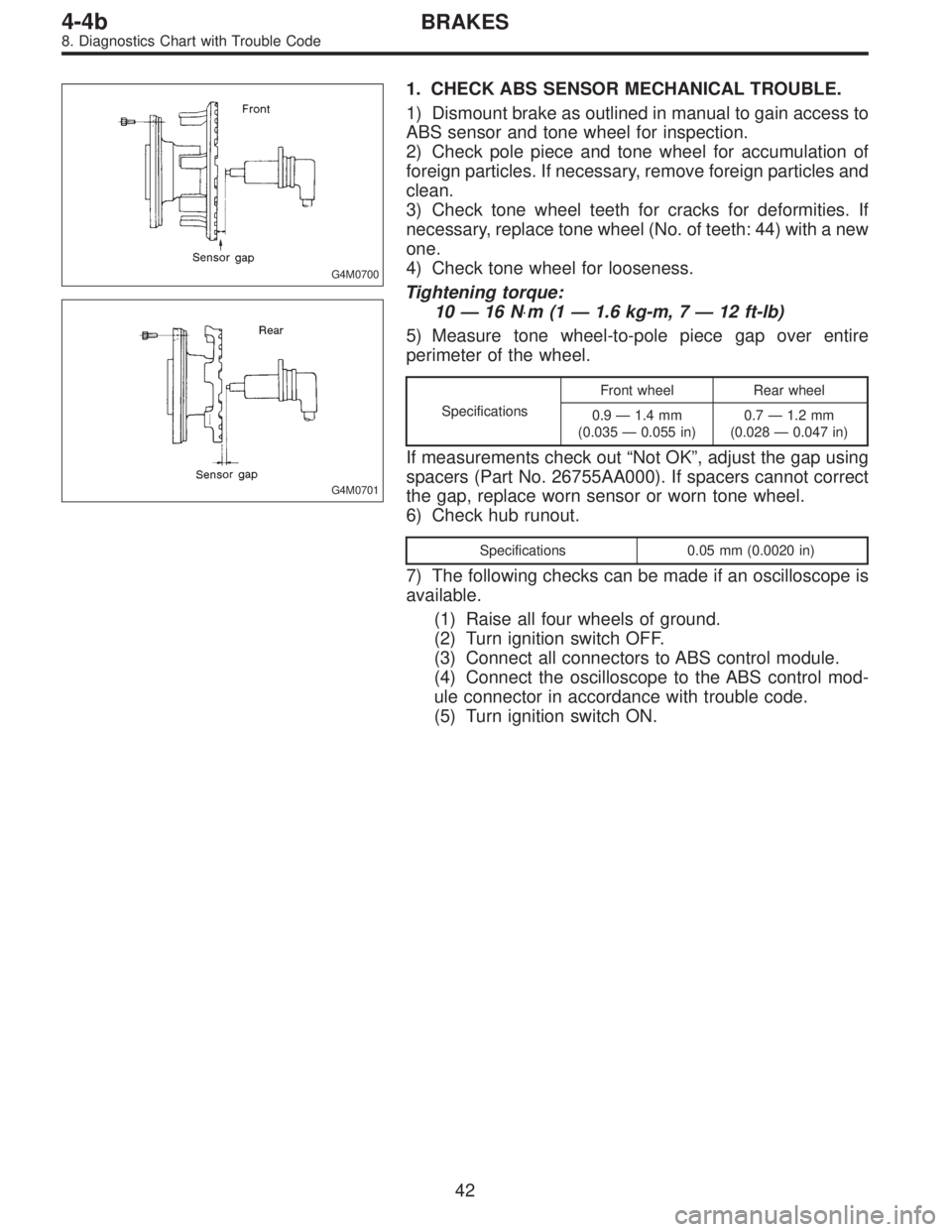
G4M0700
G4M0701
1. CHECK ABS SENSOR MECHANICAL TROUBLE.
1) Dismount brake as outlined in manual to gain access to
ABS sensor and tone wheel for inspection.
2) Check pole piece and tone wheel for accumulation of
foreign particles. If necessary, remove foreign particles and
clean.
3) Check tone wheel teeth for cracks for deformities. If
necessary, replace tone wheel (No. of teeth: 44) with a new
one.
4) Check tone wheel for looseness.
Tightening torque:
10—16 N⋅m(1—1.6 kg-m, 7—12 ft-lb)
5) Measure tone wheel-to-pole piece gap over entire
perimeter of the wheel.
SpecificationsFront wheel Rear wheel
0.9—1.4 mm
(0.035—0.055 in)0.7—1.2 mm
(0.028—0.047 in)
If measurements check out“Not OK”, adjust the gap using
spacers (Part No. 26755AA000). If spacers cannot correct
the gap, replace worn sensor or worn tone wheel.
6) Check hub runout.
Specifications 0.05 mm (0.0020 in)
7) The following checks can be made if an oscilloscope is
available.
(1) Raise all four wheels of ground.
(2) Turn ignition switch OFF.
(3) Connect all connectors to ABS control module.
(4) Connect the oscilloscope to the ABS control mod-
ule connector in accordance with trouble code.
(5) Turn ignition switch ON.
42
4-4bBRAKES
8. Diagnostics Chart with Trouble Code
Page 2520 of 3342
B4M0407A
3. CHECK RESISTANCE OF ABS SENSOR.
1) Turn ignition switch OFF.
2) Disconnect connector from ABS sensor.
3) Measure resistance between ABS sensor connector ter-
minals.
TROUBLE CODE / Connector & terminal:
22 / (B6) No. 1—No. 2
24 / (B15) No. 1—No. 2
26 / (P8) No. 1—No. 2
28 / (P9) No. 1—No. 2
Specified resistance: 0.8—1.2 kΩ
4. CHECK HARNESS CONNECTOR BETWEEN ABS/
TCS CONTROL MODULE AND ABS SENSOR.
Check for poor contacts in plug-in connectors. Refer to
“Basic checks”in“FOREWORD”.
44
4-4bBRAKES
8. Diagnostics Chart with Trouble Code
Page 2521 of 3342
5. CHECK SOURCES OF SIGNAL NOISE.
1) Check that the mobile phone, personal radio and other
wireless apparatus are correctly installed.
2) Check that the antenna and other possible noise
sources are distant enough from the sensor harness.
3) Check that the sealed wires of the front harness sensor
(in the engine room) are securely grounded.
4) Check that between ABS/TCS control module and the
rear sensor harness has the correct twist pitch.
Twist pitch:
25 mm (0.98 in) or less
6. CHECK HYDRAULIC UNIT OPERATIONS.
1) Operate the ABS sequence control and check that the
brake fluid pressure at the malfunctioning brake line
increases and decreases properly.
45
4-4bBRAKES
8. Diagnostics Chart with Trouble Code
Page 2542 of 3342

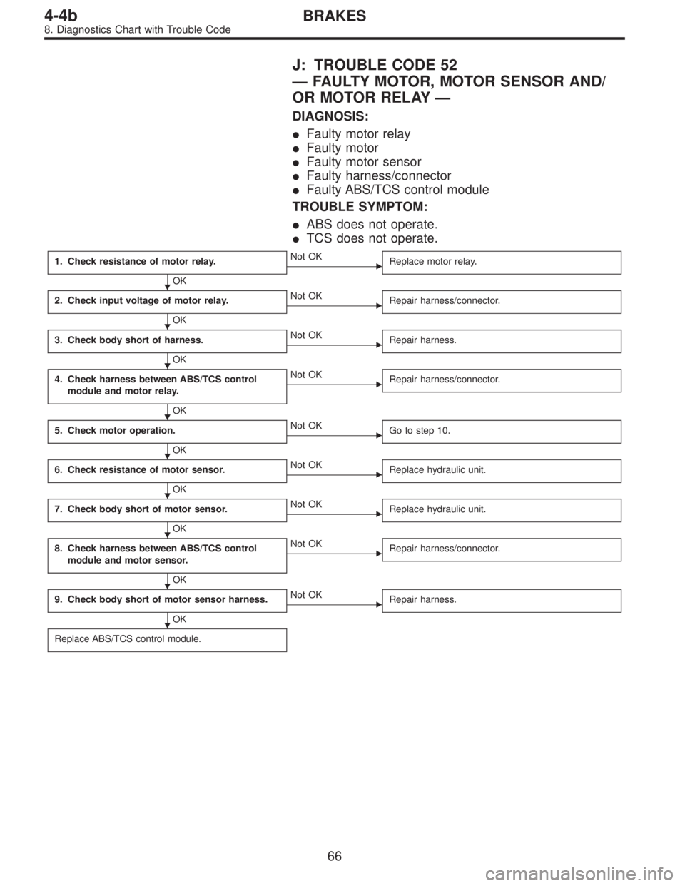
J: TROUBLE CODE 52
—FAULTY MOTOR, MOTOR SENSOR AND/
OR MOTOR RELAY—
DIAGNOSIS:
�Faulty motor relay
�Faulty motor
�Faulty motor sensor
�Faulty harness/connector
�Faulty ABS/TCS control module
TROUBLE SYMPTOM:
�ABS does not operate.
�TCS does not operate.
1. Check resistance of motor relay.
OK
�Not OK
Replace motor relay.
2. Check input voltage of motor relay.
OK
�Not OK
Repair harness/connector.
3. Check body short of harness.
OK
�Not OK
Repair harness.
4. Check harness between ABS/TCS control
module and motor relay.
OK
�Not OK
Repair harness/connector.
5. Check motor operation.
OK
�Not OK
Go to step 10.
6. Check resistance of motor sensor.
OK
�Not OK
Replace hydraulic unit.
7. Check body short of motor sensor.
OK
�Not OK
Replace hydraulic unit.
8. Check harness between ABS/TCS control
module and motor sensor.
OK
�Not OK
Repair harness/connector.
9. Check body short of motor sensor harness.
OK
�Not OK
Repair harness.
Replace ABS/TCS control module.
�
�
�
�
�
�
�
�
�
66
4-4bBRAKES
8. Diagnostics Chart with Trouble Code
Page 2545 of 3342

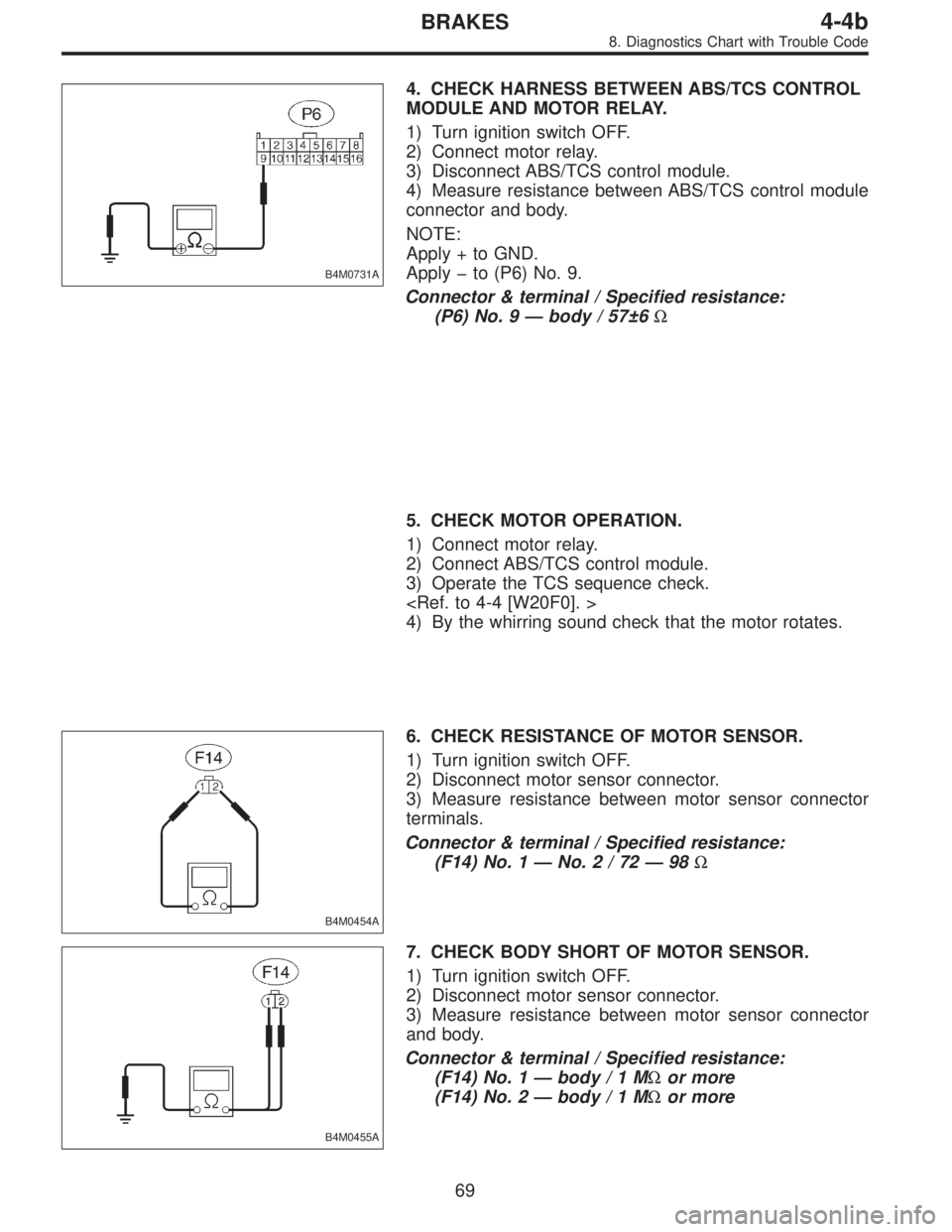
B4M0731A
4. CHECK HARNESS BETWEEN ABS/TCS CONTROL
MODULE AND MOTOR RELAY.
1) Turn ignition switch OFF.
2) Connect motor relay.
3) Disconnect ABS/TCS control module.
4) Measure resistance between ABS/TCS control module
connector and body.
NOTE:
Apply + to GND.
Apply�to (P6) No. 9.
Connector & terminal / Specified resistance:
(P6) No. 9—body / 57±6Ω
5. CHECK MOTOR OPERATION.
1) Connect motor relay.
2) Connect ABS/TCS control module.
3) Operate the TCS sequence check.
4) By the whirring sound check that the motor rotates.
B4M0454A
6. CHECK RESISTANCE OF MOTOR SENSOR.
1) Turn ignition switch OFF.
2) Disconnect motor sensor connector.
3) Measure resistance between motor sensor connector
terminals.
Connector & terminal / Specified resistance:
(F14) No. 1—No.2/72—98Ω
B4M0455A
7. CHECK BODY SHORT OF MOTOR SENSOR.
1) Turn ignition switch OFF.
2) Disconnect motor sensor connector.
3) Measure resistance between motor sensor connector
and body.
Connector & terminal / Specified resistance:
(F14) No. 1—body/1MΩor more
(F14) No. 2—body/1MΩor more
69
4-4bBRAKES
8. Diagnostics Chart with Trouble Code
Page 2546 of 3342

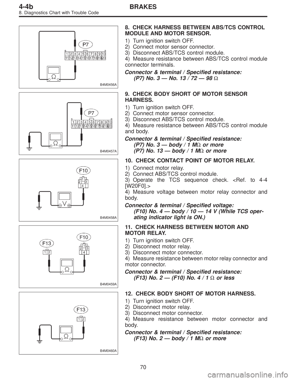
B4M0456A
8. CHECK HARNESS BETWEEN ABS/TCS CONTROL
MODULE AND MOTOR SENSOR.
1) Turn ignition switch OFF.
2) Connect motor sensor connector.
3) Disconnect ABS/TCS control module.
4) Measure resistance between ABS/TCS control module
connector terminals.
Connector & terminal / Specified resistance:
(P7) No. 3—No. 13 / 72—98Ω
B4M0457A
9. CHECK BODY SHORT OF MOTOR SENSOR
HARNESS.
1) Turn ignition switch OFF.
2) Connect motor sensor connector.
3) Disconnect ABS/TCS control module.
4) Measure resistance between ABS/TCS control module
and body.
Connector & terminal / Specified resistance:
(P7) No. 3—body/1MΩor more
(P7) No. 13—body/1MΩor more
B4M0458A
10. CHECK CONTACT POINT OF MOTOR RELAY.
1) Connect motor relay.
2) Connect ABS/TCS control module.
3) Operate the TCS sequence check.
[W20F0].>
4) Measure voltage between motor relay connector and
body.
Connector & terminal / Specified voltage:
(F10) No. 4—body / 10—14 V (While TCS oper-
ating indicator light is ON.)
B4M0459A
11. CHECK HARNESS BETWEEN MOTOR AND
MOTOR RELAY.
1) Turn ignition switch OFF.
2) Disconnect motor relay.
3) Disconnect motor connector.
4) Measure resistance between motor relay connector and
motor connector.
Connector & terminal / Specified resistance:
(F13) No. 2—(F10) No.4/1Ωor less
B4M0460A
12. CHECK BODY SHORT OF MOTOR HARNESS.
1) Turn ignition switch OFF.
2) Disconnect motor relay.
3) Disconnect motor connector.
4) Measure resistance between motor connector and
body.
Connector & terminal / Specified resistance:
(F13) No. 2—body/1MΩor more
70
4-4bBRAKES
8. Diagnostics Chart with Trouble Code
Page 2547 of 3342
B4M0461A
13. CHECK GROUND CIRCUIT OF MOTOR.
1) Turn ignition switch OFF.
2) Disconnect motor connector.
3) Measure resistance between motor connector and
body.
Connector & terminal / Specified resistance:
(F13) No. 1—body / 1Ωor less
NOTE:
The check can also be made by analyzing the waves of the
motor sensor output signal with oscilloscope during the
TCS sequence control operation. If the ECM female con-
nector end gives correct value, skip steps 6 through 9
above.
If not, operate the TCS sequence control again and mea-
sure the value at motor sensor male connector end with the
motor sensor connector removed. If the value is OK, pro-
ceed with steps 8 and 9 above.
71
4-4bBRAKES
8. Diagnostics Chart with Trouble Code
Page 2548 of 3342
K: TROUBLE CODE 54
—FAULTY STROKE SENSOR AND/OR STOP
LIGHT SWITCH—
DIAGNOSIS:
�Faulty stroke sensor
�Faulty stop light switch
�Faulty pump unit in hydraulic unit
�Faulty ABS/TCS control module
�Faulty harness/connector
TROUBLE SYMPTOM:
�ABS and TCS do not operate.
�No kick-back ocuurs while ABS is functioning.
�Only when the stop light switch circuit is broken, the ABS
functions while TCS does not. (TCS warning light only illu-
minates.)
72
4-4bBRAKES
8. Diagnostics Chart with Trouble Code