Page 2582 of 3342

�Faulty harness/connector
�Faulty ABS")
B4M0508
K: TROUBLE CODE 28
1. RL.SS W.SPEED
—Irregular signals from rear left ABS sensor—
DIAGNOSIS:
�Faulty ABS sensor signal (noise, irregular signal, etc.)
�Faulty harness/connector
�Faulty ABS/TCS control module
TROUBLE SYMPTOM:
�ABS and TCS do not operate.
NOTE:
The procedures used are the same as those for FR.SS
W.SPEED.
B4M0509
2. RL.SS OR MV
—Irregular signals from rear left ABS sensor in
decompressing mode—
DIAGNOSIS:
�Faulty ABS sensor signal (noise, irregular signal, etc.)
�Faulty hydraulic unit
�Faulty harness/connector
�Faulty ABS/TCS control module
TROUBLE SYMPTOM:
�ABS and TCS do not operate.
NOTE:
The procedures used are the same as those for FR.SS OR
MV.
B4M0510
3. RL.SS OVER
—Excessive speed of rear left ABS sensor signal—
DIAGNOSIS:
�Faulty ABS sensor signal (noise, irregular signal, etc.)
�Faulty harness/connector
�Faulty ABS/TCS control module
TROUBLE SYMPTOM:
�ABS and TCS do not operate.
NOTE:
The procedures used are the same as those for FR.SS
OVER.
106
4-4bBRAKES
10. Diagnostic Chart with Select Monitor
Page 2592 of 3342
B4M0524
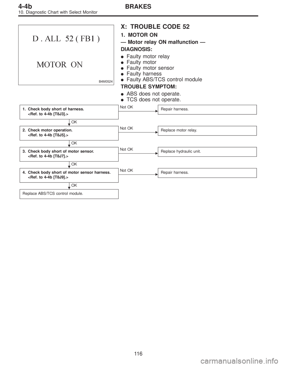
X: TROUBLE CODE 52
1. MOTOR ON
—Motor relay ON malfunction—
DIAGNOSIS:
�Faulty motor relay
�Faulty motor
�Faulty motor sensor
�Faulty harness
�Faulty ABS/TCS control module
TROUBLE SYMPTOM:
�ABS does not operate.
�TCS does not operate.
1. Check body short of harness.
OK
�Not OK
Repair harness.
2. Check motor operation.
OK
�Not OK
Replace motor relay.
3. Check body short of motor sensor.
OK
�Not OK
Replace hydraulic unit.
4. Check body short of motor sensor harness.
OK
�Not OK
Repair harness.
Replace ABS/TCS control module.
�
�
�
�
11 6
4-4bBRAKES
10. Diagnostic Chart with Select Monitor
Page 2593 of 3342
B4M0525
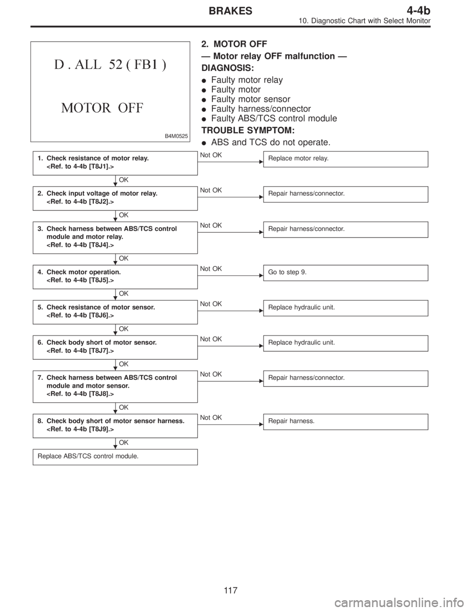
2. MOTOR OFF
—Motor relay OFF malfunction—
DIAGNOSIS:
�Faulty motor relay
�Faulty motor
�Faulty motor sensor
�Faulty harness/connector
�Faulty ABS/TCS control module
TROUBLE SYMPTOM:
�ABS and TCS do not operate.
1. Check resistance of motor relay.
OK
�Not OK
Replace motor relay.
2. Check input voltage of motor relay.
OK
�Not OK
Repair harness/connector.
3. Check harness between ABS/TCS control
module and motor relay.
OK
�Not OK
Repair harness/connector.
4. Check motor operation.
OK
�Not OK
Go to step 9.
5. Check resistance of motor sensor.
OK
�Not OK
Replace hydraulic unit.
6. Check body short of motor sensor.
OK
�Not OK
Replace hydraulic unit.
7. Check harness between ABS/TCS control
module and motor sensor.
OK
�Not OK
Repair harness/connector.
8. Check body short of motor sensor harness.
OK
�Not OK
Repair harness.
Replace ABS/TCS control module.
�
�
�
�
�
�
�
�
11 7
4-4bBRAKES
10. Diagnostic Chart with Select Monitor
Page 2594 of 3342
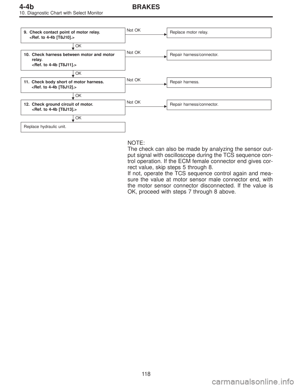
9. Check contact point of motor relay.
OK
�Not OK
Replace motor relay.
10. Check harness between motor and motor
relay.
OK
�Not OK
Repair harness/connector.
11. Check body short of motor harness.
OK
�Not OK
Repair harness.
12. Check ground circuit of motor.
OK
�Not OK
Repair harness/connector.
Replace hydraulic unit.
NOTE:
The check can also be made by analyzing the sensor out-
put signal with oscilloscope during the TCS sequence con-
trol operation. If the ECM female connector end gives cor-
rect value, skip steps 5 through 8.
If not, operate the TCS sequence control again and mea-
sure the value at motor sensor male connector end, with
the motor sensor connector disconnected. If the value is
OK, proceed with steps 7 through 8 above.
�
�
�
�
11 8
4-4bBRAKES
10. Diagnostic Chart with Select Monitor
Page 2595 of 3342

B4M0526
Y: TROUBLE CODE 54
1. B.SW HARD
—Break and short circuit at stroke sensor or its
wiring—
DIAGNOSIS:
�Faulty stroke sensor
�Faulty harness/connector
�Faulty stop light switch
�Faulty ABS/TCS control module
TROUBLE SYMPTOM:
�ABS and TCS do not operate.
NOTE:
Operate the function F09 in select monitor TCS mode, and
read the sensor output step.
If system is normal, the output reading is 1 when brake
pedal is not depressed, and it changes from 2 to 3, 4 and
5 in accordance with the brake pedal depressing. If so, skip
check steps 1 through 5.
1. Check resistance of stroke sensor.
OK
�Not OK
Replace stroke sensor.
2. Check stroke sensor operation.
OK
�Not OK
Replace stroke sensor.
3. Check body short of stroke sensor.
OK
�Not OK
Replace stroke sensor.
4. Check harness between stroke sensor and
ABS/TCS control module.
OK
�Not OK
Repair harness/connector.
5. Check body short of stroke sensor harness.
OK
�Not OK
Repair harness.
Replace ABS/TCS control module.
�
�
�
�
�
11 9
4-4bBRAKES
10. Diagnostic Chart with Select Monitor
Page 2596 of 3342
B4M0527
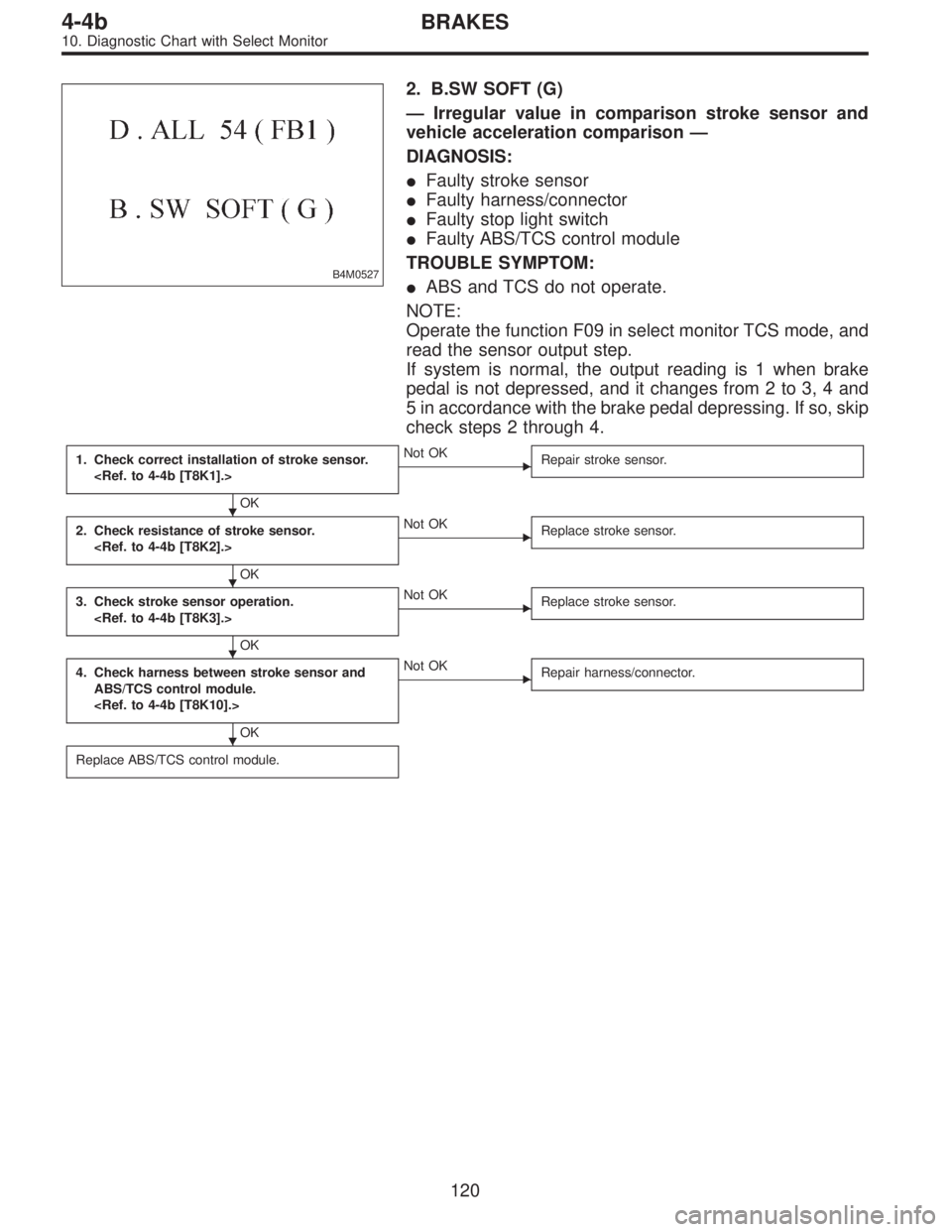
2. B.SW SOFT (G)
—Irregular value in comparison stroke sensor and
vehicle acceleration comparison—
DIAGNOSIS:
�Faulty stroke sensor
�Faulty harness/connector
�Faulty stop light switch
�Faulty ABS/TCS control module
TROUBLE SYMPTOM:
�ABS and TCS do not operate.
NOTE:
Operate the function F09 in select monitor TCS mode, and
read the sensor output step.
If system is normal, the output reading is 1 when brake
pedal is not depressed, and it changes from 2 to 3, 4 and
5 in accordance with the brake pedal depressing. If so, skip
check steps 2 through 4.
1. Check correct installation of stroke sensor.
OK
�Not OK
Repair stroke sensor.
2. Check resistance of stroke sensor.
OK
�Not OK
Replace stroke sensor.
3. Check stroke sensor operation.
OK
�Not OK
Replace stroke sensor.
4. Check harness between stroke sensor and
ABS/TCS control module.
OK
�Not OK
Repair harness/connector.
Replace ABS/TCS control module.
�
�
�
�
120
4-4bBRAKES
10. Diagnostic Chart with Select Monitor
Page 2597 of 3342

—Irregular value in stroke sensor and brake light
switch comparison—
DIAGNOSIS:
�Faulty stroke sensor
�Faulty stop light switch
�Faulty harness/connector
�Faulty ABS/TCS c")
B4M0528
3. B.SW SOFT (B)
—Irregular value in stroke sensor and brake light
switch comparison—
DIAGNOSIS:
�Faulty stroke sensor
�Faulty stop light switch
�Faulty harness/connector
�Faulty ABS/TCS control module
TROUBLE SYMPTOM:
�ABS and TCS do not operate.
NOTE:
Operate the function F09 in select monitor TCS mode, and
read the sensor output step.
If system is normal, the output reading is 1 when brake
pedal is not depressed, and it changes from 2 to 3, 4 and
5 in accordance with the brake pedal depressing. If so, skip
check steps 1 and 2 through 7.
Then, operate the function FA0 and check the stop and
brake switches by B1 LED ON/OFF. If system is normal,
LED comes on when depressing brake pedal, and goes off
when not depressing. If so, skip check steps 3 through 6.
1. Check resistance of stroke sensor.
OK
�Not OK
Replace stroke sensor.
2. Check stroke sensor operation.
OK
�Not OK
Replace stroke sensor.
3. Check contact point of stop light switch.
OK
�Not OK
Replace stroke sensor.
4. Check body short of stop light switch.
OK
�Not OK
Replace stroke sensor.
5. Check power supply of stop light switch.
OK
�Not OK
Repair harness/connector.
6. Check input voltage of ABS/TCS control mod-
ule.
OK
�Not OK
Repair harness/connector.
7. Check harness between stroke sensor and
ABS/TCS control module.
OK
�Not OK
Repair harness/connector.
Replace ABS/TCS control module.
�
�
�
�
�
�
�
121
4-4bBRAKES
10. Diagnostic Chart with Select Monitor
Page 2598 of 3342

—Comparison between stroke sensor and pump
output—
DIAGNOSIS:
�Faulty stroke sensor
�Faulty harness/connector
�Faulty pump unit in hydraulic unit
�Faulty stop light switch")
B4M0529
4. B.SW SOFT (P)
—Comparison between stroke sensor and pump
output—
DIAGNOSIS:
�Faulty stroke sensor
�Faulty harness/connector
�Faulty pump unit in hydraulic unit
�Faulty stop light switch
�Faulty ABS/TCS control module
NOTE:
Operate the function F09 in select monitor TCS mode, and
read the sensor output step.
If system is normal, the output reading is 1 when brake
pedal is not depressed, and it changes from 2 to 3, 4 and
5 in accordance with the brake pedal depressing. If so, skip
check steps 2 through 4.
1. Check correct installation of stroke sensor.
OK
�Not OK
Repair stroke sensor.
2. Check resistance of stroke sensor.
OK
�Not OK
Replace stroke sensor.
3. Check stroke sensor operation.
OK
�Not OK
Replace stroke sensor.
4. Check harness between stroke sensor and
ABS/TCS control module.
OK
�Not OK
Repair harness/connector.
5. Check pump unit operation.
OK
�Not OK
Replace hydraulic unit.
Replace ABS/TCS control module.
�
�
�
�
�
122
4-4bBRAKES
10. Diagnostic Chart with Select Monitor