Page 2599 of 3342
B4M0530
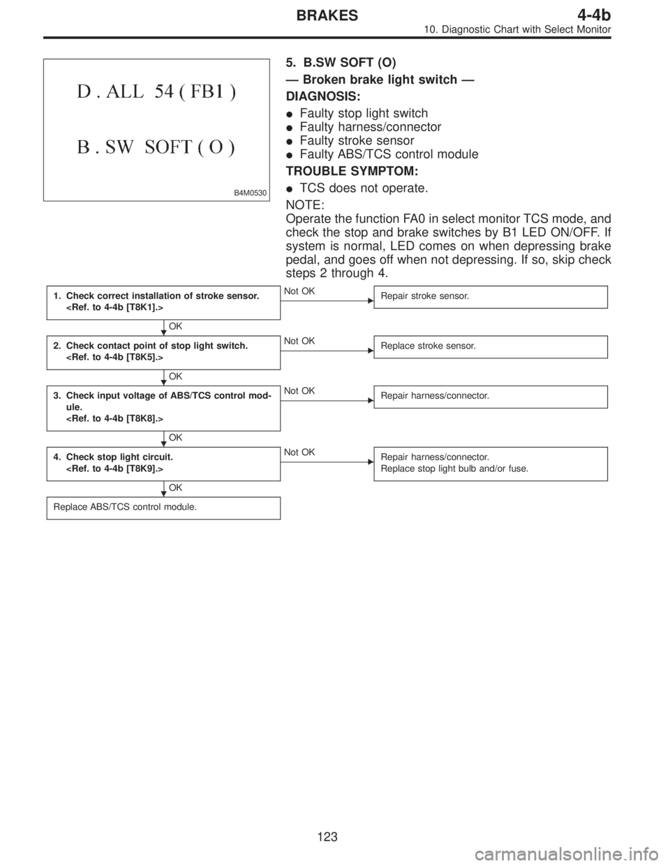
5. B.SW SOFT (O)
—Broken brake light switch—
DIAGNOSIS:
�Faulty stop light switch
�Faulty harness/connector
�Faulty stroke sensor
�Faulty ABS/TCS control module
TROUBLE SYMPTOM:
�TCS does not operate.
NOTE:
Operate the function FA0 in select monitor TCS mode, and
check the stop and brake switches by B1 LED ON/OFF. If
system is normal, LED comes on when depressing brake
pedal, and goes off when not depressing. If so, skip check
steps 2 through 4.
1. Check correct installation of stroke sensor.
OK
�Not OK
Repair stroke sensor.
2. Check contact point of stop light switch.
OK
�Not OK
Replace stroke sensor.
3. Check input voltage of ABS/TCS control mod-
ule.
OK
�Not OK
Repair harness/connector.
4. Check stop light circuit.
OK
�Not OK
Repair harness/connector.
Replace stop light bulb and/or fuse.
Replace ABS/TCS control module.
�
�
�
�
123
4-4bBRAKES
10. Diagnostic Chart with Select Monitor
Page 2600 of 3342
B4M0531
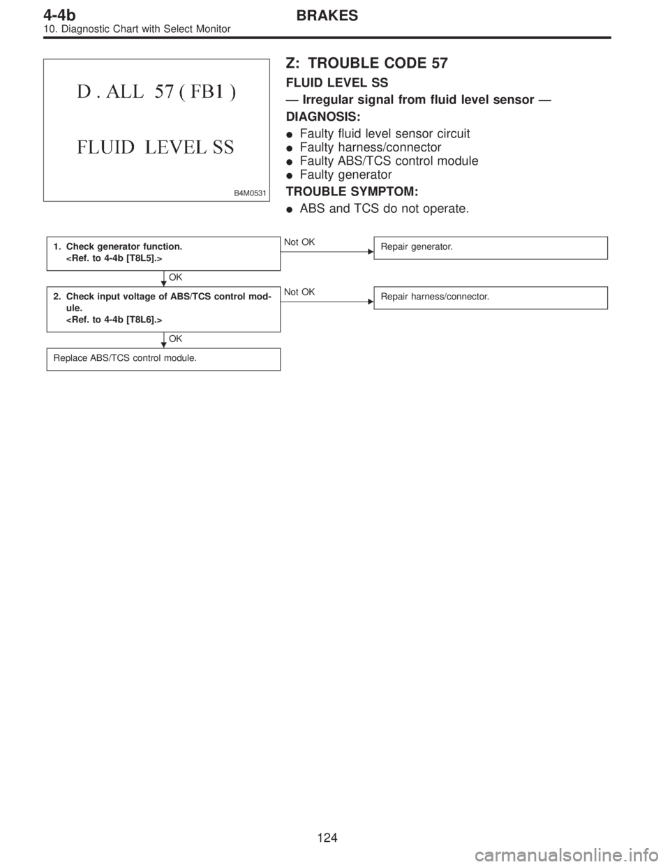
Z: TROUBLE CODE 57
FLUID LEVEL SS
—Irregular signal from fluid level sensor—
DIAGNOSIS:
�Faulty fluid level sensor circuit
�Faulty harness/connector
�Faulty ABS/TCS control module
�Faulty generator
TROUBLE SYMPTOM:
�ABS and TCS do not operate.
1. Check generator function.
OK
�Not OK
Repair generator.
2. Check input voltage of ABS/TCS control mod-
ule.
OK
�Not OK
Repair harness/connector.
Replace ABS/TCS control module.
�
�
124
4-4bBRAKES
10. Diagnostic Chart with Select Monitor
Page 2601 of 3342

B4M0532
AA: TROUBLE CODE 58
PRESSURE SW
—Faulty pressure switch—
DIAGNOSIS:
�Faulty pressure
�Faulty stop light switch
�Faulty ABS/TCS control module
�Faulty harness/connector
TROUBLE SYMPTOM:
�TCS does not operate.
NOTE:
Check using the select monitor.
Operate the function FA0 in select monitor TCS mode. The
stop and brake switches can be checked by B1 LED
ON/OFF. If system is normal, LED comes on when
depressing brake pedal, and goes off when not depressing.
If so, skip check steps 5 through 8.
1. Check contact point of pressure switch.
OK
�Not OK
Replace hydraulic unit.
2. Check body short of pressure switch.
OK
�Not OK
Replace hydraulic unit.
3. Check harness between pressure switch and
ABS/TCS control module.
OK
�Not OK
Repair harness/connector.
4. Check body short of pressure switch harness.
OK
�Not OK
Repair harness.
5. Check contact point of stop light switch.
OK
�Not OK
Replace stroke sensor.
6. Check body short of stop light switch.
OK
�Not OK
Replace stroke sensor.
7. Check power supply of stop light switch.
OK
�Not OK
Repair harness.
8. Check input voltage of ABS/TCS control mod-
ule.
OK
�Not OK
Repair harness/connector.
Replace ABS/TCS control module.
�
�
�
�
�
�
�
�
125
4-4bBRAKES
10. Diagnostic Chart with Select Monitor
Page 2603 of 3342

11. General Diagnostics Table
��: Primary expected causes�: Secondary expected causes
Trouble conditions
SymptomsHydraulic
unit
Speed sensor
P valve
Master cylinder
Calipers and piston
Pad
Rotor
Hand brake
Piping
Mixture of air
Brake booster and check valve
Axle and wheel
Alignment
Play of pedal
Rough road surface
Semicylindrical road surface
Loose or worn suspension
Tire
Wrong connection and wiring
Stroke sensor Solenoid valve
Motor
Mount bush ABS function
Directional stability cannot be
obtained when braking.Vehicle turns to right or left.����������� ������������
Vehicle spins.�������������
Out-of-order brakesLong braking distance
��� ���������������
Brakes lock.������� � ��
Brakes drag.�����������������
Long pedal stroke� ���� �����
Abnormal vehicle pitching�� ������
Unstable braking force. One-
side brake refuses to work.����������� ����������
TCS function
When accelerating abruptly,
directional stability cannot be
obtained when traveling on a
slippery road surface.Vehicle moves unsteadily.������������������
Handle refuses to work.�������������
Handle loses control.���������� ���������
Bad acceleration, engine stall-
ing (In addition to the causes
listed here, check the ECM
specifications.)Engine stalls. Engine speed
fails to increase.�����������
Engine speed increases sud-
denly.��������������������
Vibration occurs and abnormal
noise is produced.
�When applying brakes abruptly.
�When accelerating abruptly.
�When driving on a slippery
road surface.Brake pedal heavily vibrates
when applying brakes.
�� � � �������
Loud hydraulic unit operating
noise��������
Noise is produced from front
of vehicle.���������������������
Noise is produced from rear of
vehicle.����������������
NOTE:
This list includes no engine failure and transmission failure.
127
4-4bBRAKES
11. General Diagnostics Table
Page 2605 of 3342

6. INSPECTOR
Before advancing the vehicle after the engine starts, drive
the pump motor and valve for a very short time to function-
ally check the ABS/TCS brakes. It is not abnormal if, at this
time, operating noises of the valve and motor are produced
or kickback of the brake pedal is felt when stepping on the
pedal.
7. WHEN ATTACHING CHAINS
It is sometimes a good idea to turn off the TCS for better
advancing and accelerating the vehicle.
8. WHEN A DRUM TESTER IS USED (SPEEDOMETER
TEST, EXHAUST GAS TEST, BRAKE TEST, ETC.)
Before performing tests, turn the TCS off by operating the
TCS OFF switch or disconnect the fuse of ECM input
power source to put the machine out of operation. If oper-
ating other parts to put the TCS in the fail state
intentionally, trouble code will be recorded. Make sure to
clear the memory. Also, in a 2-wheel tester, wheel speed
sensor failure can be detected, making the TCS fail. This
case is also not abnormal and clearing the memory is
required.
129
4-4bBRAKES
12. Phenomena Peculiar to the System
Page 2606 of 3342

1. Supplemental Restraint System
“Airbag”
Airbag system wiring harness is routed near the ABS con-
trol module, ABS sensor and hydraulic control unit.
CAUTION:
�All Airbag system wiring harness and connectors
are colored yellow. Do not use electrical test equip-
ment on these circuit.
�Be careful not to damage Airbag system wiring har-
ness when servicing the ABS control module, ABS
sensor and hydraulic control unit.
2. Pre-inspection
Before performing diagnostics, check the following items
which might affect ABS problems:
A: MECHANICAL INSPECTION
1. POWER SUPPLY
1) Measure battery voltage and specific gravity of electro-
lyte.
Standard voltage: 12 V, or more
Specific gravity: Above 1.260
2) Check the condition of the main and other fuses, and
harnesses and connectors. Also check for proper ground-
ing.
2. BRAKE FLUID
1) Check brake fluid level.
2) Check brake fluid leakage.
3. BRAKE DRAG
Check brake drag.
4. BRAKE PAD AND ROTOR
Check brake pad and rotor.
5. TIRE SPECIFICATIONS, TIRE WEAR AND AIR
PRESSURE
Check tire specifications, tire wear and air pressure.
to 4-2 [S1A0].>
2
4-4cBRAKES [ABS 5.3 TYPE]
1. Supplemental Restraint System“Airbag”- 2. Pre-inspection
Page 2607 of 3342

1. Supplemental Restraint System
“Airbag”
Airbag system wiring harness is routed near the ABS con-
trol module, ABS sensor and hydraulic control unit.
CAUTION:
�All Airbag system wiring harness and connectors
are colored yellow. Do not use electrical test equip-
ment on these circuit.
�Be careful not to damage Airbag system wiring har-
ness when servicing the ABS control module, ABS
sensor and hydraulic control unit.
2. Pre-inspection
Before performing diagnostics, check the following items
which might affect ABS problems:
A: MECHANICAL INSPECTION
1. POWER SUPPLY
1) Measure battery voltage and specific gravity of electro-
lyte.
Standard voltage: 12 V, or more
Specific gravity: Above 1.260
2) Check the condition of the main and other fuses, and
harnesses and connectors. Also check for proper ground-
ing.
2. BRAKE FLUID
1) Check brake fluid level.
2) Check brake fluid leakage.
3. BRAKE DRAG
Check brake drag.
4. BRAKE PAD AND ROTOR
Check brake pad and rotor.
5. TIRE SPECIFICATIONS, TIRE WEAR AND AIR
PRESSURE
Check tire specifications, tire wear and air pressure.
to 4-2 [S1A0].>
2
4-4cBRAKES [ABS 5.3 TYPE]
1. Supplemental Restraint System“Airbag”- 2. Pre-inspection
Page 2609 of 3342
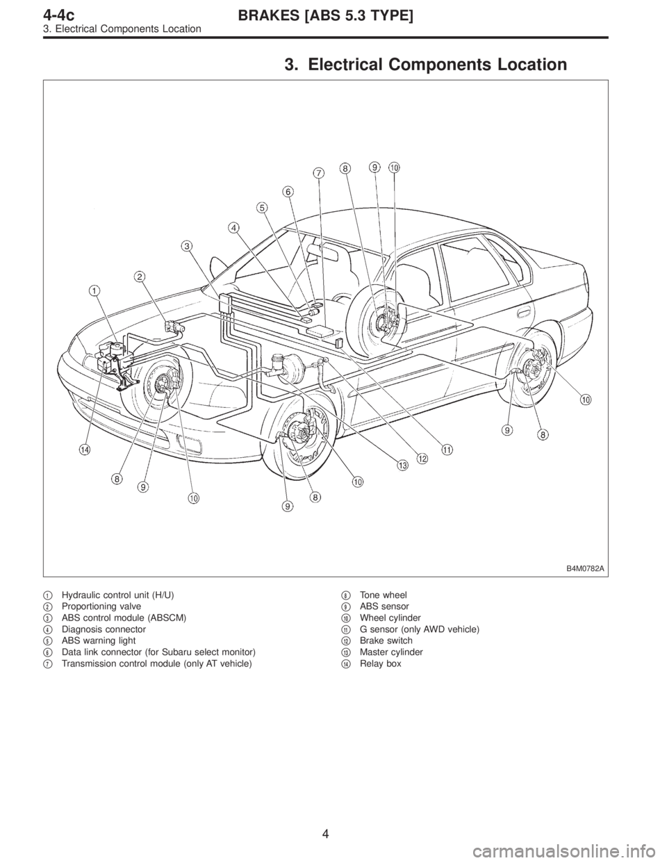
3. Electrical Components Location
B4M0782A
�1Hydraulic control unit (H/U)
�
2Proportioning valve
�
3ABS control module (ABSCM)
�
4Diagnosis connector
�
5ABS warning light
�
6Data link connector (for Subaru select monitor)
�
7Transmission control module (only AT vehicle)�
8Tone wheel
�
9ABS sensor
�
10Wheel cylinder
�
11G sensor (only AWD vehicle)
�
12Brake switch
�
13Master cylinder
�
14Relay box
4
4-4cBRAKES [ABS 5.3 TYPE]
3. Electrical Components Location