Page 1416 of 3342
B4M1222
E: INSTALLATION
1) Install ABSCM&H/U.
CAUTION:
Confirm that the specifications of the ABSCM&H/U
conforms to the vehicle specifications.
Tightening torque:
18±5 N⋅m (1.8±0.5 kg-m, 13.0±3.6 ft-lb)
2) Connect brake pipes to their correct ABSCM&H/U con-
nections.
3) Using cable clip, secure ABSCM&H/U harness to
bracket.
4) Connect connector to ABSCM&H/U.
CAUTION:
�Be sure to remove all foreign matter from inside the
connector before connecting.
�Ensure that the ABSCM&H/U connector is securely
locked.
5) Install air intake duct.
6) Connect ground cable to battery.
7) Bleed air from the brake system.
23. ABS Sensor (ABS 5.3i Type)
24. G Sensor (ABS 5.3i Type)
130
4-4SERVICE PROCEDURE
22. ABS Control Module and Hydraulic Control Unit (ABSCM&H/U) (ABS 5.3i Type) - 24. G Sensor (ABS 5.3i Type)
Page 1417 of 3342
B4M1222
E: INSTALLATION
1) Install ABSCM&H/U.
CAUTION:
Confirm that the specifications of the ABSCM&H/U
conforms to the vehicle specifications.
Tightening torque:
18±5 N⋅m (1.8±0.5 kg-m, 13.0±3.6 ft-lb)
2) Connect brake pipes to their correct ABSCM&H/U con-
nections.
3) Using cable clip, secure ABSCM&H/U harness to
bracket.
4) Connect connector to ABSCM&H/U.
CAUTION:
�Be sure to remove all foreign matter from inside the
connector before connecting.
�Ensure that the ABSCM&H/U connector is securely
locked.
5) Install air intake duct.
6) Connect ground cable to battery.
7) Bleed air from the brake system.
23. ABS Sensor (ABS 5.3i Type)
24. G Sensor (ABS 5.3i Type)
130
4-4SERVICE PROCEDURE
22. ABS Control Module and Hydraulic Control Unit (ABSCM&H/U) (ABS 5.3i Type) - 24. G Sensor (ABS 5.3i Type)
Page 1422 of 3342
1. Pedal (MT Model)
1. 2200 cc MODEL
B4M0737A
�1Accelerator pedal
�
2Bushing
�
3Holder
�
4Accelerator bracket
�
5Stopper
�
6Clip
�
7Accelerator spring
�
8Accelerator pedal spring
�
9Spring pin
�
10Accelerator pedal pad
�
11Accelerator stopper
�
12Clip
�
13Accelerator plate�
14Pedal bracket
�
15Stop light switch (Without T.C.S.) /
stroke sensor (With T.C.S.)
�
16Brake pedal
�
17Spacer
�
18Snap pin
�
19Brake pedal pad
�
20Clevis pin
�
21Brake pedal spring
�
22Washer
�
23Clutch pedal pad
�
24Clutch pedal
�
25Bushing assist�
26Spring assist
�
27Clutch cable clamp
�
28Clutch cable
�
29Mass damper
�
30Clutch switch (Starter interlock)
�
31Clutch switch (With cruise control)
Tightening torque: N⋅m (kg-m, ft-lb)
T1: 5.9±1.5 (0.60±0.15, 4.3±1.1)
T2: 8±2 (0.8±0.2, 5.8±1.4)
T3: 18±5 (1.8±0.5, 13.0±3.6)
T4: 29±7 (3.0±0.7, 21.7±5.1)
3
4-5COMPONENT PARTS
1. Pedal (MT Model)
Page 1424 of 3342
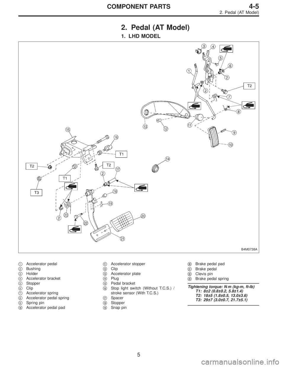
2. Pedal (AT Model)
1. LHD MODEL
B4M0738A
�1Accelerator pedal
�
2Bushing
�
3Holder
�
4Accelerator bracket
�
5Stopper
�
6Clip
�
7Accelerator spring
�
8Accelerator pedal spring
�
9Spring pin
�
10Accelerator pedal pad�
11Accelerator stopper
�
12Clip
�
13Accelerator plate
�
14Plug
�
15Pedal bracket
�
16Stop light switch (Without T.C.S.) /
stroke sensor (With T.C.S.)
�
17Spacer
�
18Stopper
�
19Snap pin�
20Brake pedal pad
�
21Brake pedal
�
22Clevis pin
�
23Brake pedal spring
Tightening torque: N⋅m (kg-m, ft-lb)
T1: 8±2 (0.8±0.2, 5.8±1.4)
T2: 18±5 (1.8±0.5, 13.0±3.6)
T3: 29±7 (3.0±0.7, 21.7±5.1)
5
4-5COMPONENT PARTS
2. Pedal (AT Model)
Page 1879 of 3342
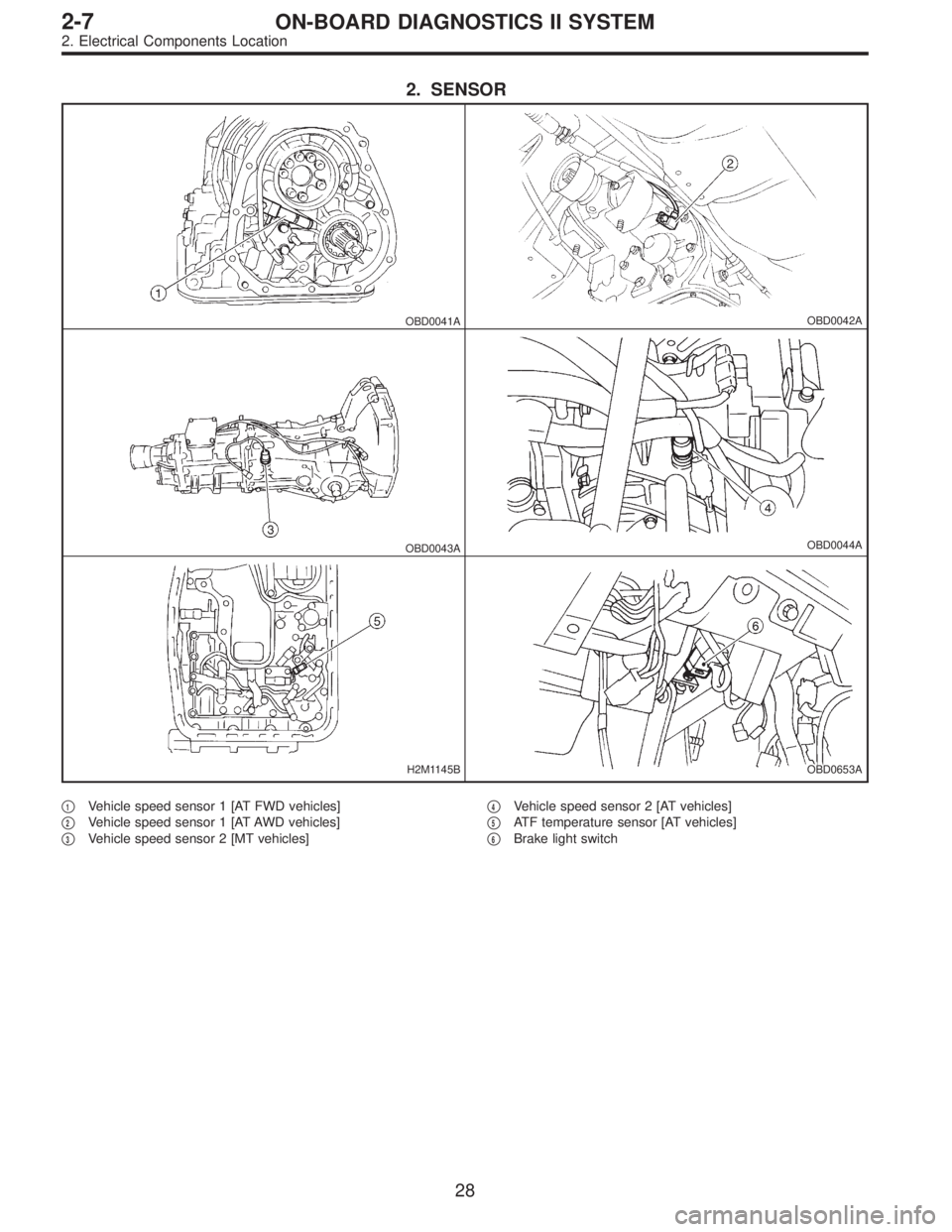
2. SENSOR
OBD0041AOBD0042A
OBD0043AOBD0044A
H2M1145BOBD0653A
�1Vehicle speed sensor 1 [AT FWD vehicles]
�
2Vehicle speed sensor 1 [AT AWD vehicles]
�
3Vehicle speed sensor 2 [MT vehicles]�
4Vehicle speed sensor 2 [AT vehicles]
�
5ATF temperature sensor [AT vehicles]
�
6Brake light switch
28
2-7ON-BOARD DIAGNOSTICS II SYSTEM
2. Electrical Components Location
Page 1976 of 3342

B: GENERAL DIAGNOSTICS TABLE WITH
NONCONFORMITY SYMPTOM FOR
AUTOMATIC TRANSMISSION
Problem parts
Inhibitor switch
Control module
Vehicle speed sensor 1
Vehicle speed sensor 2
Select cable
Select lever
FWD switch
Starter motor and harness
Throttle position sensor
Hold switch
Accumulator (“N”—“D”)
Accumulator (2A)
Accumulator (4A)
Accumulator (3R)
ATF temperature sensor
Strainer
Duty solenoid A
Duty solenoid B
Shift solenoid 1
Shift solenoid 2
Shift solenoid 3
Control valve
Detent spring
Manual plate
Transfer clutch
Transfer valve
Transfer pipe
Duty solenoid C
Forward clutch
Symptom1234567891011121314151617181920212223242526272829
Starter does not rotate when select lever is
in“P”or“N.”; starter rotates when select
lever is“R”,“D”,“3”or“2.”����
Abnormal noise when select lever is in“P”or
“N.”��
Hissing noise occurs during standing starts.�
Noise occurs while driving in“D
1”range.
Noise occurs while driving in“D
2”range.
Noise occurs while driving in“D
3”range.
Noise occurs while driving in“D
4”range.
Engine stalls while shifting from one range to
another.�
Vehicle moves when select lever is in“N.”�
Shock occurs when select lever is moved
from“N”to“D.”�� �
Excessive time lag occurs when select lever
is moved from“N”to“D.”��
Shock occurs when select lever is moved
from“N”to“R.”���
Excessive time lag occurs when select lever
is moved from“N”to“R.”�
Vehicle does not start in any shift range
(engine revving up).��
Vehicle does not start in any shift range
(engine stall).
Vehicle does not start in“R”range only
(engine revving up).�� �
Vehicle does not start in“R”range only
(engine stall).�
Vehicle does not start in“D”or“3”range
(engine revving up).�
Vehicle does not start in“D”,“3”or“2”range
(engine revving up).�
Vehicle does not start in“D”,“3”or“2”range
(engine stall).
Vehicle starts in“R”range only (engine rev-
ving up).�
Acceleration during standing starts is poor
(high stall rpm).��
Acceleration during standing starts is poor
(low stall rpm).
Acceleration is poor when select lever is in
“D”,“3”or“2”range (normal stall rpm).��
Acceleration is poor when select lever is in
“R”(normal stall rpm).�
No shift occurs from 1st to 2nd gear.��� � �� �
No shift occurs from 2nd to 3rd gear.��
No shift occurs from 3rd to 4th gear.�����
No“kick-down”shifts occur.��
Engine brake is not effected when select
lever is in“3”range.�� � �
1234567891011121314151617181920212223242526272829
125
2-7ON-BOARD DIAGNOSTICS II SYSTEM
9. General Diagnostic Table
Page 1978 of 3342

Problem parts
Inhibitor switch
Control module
Vehicle speed sensor 1
Vehicle speed sensor 2
Select cable
Select lever
FWD switch
Starter motor and harness
Throttle position sensor
Hold switch
Accumulator (“N”—“D”)
Accumulator (2A)
Accumulator (4A)
Accumulator (3R)
ATF temperature sensor
Strainer
Duty solenoid A
Duty solenoid B
Shift solenoid 1
Shift solenoid 2
Shift solenoid 3
Control valve
Detent spring
Manual plate
Transfer clutch
Transfer valve
Transfer pipe
Duty solenoid C
Forward clutch
Symptom1234567891011121314151617181920212223242526272829
Engine brake is not effected when select
lever is in“3”or“2”range.
Engine brake is not effected when select
lever is in“1”range.�
Shift characteristics are erroneous.���� � �
No lock-up occurs.����
Vehicle cannot be set in“D”range power
mode.��
“D”range power mode cannot be released.���
Parking brake is not effected.��
Shift lever cannot be moved or is hard to
move from“P”range.��
Select lever is hard to move.�� ��
Select lever is too light to move (unreason-
able resistance).��
ATF spurts out.
Differential oil spurts out.
Differential oil level changes excessively.
Odor is produced from oil supply pipe.��
Shock occurs when select lever is moved
from“1”to“2”range.� ���� �
Slippage occurs when select lever is moved
from“1”to“2”range.� ���� �
Shock occurs when select lever is moved
from“2”to“3”range.������
Slippage occurs when select lever is moved
from“2”to“3”range.������
Shock occurs when select lever is moved
from“3”to“4”range.� � ��� �
Slippage occurs when select lever is moved
from“3”to“4”range.� � ��� �
Shock occurs when select lever is moved
from“3”to“2”range.�����
Shock occurs when select lever is moved
from“D”to“1”range.�����
Shock occurs when select lever is moved
from“2”to“1”range.�����
Shock occurs when accelerator pedal is
released at medium speeds.�����
Vibration occurs during straight-forward
operation.��
Select lever slips out of position during
acceleration or while driving on rough terrain.�� ��
Vibration occurs during turns (tight corner
“braking”phenomenon).��� �� � �� �
Front wheel slippage occurs during standing
starts.� � � �� � � ����
Vehicle is not set in FWD mode.�� ���
1234567891011121314151617181920212223242526272829
127
2-7ON-BOARD DIAGNOSTICS II SYSTEM
9. General Diagnostic Table
Page 1981 of 3342
Item Page
P0341 CAM
—R Camshaft position sensor circuit range/performance problem 230
P0400 EGR Exhaust gas recirculation flow malfunction 232
P0403 EGRSOL")
DTC
No.Abbreviation
(Subaru Select Monitor)Item Page
P0341 CAM
—R Camshaft position sensor circuit range/performance problem 230
P0400 EGR Exhaust gas recirculation flow malfunction 232
P0403 EGRSOL Exhaust gas recirculation circuit low input 237
P0420 CAT Catalyst system efficiency below threshold 240
P0440 EVAP Evaporative emission control system malfunction 242
P0441 CPC
—F Evaporative emission control system incorrect purge flow 246
P0443 CPC Evaporative emission control system purge control valve circuit low input 248
P0446 VCMSOL
—LO Evaporative emission control system vent control low input 251
P0451 TNKP
—F Evaporative emission control system pressure sensor range/performance problem 254
P0452 TNKP
—LOW Evaporative emission control system pressure sensor low input 256
P0453 TNKP
—HI Evaporative emission control system pressure sensor high input 261
P0461 FLVL
—R Fuel level sensor circuit range/performance problem 267
P0462 FLVL
—LOW Fuel level sensor circuit low input 269
P0463 FLVL
—HI Fuel level sensor circuit high input 275
P0500 VSP Vehicle speed sensor malfunction 281
P0505 ISC Idle control system malfunction 283
P0506 ISC
—RLOW Idle control system RPM lower than expected 289
P0507 ISC
—RHI Idle control system RPM higher than expected 291
P0600—Serial communication link malfunction 293
P0601 RAM Internal control module memory check sum error 295
P0703 ATBRK Brake switch input malfunction 296
P0705 ATRNG Transmission range sensor circuit malfunction 299
P0710 ATF Transmission fluid temperature sensor circuit malfunction 311
P0720 ATVSP Output speed sensor (vehicle speed sensor 1) circuit malfunction 312
P0725 ATNE Engine speed input circuit malfunction 313
P0731 ATGR1 Gear 1 incorrect ratio 314
P0732 ATGR2 Gear 2 incorrect ratio 314
P0733 ATGR3 Gear 3 incorrect ratio 314
P0734 ATGR4 Gear 4 incorrect ratio 314
P0740 ATLU
—F Torque converter clutch system malfunction 317
P0743 ATLU Torque converter clutch system electrical 321
P0748 ATPL Pressure control solenoid electrical 322
P0753 ATSFT1 Shift solenoid A electrical 323
P0758 ATSFT2 Shift solenoid B electrical 324
P0760 ATOVR
—F Shift solenoid C malfunction 325
P0763 ATOVR Shift solenoid C electrical 328
P1100 ST
—SWOFF Starter switch circuit low input 329
P1101 N
—SW Neutral position switch circuit malfunction [MT vehicles] 331
P1101 N
—SWOFF Neutral position switch circuit high input [AT vehicles] 335
P1102 BR Pressure sources switching solenoid valve circuit low input 340
P1103 TRQ Engine torque control signal circuit malfunction 343
P1104 TCS
—LOW TCS signal circuit low input 346
130
2-7ON-BOARD DIAGNOSTICS II SYSTEM
10. Diagnostic Chart with Trouble Code for LHD Vehicles
 Install ABSCM&H/U.
CAUTION:
Confirm that the specifications of the ABSCM&H/U
conforms to the vehicle specifications.
Tightening torque:
18±5 N⋅m (1.8±0.5 kg-m, 13.0±3.6")
 Install ABSCM&H/U.
CAUTION:
Confirm that the specifications of the ABSCM&H/U
conforms to the vehicle specifications.
Tightening torque:
18±5 N⋅m (1.8±0.5 kg-m, 13.0±3.6")