Page 2496 of 3342
B: ABS AND TCS WARNING LIGHT DO NOT
GO OFF.
—TCS OFF AND TCS OPERATING
INDICATOR LIGHTS COME ON AND GO OFF
PROPERLY WHEN STARTING THE ENGINE,
WHILE ABS WARNING AND TCS WARNING
LIGHTS KEEP ON.—
1. Check brake fluid level.
OK
�Not OK
Add to brake fluid.
2. Check brake fluid level sensor.
OK
�Not OK
Replace master cylinder.
3. Check harness connector between ABS/TCS
control module and alternator.
OK
�Not OK
Replace harness connector.
Replace ABS/TCS control module.
B4M0389
�
�
�
20
4-4bBRAKES
7. Diagnostics Chart for Warning Light Circuit Failure
Page 2497 of 3342
1. CHECK BRAKE FLUID LEVEL.
Check that brake fluid level is above the MIN indication on
the reservoir tank.
B4M0716A
2. CHECK BRAKE FLUID LEVEL SENSOR.
1) Turn ignition switch OFF.
2) Disconnect connector from brake fluid level sensor.
Connector & terminal / Specified resistance:
(B16) No. 1—No.2/0Ω(Leaving float where it
is.)
(B16) No. 1—No.2/1MΩ(When pushing float
down.)
B4M0717A
3. CHECK HARNESS CONNECTOR BETWEEN ABS/
TCS CONTROL MODULE AND ALTERNATOR.
1) Turn ignition switch OFF.
2) Connect connector from brake fluid level sensor.
3) Disconnect all connectors from ABS/TCS control mod-
ule.
4) Measure voltage between ABS/TCS control module
connector and body.
Connector & terminal / Specified voltage:
(P7) No. 20—body/2Vorless
5) Start the engine.
6) Measure voltage between ABS/TCS control module
connector and body.
Connector & terminal / Specified voltage:
(P7) No. 20—body / 10—14 V
21
4-4bBRAKES
7. Diagnostics Chart for Warning Light Circuit Failure
Page 2511 of 3342

8. Diagnostics Chart with Trouble Code
A: LIST OF TROUBLE CODE
Trouble code Contents of diagnosis Ref. to 4-4b
11Start code
�Trouble code is shown after start code.
�Only start code is shown in normal condition.—
21
Faulty ABS sensor
(Open circuit or short circuit)Front right wheel speed sensor
[T8B0] 23 Front left wheel speed sensor
25 Rear right wheel speed sensor
27 Rear left wheel speed sensor
22
Faulty ABS sensor
(Faulty ABS sensor signal)Front right wheel speed sensor
[T8C0] 24 Front left wheel speed sensor
26 Rear right wheel speed sensor
28 Rear left wheel speed sensor
31
Faulty solenoid valve circuit(s) in hydraulic
unitFront right inlet valve [T8D0]
32 Front right outlet valve [T8E0]
33 Front left inlet valve [T8D0]
34 Front left outlet valve [T8E0]
35 Rear right inlet valve [T8D0]
36 Rear right outlet valve [T8E0]
37 Rear left inlet valve [T8D0]
38 Rear left outlet valve [T8E0]
41 Faulty ABS/TCS control module [T8F0]
42 Source voltage is high.[T8G0]
43 Faulty engine control module communication cables [T8H0]
51 Faulty valve relay[T8I0]
52 Faulty motor, motor sensor and/or motor relay [T8J0]
54 Faulty stroke sensor and/or stop light switch [T8K0]
57 Faulty fluid level sensor[T8L0]
58 Faulty pressure switch[T8M0]
61
Faulty solenoid valve circuit(s) in hydraulic
unitTCS 1 valve [T8D0]
62 TCS 2 valve [T8D0]
35
4-4bBRAKES
8. Diagnostics Chart with Trouble Code
Page 2512 of 3342
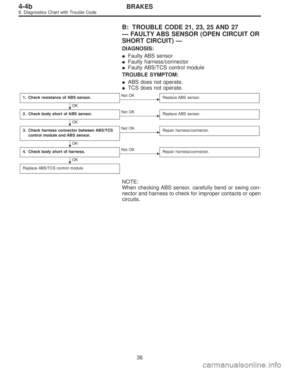
B: TROUBLE CODE 21, 23, 25 AND 27
—FAULTY ABS SENSOR (OPEN CIRCUIT OR
SHORT CIRCUIT)—
DIAGNOSIS:
�Faulty ABS sensor
�Faulty harness/connector
�Faulty ABS/TCS control module
TROUBLE SYMPTOM:
�ABS does not operate.
�TCS does not operate.
1. Check resistance of ABS sensor.
OK
�Not OK
Replace ABS sensor.
2. Check body short of ABS sensor.
OK
�Not OK
Replace ABS sensor.
3. Check harness connector between ABS/TCS
control module and ABS sensor.
OK
�Not OK
Repair harness/connector.
4. Check body short of harness.
OK
�Not OK
Repair harness/connector.
Replace ABS/TCS control module.
NOTE:
When checking ABS sensor, carefully bend or swing con-
nector and harness to check for improper contacts or open
circuits.
�
�
�
�
36
4-4bBRAKES
8. Diagnostics Chart with Trouble Code
Page 2513 of 3342
B4M0406
B4M0407A
1. CHECK RESISTANCE OF ABS SENSOR.
1) Turn ignition switch OFF.
2) Disconnect connector from ABS sensor.
3) Measure resistance between ABS sensor connector ter-
minals.
TROUBLE CODE / Connector & terminal:
21 / (B6) No. 1—No. 2
23 / (B15) No. 1—No. 2
25 / (P8) No. 1—No. 2
27 / (P9) No. 1—No. 2
Specified resistance: 0.8—1.2 kΩ
37
4-4bBRAKES
8. Diagnostics Chart with Trouble Code
Page 2514 of 3342
B4M0408A
2. CHECK BODY SHORT OF ABS SENSOR.
1) Turn ignition switch OFF.
2) Disconnect connector from ABS sensor.
3) Measure resistance between ABS sensor connector ter-
minal and body.
TROUBLE CODE / Connector & terminal:
21 / (B6) No. 1—body
/ (B6) No. 2—body
23 / (B15) No. 1—body
/ (B15) No. 2—body
25 / (P8) No. 1—body
/ (P8) No. 2—body
27 / (P9) No. 1—body
/ (P9) No. 2—body
Specified resistance: 1 MΩor more
B4M0409A
3. CHECK HARNESS CONNECTOR BETWEEN ABS/
TCS CONTROL MODULE AND ABS SENSOR.
1) Turn ignition switch OFF.
2) Connect connector to ABS sensor.
3) Disconnect all connectors from ABS/TCS control mod-
ule.
4) Measure resistance between ABS/TCS control module
connector terminals.
TROUBLE CODE / Connector & terminal:
21 / (P6) No. 8—No. 16
23 / (P7) No. 1—No. 11
25 / (P7) No. 2—No. 12
27 / (P6) No. 7—No. 15
Specified resistance: 0.8—1.2 kΩ
38
4-4bBRAKES
8. Diagnostics Chart with Trouble Code
Page 2515 of 3342
B4M0410A
4. CHECK BODY SHORT OF HARNESS.
1) Turn ignition switch OFF.
2) Connect connector to ABS sensor.
3) Disconnect all connectors from ABS/TCS control mod-
ule.
4) Measure resistance between ABS/TCS control module
connector terminals.
TROUBLE CODE / Connector & terminal:
21 / (P6) No. 8—body
/ (P6) No. 16—body
23 / (P7) No. 1—body
/ (P7) No. 11—body
25 / (P7) No. 2—body
/ (P7) No. 12—body
27 / (P6) No. 7—body
/ (P6) No. 15—body
Specified resistance: 1 MΩor more
39
4-4bBRAKES
8. Diagnostics Chart with Trouble Code
Page 2516 of 3342
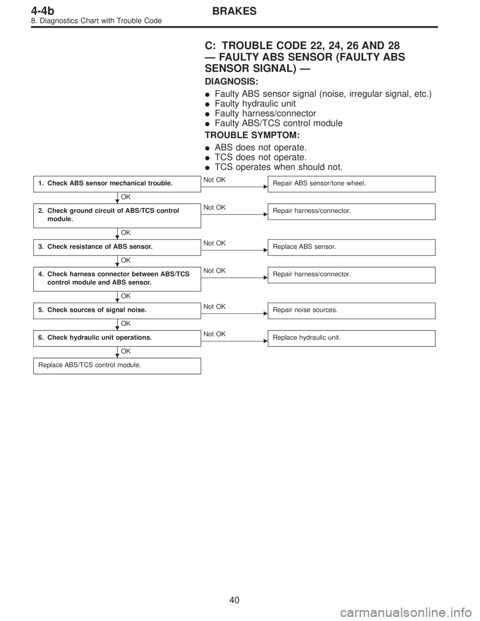
C: TROUBLE CODE 22, 24, 26 AND 28
—FAULTY ABS SENSOR (FAULTY ABS
SENSOR SIGNAL)—
DIAGNOSIS:
�Faulty ABS sensor signal (noise, irregular signal, etc.)
�Faulty hydraulic unit
�Faulty harness/connector
�Faulty ABS/TCS control module
TROUBLE SYMPTOM:
�ABS does not operate.
�TCS does not operate.
�TCS operates when should not.
1. Check ABS sensor mechanical trouble.
OK
�Not OK
Repair ABS sensor/tone wheel.
2. Check ground circuit of ABS/TCS control
module.
OK
�Not OK
Repair harness/connector.
3. Check resistance of ABS sensor.
OK
�Not OK
Replace ABS sensor.
4. Check harness connector between ABS/TCS
control module and ABS sensor.
OK
�Not OK
Repair harness/connector.
5. Check sources of signal noise.
OK
�Not OK
Repair noise sources.
6. Check hydraulic unit operations.
OK
�Not OK
Replace hydraulic unit.
Replace ABS/TCS control module.
�
�
�
�
�
�
40
4-4bBRAKES
8. Diagnostics Chart with Trouble Code

 Turn ignition switch OFF.
2) Disconnect conne")
 Turn ignition switch OFF.
2) Disconnect connector from ABS sensor.
3) Measure resistance between ABS sensor connector ter-
minals.
TROUBLE CODE /")
 Turn ignition switch OFF.
2) Disconnect connector from ABS sensor.
3) Measure resistance between ABS sensor connector ter-
minal and body.
TROUBLE CODE /")
 Turn ignition switch OFF.
2) Connect connector to ABS sensor.
3) Disconnect all connectors from ABS/TCS control mod-
ule.
4) Measure resistance between ABS/")