1997 SSANGYONG KORANDO air condition
[x] Cancel search: air conditionPage 1139 of 2053
5A-44 AUTOMATIC TRANSMISSION
SSANGYONG MY2002
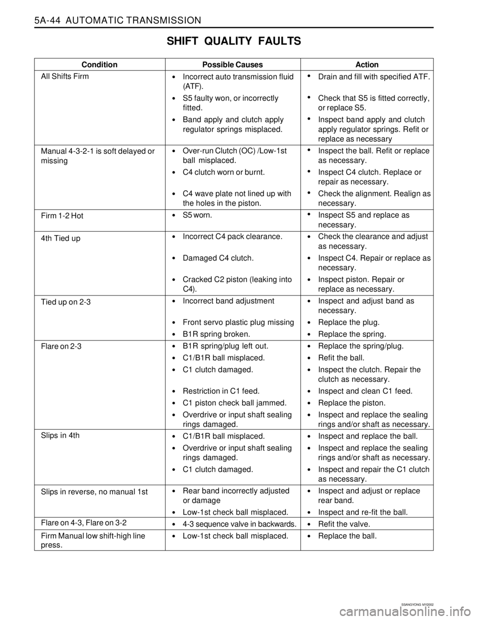
SHIFT QUALITY FAULTS
Condition Possible Causes
Incorrect auto transmission fluid
(ATF).
S5 faulty won, or incorrectly
fitted.
Band apply and clutch apply
regulator springs misplaced.
Over-run Clutch (OC) /Low-1st
ball misplaced.
C4 clutch worn or burnt.
C4 wave plate not lined up with
the holes in the piston.
S5 worn.
Incorrect C4 pack clearance.
Damaged C4 clutch.
Cracked C2 piston (leaking into
C4).
Incorrect band adjustment
Front servo plastic plug missing
B1R spring broken.
B1R spring/plug left out.
C1/B1R ball misplaced.
C1 clutch damaged.
Restriction in C1 feed.
C1 piston check ball jammed.
Overdrive or input shaft sealing
rings damaged.
C1/B1R ball misplaced.
Overdrive or input shaft sealing
rings damaged.
C1 clutch damaged.
Rear band incorrectly adjusted
or damage
Low-1st check ball misplaced.
4-3 sequence valve in backwards.
Low-1st check ball misplaced.Action
Drain and fill with specified ATF.
Check that S5 is fitted correctly,
or replace S5.
Inspect band apply and clutch
apply regulator springs. Refit or
replace as necessary
Inspect the ball. Refit or replace
as necessary.
Inspect C4 clutch. Replace or
repair as necessary.
Check the alignment. Realign as
necessary.
Inspect S5 and replace as
necessary.
Check the clearance and adjust
as necessary.
Inspect C4. Repair or replace as
necessary.
Inspect piston. Repair or
replace as necessary.
Inspect and adjust band as
necessary.
Replace the plug.
Replace the spring.
Replace the spring/plug.
Refit the ball.
Inspect the clutch. Repair the
clutch as necessary.
Inspect and clean C1 feed.
Replace the piston.
Inspect and replace the sealing
rings and/or shaft as necessary.
Inspect and replace the ball.
Inspect and replace the sealing
rings and/or shaft as necessary.
Inspect and repair the C1 clutch
as necessary.
Inspect and adjust or replace
rear band.
Inspect and re-fit the ball.
Refit the valve.
Replace the ball.
Manual 4-3-2-1 is soft delayed or
missing
Firm 1-2 Hot
4th Tied up
Tied up on 2-3
Flare on 2-3
Slips in 4th
Flare on 4-3, Flare on 3-2
Firm Manual low shift-high line
press.
Slips in reverse, no manual 1st
All Shifts Firm
Page 1140 of 2053
AUTOMATIC TRANSMISSION 5A-45
SSANGYONG MY2002
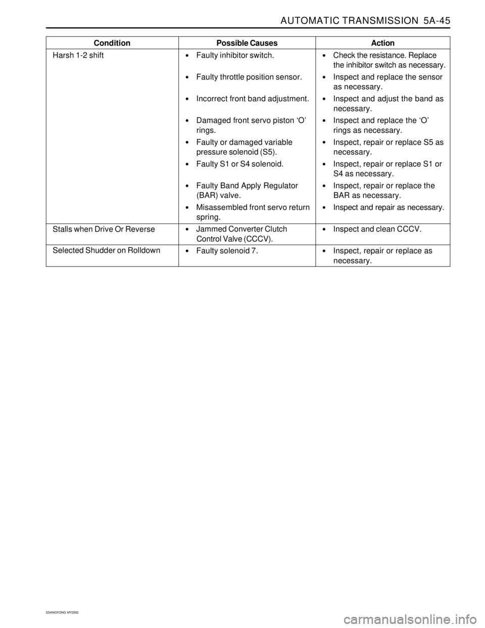
Condition
Harsh 1-2 shiftPossible Causes
Faulty inhibitor switch.
Faulty throttle position sensor.
Incorrect front band adjustment.
Damaged front servo piston ‘O’
rings.
Faulty or damaged variable
pressure solenoid (S5).
Faulty S1 or S4 solenoid.
Faulty Band Apply Regulator
(BAR) valve.
Misassembled front servo return
spring.
Jammed Converter Clutch
Control Valve (CCCV).
Faulty solenoid 7.Action
Check the resistance. Replace
the inhibitor switch as necessary.
Inspect and replace the sensor
as necessary.
Inspect and adjust the band as
necessary.
Inspect and replace the ‘O’
rings as necessary.
Inspect, repair or replace S5 as
necessary.
Inspect, repair or replace S1 or
S4 as necessary.
Inspect, repair or replace the
BAR as necessary.
Inspect and repair as necessary.
Inspect and clean CCCV.
Inspect, repair or replace as
necessary.
Stalls when Drive Or Reverse
Selected Shudder on Rolldown
Page 1141 of 2053
5A-46 AUTOMATIC TRANSMISSION
SSANGYONG MY2002
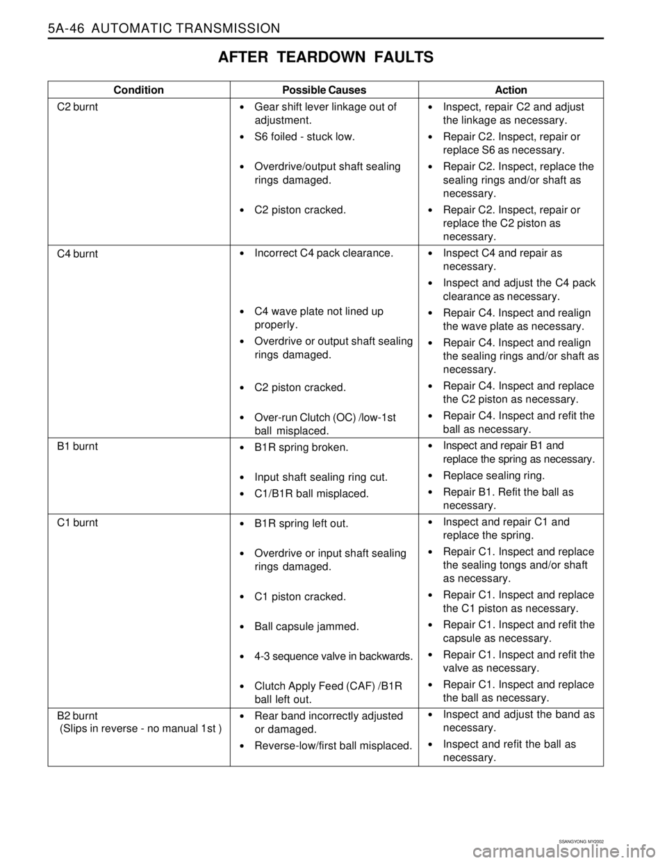
AFTER TEARDOWN FAULTS
Condition
C2 burntPossible Causes
Gear shift lever linkage out of
adjustment.
S6 foiled - stuck low.
Overdrive/output shaft sealing
rings damaged.
C2 piston cracked.
Incorrect C4 pack clearance.
C4 wave plate not lined up
properly.
Overdrive or output shaft sealing
rings damaged.
C2 piston cracked.
Over-run Clutch (OC) /low-1st
ball misplaced.
B1R spring broken.
Input shaft sealing ring cut.
C1/B1R ball misplaced.
B1R spring left out.
Overdrive or input shaft sealing
rings damaged.
C1 piston cracked.
Ball capsule jammed.
4-3 sequence valve in backwards.
Clutch Apply Feed (CAF) /B1R
ball left out.
Rear band incorrectly adjusted
or damaged.
Reverse-low/first ball misplaced.Action
Inspect, repair C2 and adjust
the linkage as necessary.
Repair C2. Inspect, repair or
replace S6 as necessary.
Repair C2. Inspect, replace the
sealing rings and/or shaft as
necessary.
Repair C2. Inspect, repair or
replace the C2 piston as
necessary.
Inspect C4 and repair as
necessary.
Inspect and adjust the C4 pack
clearance as necessary.
Repair C4. Inspect and realign
the wave plate as necessary.
Repair C4. Inspect and realign
the sealing rings and/or shaft as
necessary.
Repair C4. Inspect and replace
the C2 piston as necessary.
Repair C4. Inspect and refit the
ball as necessary.
Inspect and repair B1 and
replace the spring as necessary.
Replace sealing ring.
Repair B1. Refit the ball as
necessary.
Inspect and repair C1 and
replace the spring.
Repair C1. Inspect and replace
the sealing tongs and/or shaft
as necessary.
Repair C1. Inspect and replace
the C1 piston as necessary.
Repair C1. Inspect and refit the
capsule as necessary.
Repair C1. Inspect and refit the
valve as necessary.
Repair C1. Inspect and replace
the ball as necessary.
Inspect and adjust the band as
necessary.
Inspect and refit the ball as
necessary.
C4 burnt
B1 burnt
C1 burnt
B2 burnt
(Slips in reverse - no manual 1st )
Page 1143 of 2053
5A-48 AUTOMATIC TRANSMISSION
SSANGYONG MY2002
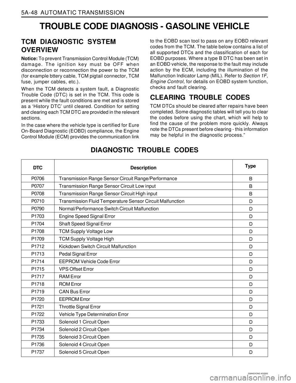
TROUBLE CODE DIAGNOSIS - GASOLINE VEHICLE
TCM DIAGNOSTIC SYSTEM
OVERVIEW
Notice: To prevent Transmission Control Module (TCM)
damage. The ignition key must be OFF when
disconnection or reconnection the power to the TCM
(for example bttery cable, TCM pigtail connector, TCM
fuse, jumper cables, etc.).
When the TCM detects a system fault, a Diagnostic
Trouble Code (DTC) is set in the TCM. This code is
present while the fault conditions are met and is stored
as a ‘History DTC’ until cleared. Condition for setting
and clearing each TCM DTC are provided in the relevant
sections.
In the case where the vehicle type is certified for Eure
On-Board Diagnostic (EOBD) compliance, the Engine
Control Module (ECM) provides the communication linkto the EOBD scan tool to pass on any EOBD relevant
codes from the TCM. The table below contains a list of
all supported DTCs and the classification of each for
EOBD purposes. Where a type B DTC has been set in
an EOBD vehicle, the response to the fault may include
action by the ECM, including the illumination of the
Malfunction lndicator Lamp (MIL). Refer to Section 1F,
Engine Control, for details on EOBD system function,
checks and fault clearing.
CLEARING TROUBLE CODES
TCM DTCs should be cleared after repairs have been
completed. Some diagnostic tables will tell you to clear
the codes before using the chart, which will help to
find the cause of the problem more quickly. Always
note the DTCs present before clearing - this information
may be helpful in the diagnostic process.”
DIAGNOSTIC TROUBLE CODES
DTC
P0706
P0707
P0708
P0710
P0790
P1703
P1704
P1708
P1709
P1712
P1713
P1714
P1715
P1717
P1718
P1719
P1720
P1721
P1722
P1733
P1734
P1735
P1736
P1737Type
B
B
B
D
D
D
D
D
D
D
D
D
D
D
D
D
D
D
D
D
D
D
D
D Description
Transmission Range Sensor Circuit Range/Performance
Transmission Range Sensor Circuit Low input
Transmission Range Sensor Circuit High input
Transmission Fluid Temperature Sensor Circuit Malfunction
Normal/Performance Switch Circuit Malfunction
Engine Speed Signal Error
Shaft Speed Signal Error
TCM Supply Voltage Low
TCM Supply Voltage High
Kickdown Switch Circuit Malfunction
Pedal Signal Error
EEPROM Vehicle Code Error
VPS Offset Error
RAM Error
ROM Error
CAN Bus Error
EEPROM Error
Throttle Signal Error
Vehicle Type Determination Error
Solenoid 1 Circuit Open
Solenoid 2 Circuit Open
Solenoid 3 Circuit Open
Solenoid 4 Circuit Open
Solenoid 5 Circuit Open
Page 1145 of 2053
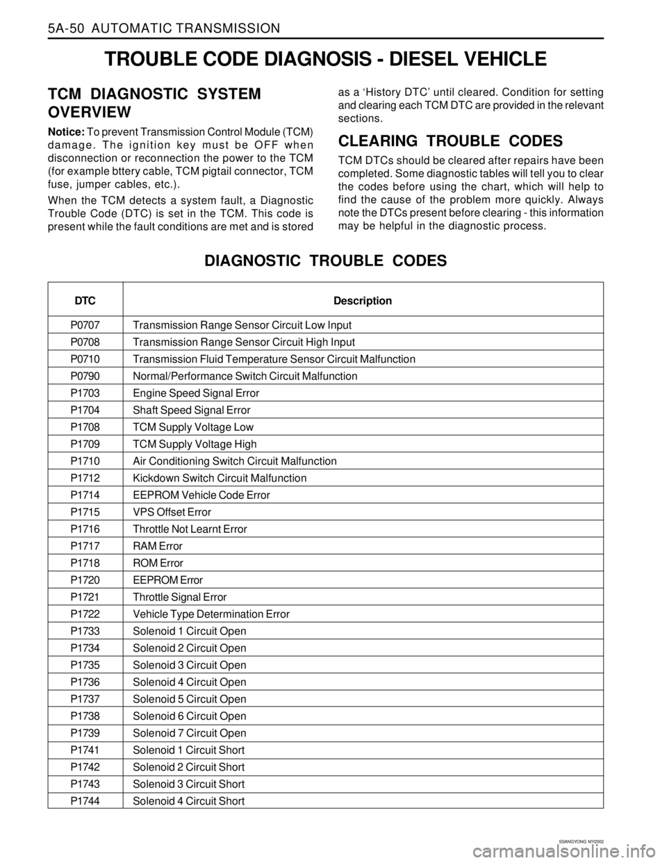
5A-50 AUTOMATIC TRANSMISSION
SSANGYONG MY2002
Transmission Range Sensor Circuit Low Input
Transmission Range Sensor Circuit High Input
Transmission Fluid Temperature Sensor Circuit Malfunction
Normal/Performance Switch Circuit Malfunction
Engine Speed Signal Error
Shaft Speed Signal Error
TCM Supply Voltage Low
TCM Supply Voltage High
Air Conditioning Switch Circuit Malfunction
Kickdown Switch Circuit Malfunction
EEPROM Vehicle Code Error
VPS Offset Error
Throttle Not Learnt Error
RAM Error
ROM Error
EEPROM Error
Throttle Signal Error
Vehicle Type Determination Error
Solenoid 1 Circuit Open
Solenoid 2 Circuit Open
Solenoid 3 Circuit Open
Solenoid 4 Circuit Open
Solenoid 5 Circuit Open
Solenoid 6 Circuit Open
Solenoid 7 Circuit Open
Solenoid 1 Circuit Short
Solenoid 2 Circuit Short
Solenoid 3 Circuit Short
Solenoid 4 Circuit Short
TROUBLE CODE DIAGNOSIS - DIESEL VEHICLE
TCM DIAGNOSTIC SYSTEM
OVERVIEW
Notice: To prevent Transmission Control Module (TCM)
damage. The ignition key must be OFF when
disconnection or reconnection the power to the TCM
(for example bttery cable, TCM pigtail connector, TCM
fuse, jumper cables, etc.).
When the TCM detects a system fault, a Diagnostic
Trouble Code (DTC) is set in the TCM. This code is
present while the fault conditions are met and is storedas a ‘History DTC’ until cleared. Condition for setting
and clearing each TCM DTC are provided in the relevant
sections.CLEARING TROUBLE CODES
TCM DTCs should be cleared after repairs have been
completed. Some diagnostic tables will tell you to clear
the codes before using the chart, which will help to
find the cause of the problem more quickly. Always
note the DTCs present before clearing - this information
may be helpful in the diagnostic process.
DIAGNOSTIC TROUBLE CODES
DTC
P0707
P0708
P0710
P0790
P1703
P1704
P1708
P1709
P1710
P1712
P1714
P1715
P1716
P1717
P1718
P1720
P1721
P1722
P1733
P1734
P1735
P1736
P1737
P1738
P1739
P1741
P1742
P1743
P1744Description
Page 1150 of 2053
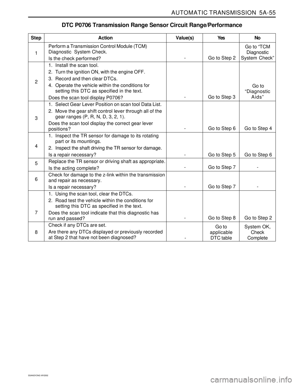
AUTOMATIC TRANSMISSION 5A-55
SSANGYONG MY2002
Perform a Transmission Control Module (TCM)
Diagnostic System Check.
Is the check performed?
1. Install the scan tool.
2. Turn the ignition ON, with the engine OFF.
3. Record and then clear DTCs.
4. Operate the vehicle within the conditions for
setting this DTC as specified in the text.
Does the scan tool display P0706?
1. Select Gear Lever Position on scan tool Data List.
2. Move the gear shift control lever through all of the
gear ranges (P, R, N, D, 3, 2, 1).
Does the scan tool display the correct gear lever
positions?
1. Inspect the TR sensor for damage to its rotating
part or its mountings.
2. Inspect the shaft driving the TR sensor for damage.
Is a repair necessary?
Replace the TR sensor or driving shaft as appropriate.
Is the acting complete?
Check for damage to the z-link within the transmission
and repair as necessary.
Is a repair necessary?
1. Using the scan tool, clear the DTCs.
2. Road test the vehicle within the conditions for
setting this DTC as specified in the text.
Does the scan tool indicate that this diagnostic has
run and passed?
Check if any DTCs are set.
Are there any DTCs displayed or previously recorded
at Step 2 that have not been diagnosed?
DTC P0706 Transmission Range Sensor Circuit Range/Performance
1
StepAction Value(s) Yes No
2
3
4
5
6
- Go to Step 2Go to “TCM
Diagnostic
System Check”
- Go to Step 6 Go to Step 4
- Go to Step 5 Go to Step 6
- Go to Step 7 -
8 7
- Go to Step 8 Go to Step 2
- Go to Step 7 -
- Go to Step 3 Go to
“Diagnostic
Aids”
-Go to
applicable
DTC tableSystem OK,
Check
Complete
Page 1152 of 2053
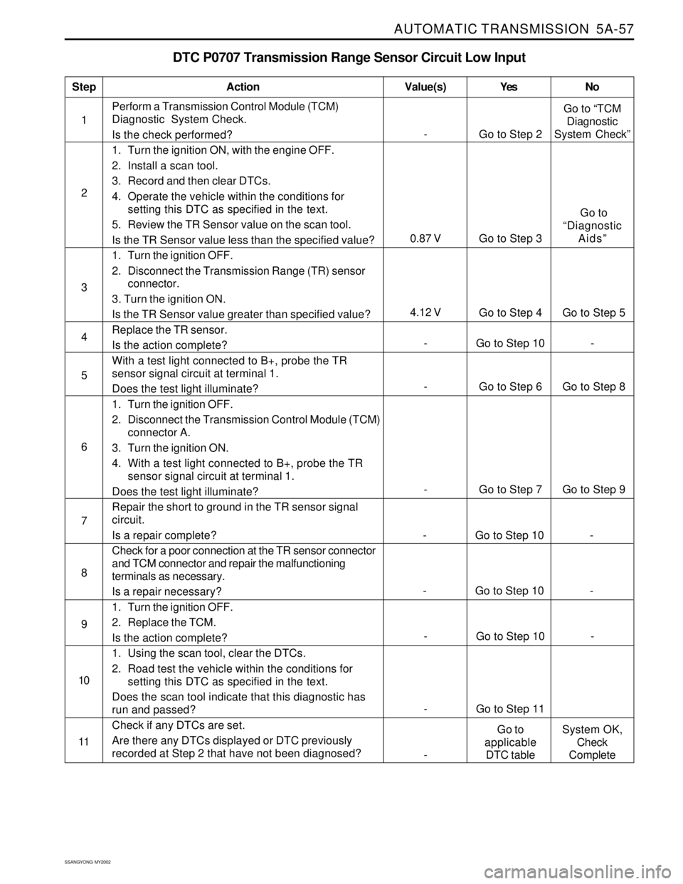
AUTOMATIC TRANSMISSION 5A-57
SSANGYONG MY2002
DTC P0707 Transmission Range Sensor Circuit Low Input
1Perform a Transmission Control Module (TCM)
Diagnostic System Check.
Is the check performed?
1. Turn the ignition ON, with the engine OFF.
2. Install a scan tool.
3. Record and then clear DTCs.
4. Operate the vehicle within the conditions for
setting this DTC as specified in the text.
5. Review the TR Sensor value on the scan tool.
Is the TR Sensor value less than the specified value?
1. Turn the ignition OFF.
2. Disconnect the Transmission Range (TR) sensor
connector.
3. Turn the ignition ON.
Is the TR Sensor value greater than specified value?
Replace the TR sensor.
Is the action complete?
With a test light connected to B+, probe the TR
sensor signal circuit at terminal 1.
Does the test light illuminate?
1. Turn the ignition OFF.
2. Disconnect the Transmission Control Module (TCM)
connector A.
3. Turn the ignition ON.
4. With a test light connected to B+, probe the TR
sensor signal circuit at terminal 1.
Does the test light illuminate?
Repair the short to ground in the TR sensor signal
circuit.
Is a repair complete?
Check for a poor connection at the TR sensor connector
and TCM connector and repair the malfunctioning
terminals as necessary.
Is a repair necessary?
1. Turn the ignition OFF.
2. Replace the TCM.
Is the action complete?
1. Using the scan tool, clear the DTCs.
2. Road test the vehicle within the conditions for
setting this DTC as specified in the text.
Does the scan tool indicate that this diagnostic has
run and passed?
Check if any DTCs are set.
Are there any DTCs displayed or DTC previously
recorded at Step 2 that have not been diagnosed?
StepAction Value(s) Yes No
2
3
- Go to Step 6 Go to Step 8 5
- Go to Step 7 Go to Step 9 6
- Go to Step 10 - 4
7
- Go to Step 10 - 8
- Go to Step 10 - 9
- Go to Step 11 10
11
- Go to Step 2Go to “TCM
Diagnostic
System Check”
4.12 V
Go to Step 4 Go to Step 5
0.87 V Go to Step 3 Go to
“Diagnostic
Aids”
-Go to
applicable
DTC tableSystem OK,
Check
Complete
- Go to Step 10 -
Page 1154 of 2053
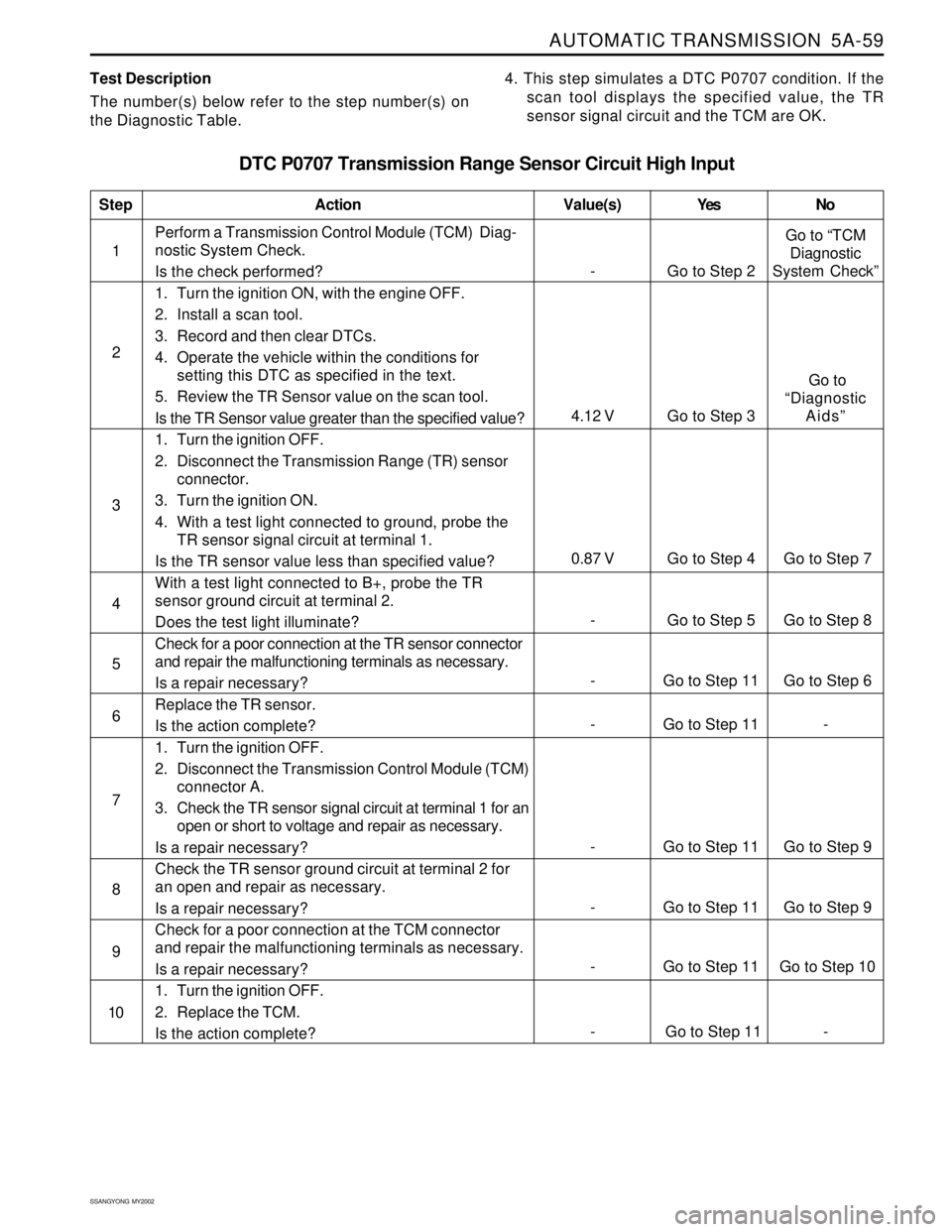
AUTOMATIC TRANSMISSION 5A-59
SSANGYONG MY2002
Test Description
The number(s) below refer to the step number(s) on
the Diagnostic Table.4. This step simulates a DTC P0707 condition. If the
scan tool displays the specified value, the TR
sensor signal circuit and the TCM are OK.
DTC P0707 Transmission Range Sensor Circuit High Input
1Perform a Transmission Control Module (TCM) Diag-
nostic System Check.
Is the check performed?
1. Turn the ignition ON, with the engine OFF.
2. Install a scan tool.
3. Record and then clear DTCs.
4. Operate the vehicle within the conditions for
setting this DTC as specified in the text.
5. Review the TR Sensor value on the scan tool.
Is the TR Sensor value greater than the specified value?
1. Turn the ignition OFF.
2. Disconnect the Transmission Range (TR) sensor
connector.
3. Turn the ignition ON.
4. With a test light connected to ground, probe the
TR sensor signal circuit at terminal 1.
Is the TR sensor value less than specified value?
With a test light connected to B+, probe the TR
sensor ground circuit at terminal 2.
Does the test light illuminate?
Check for a poor connection at the TR sensor connector
and repair the malfunctioning terminals as necessary.
Is a repair necessary?
Replace the TR sensor.
Is the action complete?
1. Turn the ignition OFF.
2. Disconnect the Transmission Control Module (TCM)
connector A.
3. Check the TR sensor signal circuit at terminal 1 for an
open or short to voltage and repair as necessary.
Is a repair necessary?
Check the TR sensor ground circuit at terminal 2 for
an open and repair as necessary.
Is a repair necessary?
Check for a poor connection at the TCM connector
and repair the malfunctioning terminals as necessary.
Is a repair necessary?
1. Turn the ignition OFF.
2. Replace the TCM.
Is the action complete?
StepAction Value(s) Yes No
2
3
- Go to Step 11 Go to Step 6 5
- Go to Step 11 - 6
- Go to Step 5 Go to Step 8 4
- Go to Step 11 Go to Step 9 7
- Go to Step 11 Go to Step 9 8
- Go to Step 11 Go to Step 10 9
10
- Go to Step 2Go to “TCM
Diagnostic
System Check”
0.87 V Go to Step 4 Go to Step 7
4.12 V Go to Step 3 Go to
“Diagnostic
Aids”
- Go to Step 11 -