1997 SSANGYONG KORANDO air condition
[x] Cancel search: air conditionPage 1060 of 2053
ABS AND TCS 4F-77
SSANGYONG MY2002
Step
1
2
3
4
5
6
7
8
9
10
11
12
13
14
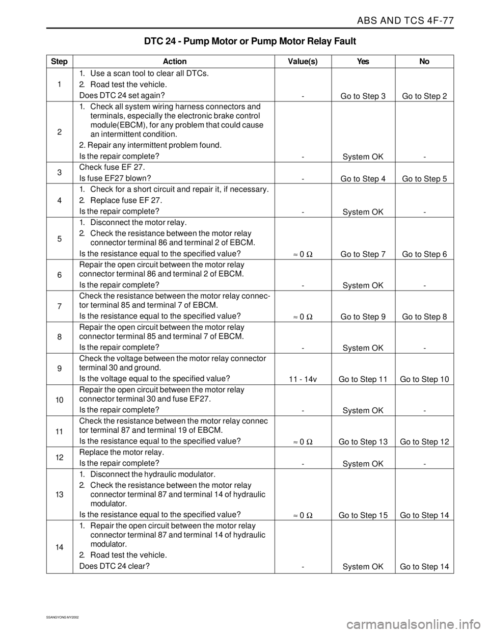
DTC 24 - Pump Motor or Pump Motor Relay Fault
Action
Go to Step 3
System OK
Go to Step 4
System OK
Go to Step 7
System OK
Go to Step 9
System OK
Go to Step 11
System OK
Go to Step 13
System OK
Go to Step 15
System OKGo to Step 2
-
Go to Step 5
-
Go to Step 6
-
Go to Step 8
-
Go to Step 10
-
Go to Step 12
-
Go to Step 14
Go to Step 14 -
-
-
-
≈ 0 Ω
-
≈ 0 Ω
-
11 - 14v
-
≈ 0 Ω
-
≈ 0 Ω
-
1. Use a scan tool to clear all DTCs.
2. Road test the vehicle.
Does DTC 24 set again?
1. Check all system wiring harness connectors and
terminals, especially the electronic brake control
module(EBCM), for any problem that could cause
an intermittent condition.
2. Repair any intermittent problem found.
Is the repair complete?
Check fuse EF 27.
Is fuse EF27 blown?
1. Check for a short circuit and repair it, if necessary.
2. Replace fuse EF 27.
Is the repair complete?
1. Disconnect the motor relay.
2. Check the resistance between the motor relay
connector terminal 86 and terminal 2 of EBCM.
Is the resistance equal to the specified value?
Repair the open circuit between the motor relay
connector terminal 86 and terminal 2 of EBCM.
Is the repair complete?
Check the resistance between the motor relay connec-
tor terminal 85 and terminal 7 of EBCM.
Is the resistance equal to the specified value?
Repair the open circuit between the motor relay
connector terminal 85 and terminal 7 of EBCM.
Is the repair complete?
Check the voltage between the motor relay connector
terminal 30 and ground.
Is the voltage equal to the specified value?
Repair the open circuit between the motor relay
connector terminal 30 and fuse EF27.
Is the repair complete?
Check the resistance between the motor relay connec
tor terminal 87 and terminal 19 of EBCM.
Is the resistance equal to the specified value?
Replace the motor relay.
Is the repair complete?
1. Disconnect the hydraulic modulator.
2. Check the resistance between the motor relay
connector terminal 87 and terminal 14 of hydraulic
modulator.
Is the resistance equal to the specified value?
1. Repair the open circuit between the motor relay
connector terminal 87 and terminal 14 of hydraulic
modulator.
2. Road test the vehicle.
Does DTC 24 clear?
Value(s) Yes No
Page 1072 of 2053
ABS AND TCS 4F-89
SSANGYONG MY2002
Step
1
2
3
4
5
6
7
8
9
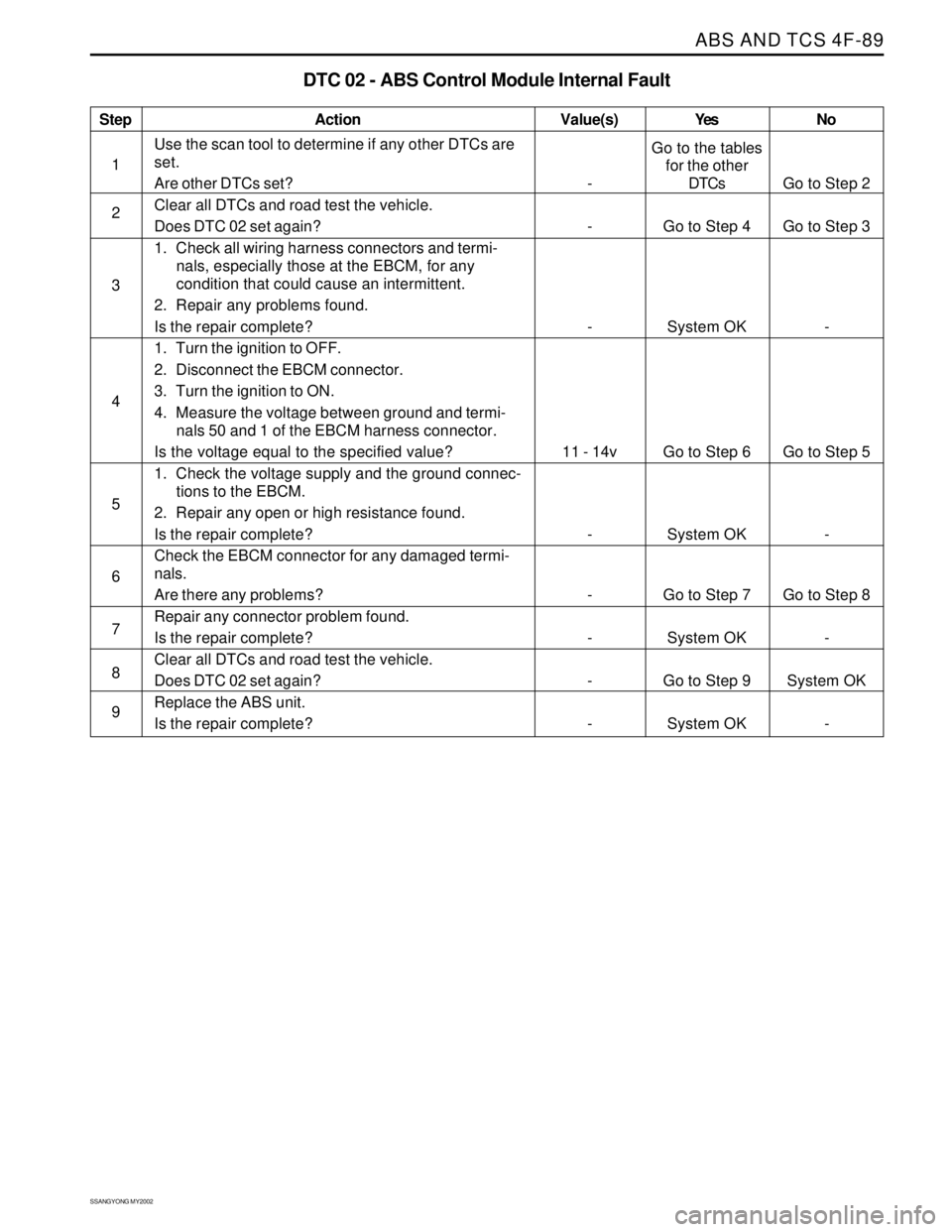
DTC 02 - ABS Control Module Internal Fault
Action
Go to the tables
for the other
DTCs
Go to Step 4
System OK
Go to Step 6
System OK
Go to Step 7
System OK
Go to Step 9
System OKGo to Step 2
Go to Step 3
-
Go to Step 5
-
Go to Step 8
-
System OK
- -
-
-
11 - 14v
-
-
-
-
-
Use the scan tool to determine if any other DTCs are
set.
Are other DTCs set?
Clear all DTCs and road test the vehicle.
Does DTC 02 set again?
1. Check all wiring harness connectors and termi-
nals, especially those at the EBCM, for any
condition that could cause an intermittent.
2. Repair any problems found.
Is the repair complete?
1. Turn the ignition to OFF.
2. Disconnect the EBCM connector.
3. Turn the ignition to ON.
4. Measure the voltage between ground and termi-
nals 50 and 1 of the EBCM harness connector.
Is the voltage equal to the specified value?
1. Check the voltage supply and the ground connec-
tions to the EBCM.
2. Repair any open or high resistance found.
Is the repair complete?
Check the EBCM connector for any damaged termi-
nals.
Are there any problems?
Repair any connector problem found.
Is the repair complete?
Clear all DTCs and road test the vehicle.
Does DTC 02 set again?
Replace the ABS unit.
Is the repair complete?
Value(s) Yes No
Page 1102 of 2053
5A-8 AUTOMATIC TRANSMISSION
SSANGYONG MY2002
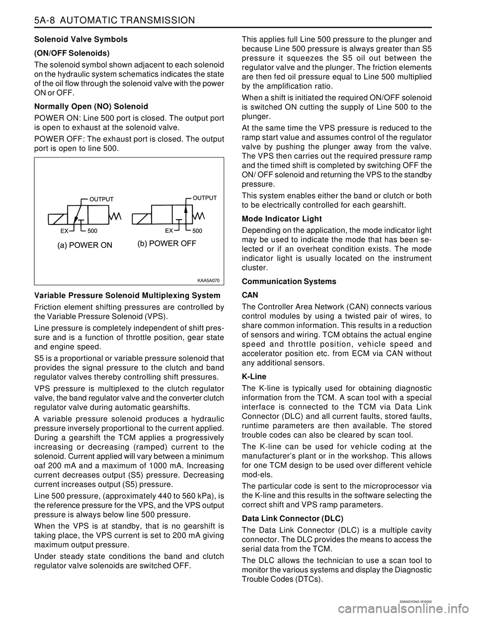
Solenoid Valve Symbols
(ON/OFF Solenoids)
The solenoid symbol shown adjacent to each solenoid
on the hydraulic system schematics indicates the state
of the oil flow through the solenoid valve with the power
ON or OFF.
Normally Open (NO) Solenoid
POWER ON: Line 500 port is closed. The output port
is open to exhaust at the solenoid valve.
POWER OFF: The exhaust port is closed. The output
port is open to line 500.
Variable Pressure Solenoid Multiplexing System
Friction element shifting pressures are controlled by
the Variable Pressure Solenoid (VPS).
Line pressure is completely independent of shift pres-
sure and is a function of throttle position, gear state
and engine speed.
S5 is a proportional or variable pressure solenoid that
provides the signal pressure to the clutch and band
regulator valves thereby controlling shift pressures.
VPS pressure is multiplexed to the clutch regulator
valve, the band regulator valve and the converter clutch
regulator valve during automatic gearshifts.
A variable pressure solenoid produces a hydraulic
pressure inversely proportional to the current applied.
During a gearshift the TCM applies a progressively
increasing or decreasing (ramped) current to the
solenoid. Current applied will vary between a minimum
oaf 200 mA and a maximum of 1000 mA. Increasing
current decreases output (S5) pressure. Decreasing
current increases output (S5) pressure.
Line 500 pressure, (approximately 440 to 560 kPa), is
the reference pressure for the VPS, and the VPS output
pressure is always below line 500 pressure.
When the VPS is at standby, that is no gearshift is
taking place, the VPS current is set to 200 mA giving
maximum output pressure.
Under steady state conditions the band and clutch
regulator valve solenoids are switched OFF.This applies full Line 500 pressure to the plunger and
because Line 500 pressure is always greater than S5
pressure it squeezes the S5 oil out between the
regulator valve and the plunger. The friction elements
are then fed oil pressure equal to Line 500 multiplied
by the amplification ratio.
When a shift is initiated the required ON/OFF solenoid
is switched ON cutting the supply of Line 500 to the
plunger.
At the same time the VPS pressure is reduced to the
ramp start value and assumes control of the regulator
valve by pushing the plunger away from the valve.
The VPS then carries out the required pressure ramp
and the timed shift is completed by switching OFF the
ON/ OFF solenoid and returning the VPS to the standby
pressure.
This system enables either the band or clutch or both
to be electrically controlled for each gearshift.
Mode Indicator Light
Depending on the application, the mode indicator light
may be used to indicate the mode that has been se-
lected or if an overheat condition exists. The mode
indicator light is usually located on the instrument
cluster.
Communication Systems
CAN
The Controller Area Network (CAN) connects various
control modules by using a twisted pair of wires, to
share common information. This results in a reduction
of sensors and wiring. TCM obtains the actual engine
speed and throttle position, vehicle speed and
accelerator position etc. from ECM via CAN without
any additional sensors.
K-Line
The K-line is typically used for obtaining diagnostic
information from the TCM. A scan tool with a special
interface is connected to the TCM via Data Link
Connector (DLC) and all current faults, stored faults,
runtime parameters are then available. The stored
trouble codes can also be cleared by scan tool.
The K-line can be used for vehicle coding at the
manufacturer’s plant or in the workshop. This allows
for one TCM design to be used over different vehicle
mod-els.
The particular code is sent to the microprocessor via
the K-line and this results in the software selecting the
correct shift and VPS ramp parameters.
Data Link Connector (DLC)
The Data Link Connector (DLC) is a multiple cavity
connector. The DLC provides the means to access the
serial data from the TCM.
The DLC allows the technician to use a scan tool to
monitor the various systems and display the Diagnostic
Trouble Codes (DTCs).
KAA5A070
Page 1134 of 2053
5A-40 AUTOMATIC TRANSMISSION
SSANGYONG MY2002
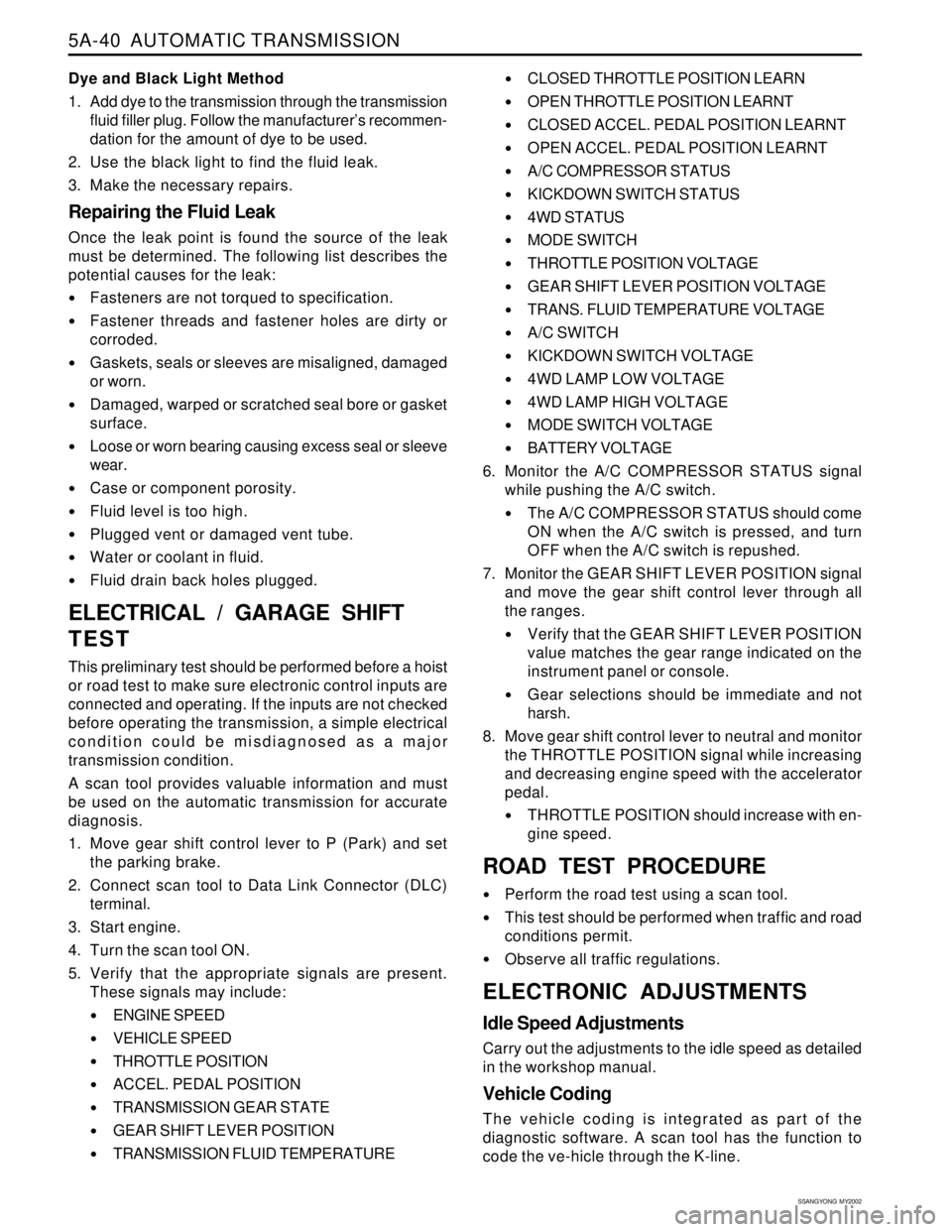
Dye and Black Light Method
1. Add dye to the transmission through the transmission
fluid filler plug. Follow the manufacturer’s recommen-
dation for the amount of dye to be used.
2. Use the black light to find the fluid leak.
3. Make the necessary repairs.
Repairing the Fluid Leak
Once the leak point is found the source of the leak
must be determined. The following list describes the
potential causes for the leak:
Fasteners are not torqued to specification.
Fastener threads and fastener holes are dirty or
corroded.
Gaskets, seals or sleeves are misaligned, damaged
or worn.
Damaged, warped or scratched seal bore or gasket
surface.
Loose or worn bearing causing excess seal or sleeve
wear.
Case or component porosity.
Fluid level is too high.
Plugged vent or damaged vent tube.
Water or coolant in fluid.
Fluid drain back holes plugged.
ELECTRICAL / GARAGE SHIFT
TEST
This preliminary test should be performed before a hoist
or road test to make sure electronic control inputs are
connected and operating. If the inputs are not checked
before operating the transmission, a simple electrical
condition could be misdiagnosed as a major
transmission condition.
A scan tool provides valuable information and must
be used on the automatic transmission for accurate
diagnosis.
1. Move gear shift control lever to P (Park) and set
the parking brake.
2. Connect scan tool to Data Link Connector (DLC)
terminal.
3. Start engine.
4. Turn the scan tool ON.
5. Verify that the appropriate signals are present.
These signals may include:
ENGINE SPEED
VEHICLE SPEED
THROTTLE POSITION
ACCEL. PEDAL POSITION
TRANSMISSION GEAR STATE
GEAR SHIFT LEVER POSITION
TRANSMISSION FLUID TEMPERATURE
CLOSED THROTTLE POSITION LEARN
OPEN THROTTLE POSITION LEARNT
CLOSED ACCEL. PEDAL POSITION LEARNT
OPEN ACCEL. PEDAL POSITION LEARNT
A/C COMPRESSOR STATUS
KICKDOWN SWITCH STATUS
4WD STATUS
MODE SWITCH
THROTTLE POSITION VOLTAGE
GEAR SHIFT LEVER POSITION VOLTAGE
TRANS. FLUID TEMPERATURE VOLTAGE
A/C SWITCH
KICKDOWN SWITCH VOLTAGE
4WD LAMP LOW VOLTAGE
4WD LAMP HIGH VOLTAGE
MODE SWITCH VOLTAGE
BATTERY VOLTAGE
6. Monitor the A/C COMPRESSOR STATUS signal
while pushing the A/C switch.
The A/C COMPRESSOR STATUS should come
ON when the A/C switch is pressed, and turn
OFF when the A/C switch is repushed.
7. Monitor the GEAR SHIFT LEVER POSITION signal
and move the gear shift control lever through all
the ranges.
Verify that the GEAR SHIFT LEVER POSITION
value matches the gear range indicated on the
instrument panel or console.
Gear selections should be immediate and not
harsh.
8. Move gear shift control lever to neutral and monitor
the THROTTLE POSITION signal while increasing
and decreasing engine speed with the accelerator
pedal.
THROTTLE POSITION should increase with en-
gine speed.
ROAD TEST PROCEDURE
Perform the road test using a scan tool.
This test should be performed when traffic and road
conditions permit.
Observe all traffic regulations.
ELECTRONIC ADJUSTMENTS
Idle Speed Adjustments
Carry out the adjustments to the idle speed as detailed
in the workshop manual.
Vehicle Coding
The vehicle coding is integrated as part of the
diagnostic software. A scan tool has the function to
code the ve-hicle through the K-line.
Page 1135 of 2053
5A-40 AUTOMATIC TRANSMISSION
SSANGYONG MY2002
Dye and Black Light Method
1. Add dye to the transmission through the transmission
fluid filler plug. Follow the manufacturer’s recommen-
dation for the amount of dye to be used.
2. Use the black light to find the fluid leak.
3. Make the necessary repairs.
Repairing the Fluid Leak
Once the leak point is found the source of the leak
must be determined. The following list describes the
potential causes for the leak:
Fasteners are not torqued to specification.
Fastener threads and fastener holes are dirty or
corroded.
Gaskets, seals or sleeves are misaligned, damaged
or worn.
Damaged, warped or scratched seal bore or gasket
surface.
Loose or worn bearing causing excess seal or sleeve
wear.
Case or component porosity.
Fluid level is too high.
Plugged vent or damaged vent tube.
Water or coolant in fluid.
Fluid drain back holes plugged.
ELECTRICAL / GARAGE SHIFT
TEST
This preliminary test should be performed before a hoist
or road test to make sure electronic control inputs are
connected and operating. If the inputs are not checked
before operating the transmission, a simple electrical
condition could be misdiagnosed as a major
transmission condition.
A scan tool provides valuable information and must
be used on the automatic transmission for accurate
diagnosis.
1. Move gear shift control lever to P (Park) and set
the parking brake.
2. Connect scan tool to Data Link Connector (DLC)
terminal.
3. Start engine.
4. Turn the scan tool ON.
5. Verify that the appropriate signals are present.
These signals may include:
ENGINE SPEED
VEHICLE SPEED
THROTTLE POSITION
ACCEL. PEDAL POSITION
TRANSMISSION GEAR STATE
GEAR SHIFT LEVER POSITION
TRANSMISSION FLUID TEMPERATURE
CLOSED THROTTLE POSITION LEARN
OPEN THROTTLE POSITION LEARNT
CLOSED ACCEL. PEDAL POSITION LEARNT
OPEN ACCEL. PEDAL POSITION LEARNT
A/C COMPRESSOR STATUS
KICKDOWN SWITCH STATUS
4WD STATUS
MODE SWITCH
THROTTLE POSITION VOLTAGE
GEAR SHIFT LEVER POSITION VOLTAGE
TRANS. FLUID TEMPERATURE VOLTAGE
A/C SWITCH
KICKDOWN SWITCH VOLTAGE
4WD LAMP LOW VOLTAGE
4WD LAMP HIGH VOLTAGE
MODE SWITCH VOLTAGE
BATTERY VOLTAGE
6. Monitor the A/C COMPRESSOR STATUS signal
while pushing the A/C switch.
The A/C COMPRESSOR STATUS should come
ON when the A/C switch is pressed, and turn
OFF when the A/C switch is repushed.
7. Monitor the GEAR SHIFT LEVER POSITION signal
and move the gear shift control lever through all
the ranges.
Verify that the GEAR SHIFT LEVER POSITION
value matches the gear range indicated on the
instrument panel or console.
Gear selections should be immediate and not
harsh.
8. Move gear shift control lever to neutral and monitor
the THROTTLE POSITION signal while increasing
and decreasing engine speed with the accelerator
pedal.
THROTTLE POSITION should increase with en-
gine speed.
ROAD TEST PROCEDURE
Perform the road test using a scan tool.
This test should be performed when traffic and road
conditions permit.
Observe all traffic regulations.
ELECTRONIC ADJUSTMENTS
Idle Speed Adjustments
Carry out the adjustments to the idle speed as detailed
in the workshop manual.
Vehicle Coding
The vehicle coding is integrated as part of the
diagnostic software. A scan tool has the function to
code the ve-hicle through the K-line.
Page 1136 of 2053
AUTOMATIC TRANSMISSION 5A-41
SSANGYONG MY2002
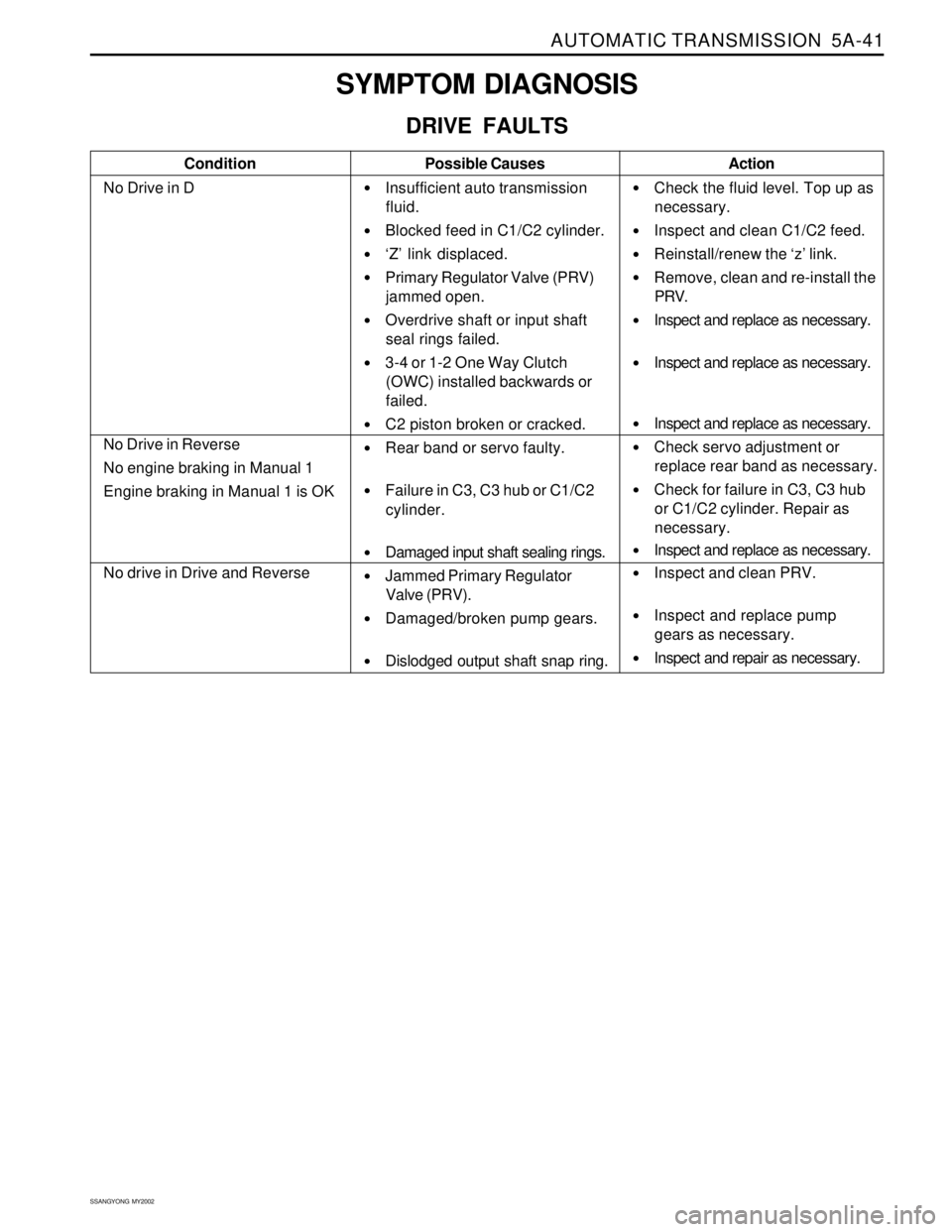
SYMPTOM DIAGNOSIS
DRIVE FAULTS
Condition
No Drive in DPossible Causes
Insufficient auto transmission
fluid.
Blocked feed in C1/C2 cylinder.
‘Z’ link displaced.
Primary Regulator Valve (PRV)
jammed open.
Overdrive shaft or input shaft
seal rings failed.
3-4 or 1-2 One Way Clutch
(OWC) installed backwards or
failed.
C2 piston broken or cracked.
Rear band or servo faulty.
Failure in C3, C3 hub or C1/C2
cylinder.
Damaged input shaft sealing rings.
Jammed Primary Regulator
Valve (PRV).
Damaged/broken pump gears.
Dislodged output shaft snap ring.Action
Check the fluid level. Top up as
necessary.
Inspect and clean C1/C2 feed.
Reinstall/renew the ‘z’ link.
Remove, clean and re-install the
PRV.
Inspect and replace as necessary.
Inspect and replace as necessary.
Inspect and replace as necessary.
Check servo adjustment or
replace rear band as necessary.
Check for failure in C3, C3 hub
or C1/C2 cylinder. Repair as
necessary.
Inspect and replace as necessary.
Inspect and clean PRV.
Inspect and replace pump
gears as necessary.
Inspect and repair as necessary.
No Drive in Reverse
No engine braking in Manual 1
Engine braking in Manual 1 is OK
No drive in Drive and Reverse
Page 1137 of 2053
5A-42 AUTOMATIC TRANSMISSION
SSANGYONG MY2002
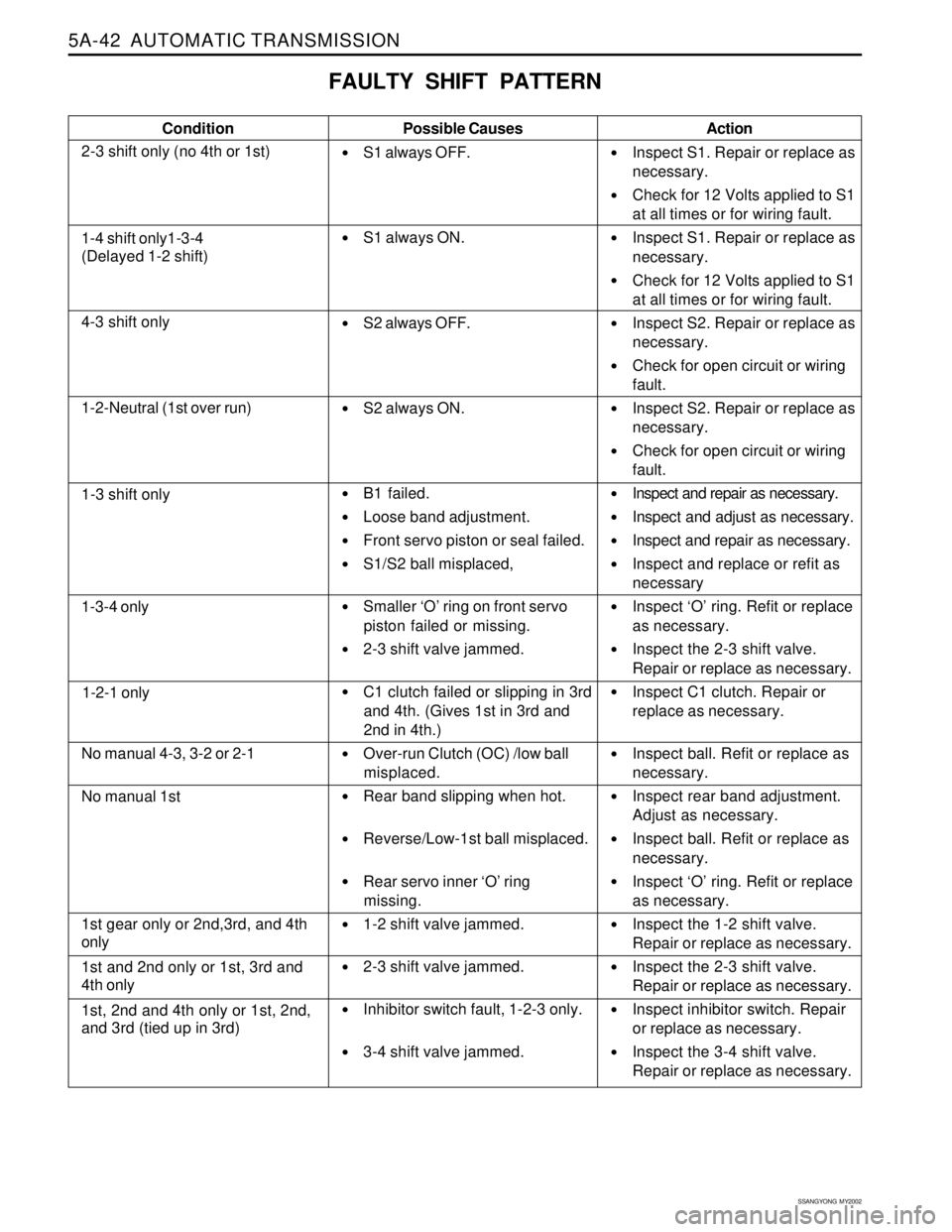
FAULTY SHIFT PATTERN
Condition
2-3 shift only (no 4th or 1st)Possible Causes
S1 always OFF.
S1 always ON.
S2 always OFF.
S2 always ON.
B1 failed.
Loose band adjustment.
Front servo piston or seal failed.
S1/S2 ball misplaced,
Smaller ‘O’ ring on front servo
piston failed or missing.
2-3 shift valve jammed.
C1 clutch failed or slipping in 3rd
and 4th. (Gives 1st in 3rd and
2nd in 4th.)
Over-run Clutch (OC) /low ball
misplaced.
Rear band slipping when hot.
Reverse/Low-1st ball misplaced.
Rear servo inner ‘O’ ring
missing.
1-2 shift valve jammed.
2-3 shift valve jammed.
Inhibitor switch fault, 1-2-3 only.
3-4 shift valve jammed.Action
Inspect S1. Repair or replace as
necessary.
Check for 12 Volts applied to S1
at all times or for wiring fault.
Inspect S1. Repair or replace as
necessary.
Check for 12 Volts applied to S1
at all times or for wiring fault.
Inspect S2. Repair or replace as
necessary.
Check for open circuit or wiring
fault.
Inspect S2. Repair or replace as
necessary.
Check for open circuit or wiring
fault.
Inspect and repair as necessary.
Inspect and adjust as necessary.
Inspect and repair as necessary.
Inspect and replace or refit as
necessary
Inspect ‘O’ ring. Refit or replace
as necessary.
Inspect the 2-3 shift valve.
Repair or replace as necessary.
Inspect C1 clutch. Repair or
replace as necessary.
Inspect ball. Refit or replace as
necessary.
Inspect rear band adjustment.
Adjust as necessary.
Inspect ball. Refit or replace as
necessary.
Inspect ‘O’ ring. Refit or replace
as necessary.
Inspect the 1-2 shift valve.
Repair or replace as necessary.
Inspect the 2-3 shift valve.
Repair or replace as necessary.
Inspect inhibitor switch. Repair
or replace as necessary.
Inspect the 3-4 shift valve.
Repair or replace as necessary.
1-4 shift only1-3-4
(Delayed 1-2 shift)
4-3 shift only
1-2-Neutral (1st over run)
1-3 shift only
1-3-4 only
1-2-1 only
No manual 4-3, 3-2 or 2-1
No manual 1st
1st gear only or 2nd,3rd, and 4th
only
1st and 2nd only or 1st, 3rd and
4th only
1st, 2nd and 4th only or 1st, 2nd,
and 3rd (tied up in 3rd)
Page 1138 of 2053
AUTOMATIC TRANSMISSION 5A-43
SSANGYONG MY2002
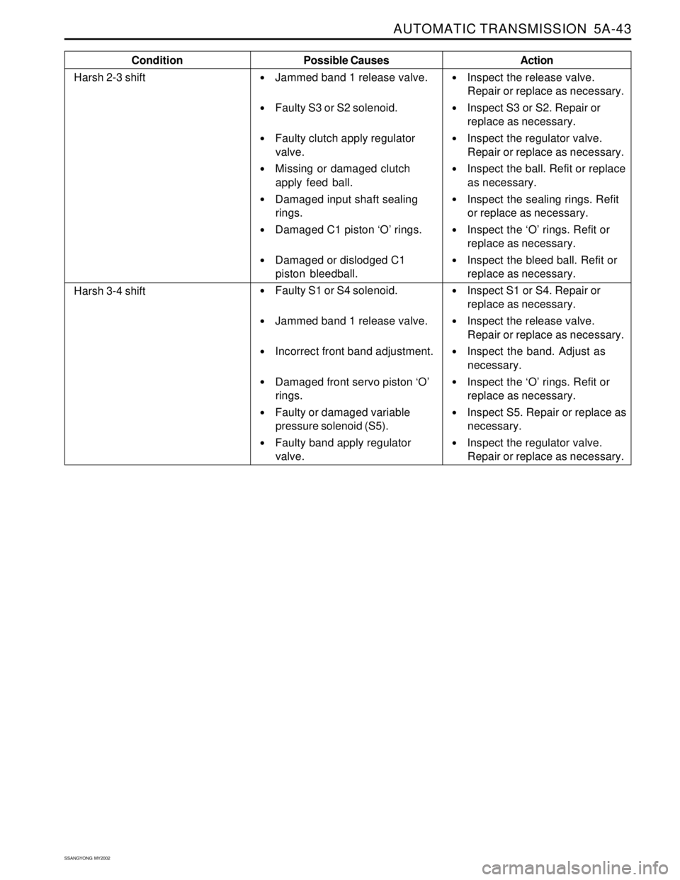
Condition
Harsh 2-3 shiftPossible Causes
Jammed band 1 release valve.
Faulty S3 or S2 solenoid.
Faulty clutch apply regulator
valve.
Missing or damaged clutch
apply feed ball.
Damaged input shaft sealing
rings.
Damaged C1 piston ‘O’ rings.
Damaged or dislodged C1
piston bleedball.
Faulty S1 or S4 solenoid.
Jammed band 1 release valve.
Incorrect front band adjustment.
Damaged front servo piston ‘O’
rings.
Faulty or damaged variable
pressure solenoid (S5).
Faulty band apply regulator
valve.Action
Inspect the release valve.
Repair or replace as necessary.
Inspect S3 or S2. Repair or
replace as necessary.
Inspect the regulator valve.
Repair or replace as necessary.
Inspect the ball. Refit or replace
as necessary.
Inspect the sealing rings. Refit
or replace as necessary.
Inspect the ‘O’ rings. Refit or
replace as necessary.
Inspect the bleed ball. Refit or
replace as necessary.
Inspect S1 or S4. Repair or
replace as necessary.
Inspect the release valve.
Repair or replace as necessary.
Inspect the band. Adjust as
necessary.
Inspect the ‘O’ rings. Refit or
replace as necessary.
Inspect S5. Repair or replace as
necessary.
Inspect the regulator valve.
Repair or replace as necessary.
Harsh 3-4 shift