1997 SSANGYONG KORANDO tow
[x] Cancel search: towPage 1575 of 2053
FATC-HAVC 7D-21
SSANGYONG MY2002
KAA7D310
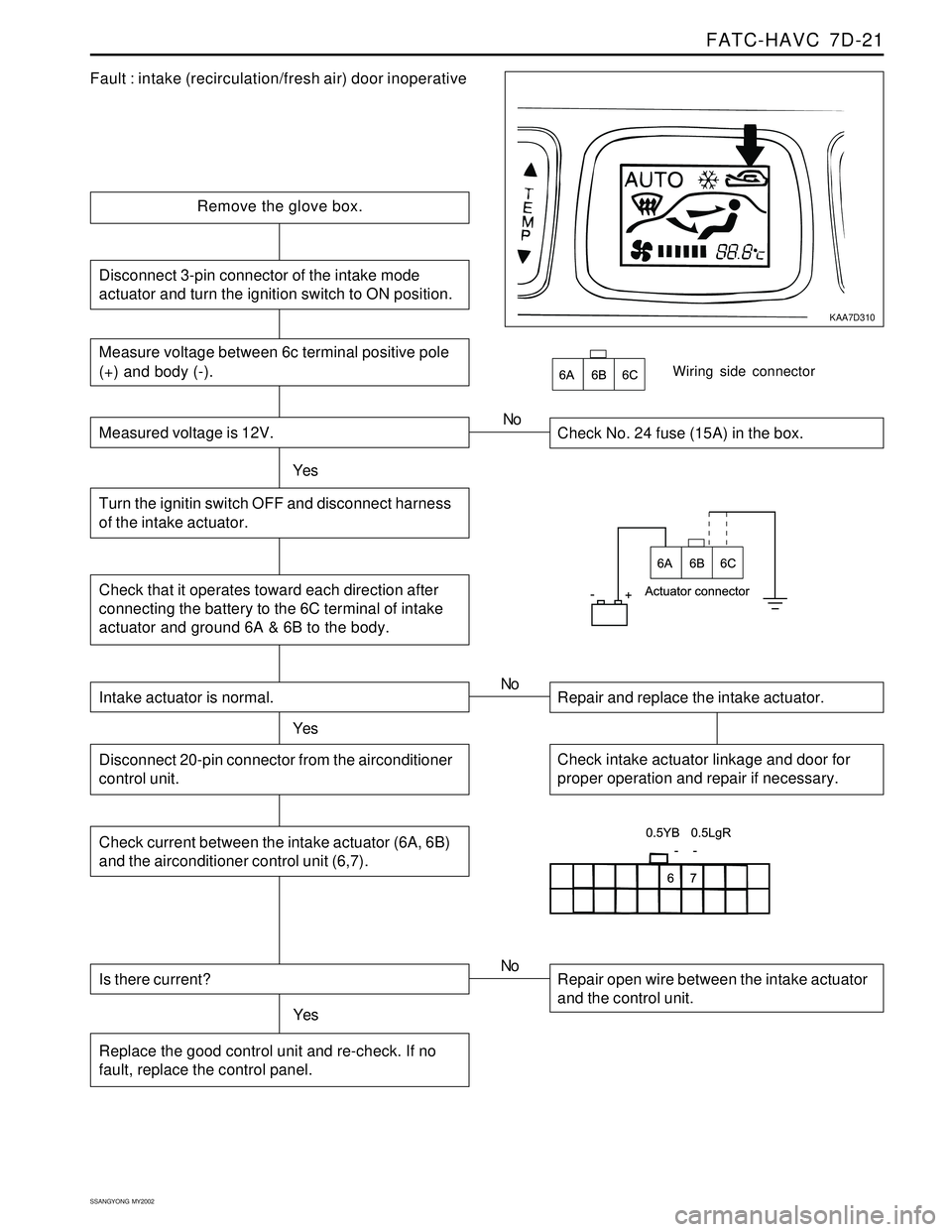
Fault : intake (recirculation/fresh air) door inoperative
Remove the glove box.
Check No. 24 fuse (15A) in the box.
YesNo
Check that it operates toward each direction after
connecting the battery to the 6C terminal of intake
actuator and ground 6A & 6B to the body.
Wiring side connector
Intake actuator is normal.
YesRepair and replace the intake actuator. No
Check intake actuator linkage and door for
proper operation and repair if necessary.Disconnect 20-pin connector from the airconditioner
control unit.
Check current between the intake actuator (6A, 6B)
and the airconditioner control unit (6,7).
Is there current?
YesRepair open wire between the intake actuator
and the control unit. No
Replace the good control unit and re-check. If no
fault, replace the control panel.
Measure voltage between 6c terminal positive pole
(+) and body (-).
Measured voltage is 12V.
Turn the ignitin switch OFF and disconnect harness
of the intake actuator.
Disconnect 3-pin connector of the intake mode
actuator and turn the ignition switch to ON position.
Page 1576 of 2053
SSANGYONG MY2002
7D-22 FATC-HAVC
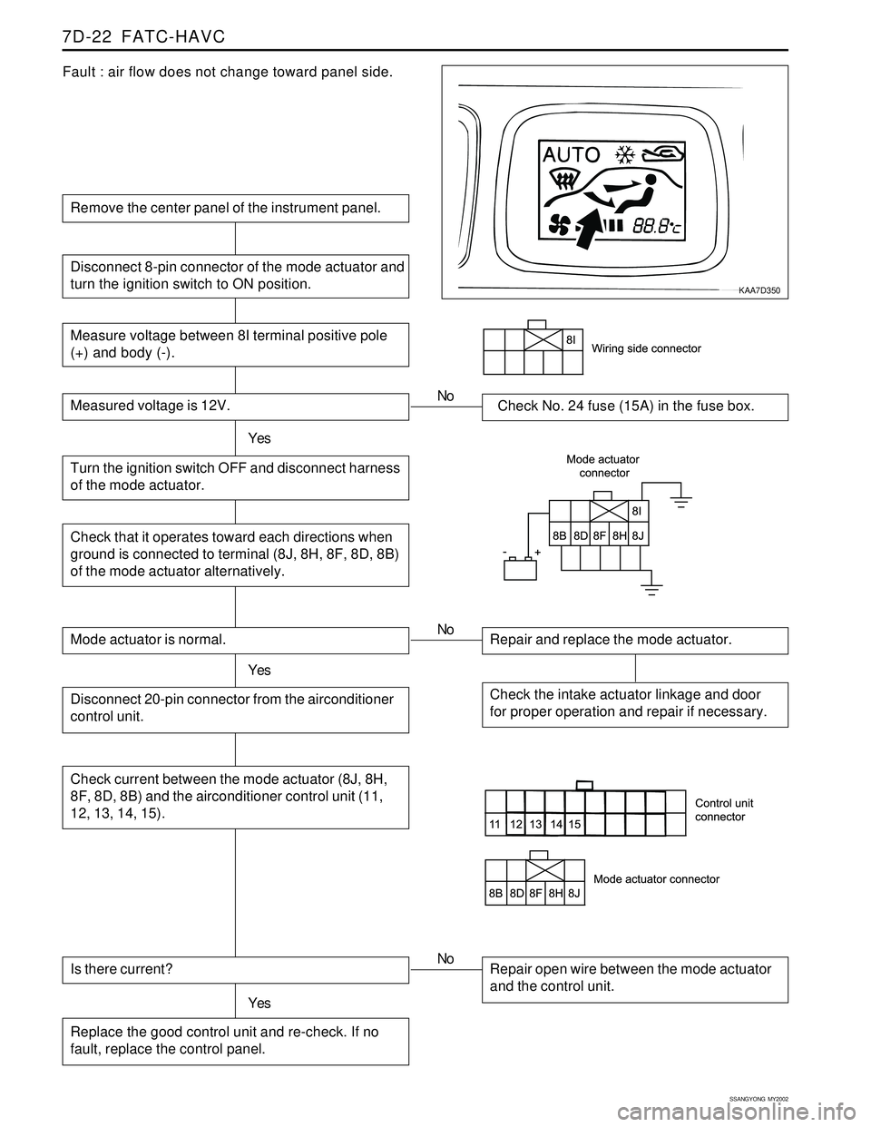
Fault : air flow does not change toward panel side.
Remove the center panel of the instrument panel.
Measure voltage between 8I terminal positive pole
(+) and body (-).
Measured voltage is 12V.Check No. 24 fuse (15A) in the fuse box.
Turn the ignition switch OFF and disconnect harness
of the mode actuator.YesNo
Disconnect 8-pin connector of the mode actuator and
turn the ignition switch to ON position.
Check that it operates toward each directions when
ground is connected to terminal (8J, 8H, 8F, 8D, 8B)
of the mode actuator alternatively.
Mode actuator is normal.
YesRepair and replace the mode actuator. No
Check the intake actuator linkage and door
for proper operation and repair if necessary.Disconnect 20-pin connector from the airconditioner
control unit.
Check current between the mode actuator (8J, 8H,
8F, 8D, 8B) and the airconditioner control unit (11,
12, 13, 14, 15).
Is there current?
YesRepair open wire between the mode actuator
and the control unit. No
Replace the good control unit and re-check. If no
fault, replace the control panel.
KAA7D350
Page 1642 of 2053

SSANGYONG MY2002
8B-60 SUPPLEMENTAL RESTRAINTS SYSTEM
KAA8B140
DRIVER AIRBAG MODULE
Removal and installation Procedure
1. Disconnect the negative battery cable.
Caution: The SDM can maintain sufficient
voltage to deploy the airbags for 0.15 seconds
after the Ignition is OFF and the airbag fuse has
been removed. If the airbags are not
disconnected, service cannot begin until one
minute has passed after disconnecting power
to the SDM. If the airbags are disconnected,
service can begin immediately without waiting
for one-minute time period to expire. Failure to
temporarily disable the SRS during service
result in unexpected deployment, personal
injury, and otherwise unneeded SRS repair.
2. Disable the supplemental restraint system (SRS).
Refer to “Disabling the SRS” in this section.
3. Position the steering wheel straight ahead.
4. Remove the driver airbag module mounting bolts.
Installation Notice
Caution: When handling an airbag module,
always keeps the top of the unit facing upward.
This leaves room for the airbag to expand if the
module unexpectedly deploys. Without room
for expansion, a module suddenly propelled
toward a person or object can cause injury or
vehicle damage.
5. Remove the connector from the horn terminal and
the driver airbag module.
6. Remove the driver airbag module.
7. Installation should follow the removal procedure
in the reverse order.
Tightening Torque 8 Nm (71 lb-in)
Page 1676 of 2053
SSANGYONG MY2002
9B-2 LIGHTING SYSTEM
DESCRIPTION AND OPERATION
HEAD LAMPS - ON REMINDER
When the headlamp switch is in the headlamps-on or
parkinglamps-on positions, voltage is applied to the
chime module. With the headlamp switch on and the
driver’s side door open, the module loses voltage. The
module senses this change. If voltage is still available,
it is applied to sound the chime. The chime can be
turned off by turning the headlamp switch off or closing
the driver’s side door. To replace the chime module,
refer to Section 9E, Instrumentation / Driver Information.
HEAD LAMPS
The headlamps are controlled by the multifunction lever
on the left side of the steering column. They will come
on with the ignition switch in on position. Turning the
headlamp switch to the first position turns on the
parking lamps, the license plate lamps, and the
instrument panel illumination. Turning the switch to the
second position turns on all of the previous lamps and
the headlamps. Turning the switch off turns off all the
lamps.
The headlamps high beam and low beams are also
controlled by this lever. When the headlamps are on,
pushing the lever away from the driver until the switch
clicks changes the lamp from low beam to high beam.
An indicator lamp on the instrument cluster assembly
will come on when the high beam headlamps are on.
To return the headlamps to low beams, pull the lever
toward the driver.
The headlamps must be aimed for proper illumination
of the road. Headlamp aim should be checked
whenever a new headlamp assembly is installed or
when service or repairs to the front end may have
disturbed the headlamp assembly or its mountings.
DAYTIME RUNNING LAMPS
The daytime running lamps (DRL) will illuminate under
the following conditions:
The ignition is ON.
The light switch is OFF.
The parking brake is released.
When the head lamps are on, the DRL will turn off.
To turn the DRL off when idling, apply the parking
brake.
PARKING AND TURN SIGNAL
LAMPS
The parking lamps can be turned on by turning the
headlamp switch to the first position. The parking lamps
can be turned off by turning the switch off.
When the turn signals are activated, the appropriate
turn signal lamps flash to signal a turn. The front, the
rear, work only when the ignition is on.
The front and rear turn signals are controlled by the
multifunction lever on the left side of the steering
column. Moving the lever all the way up or down past
the detent will turn on the turn signals. When the turn
is complete, the lever will automatically be release,
and the front and the rear turn signals will stop flashing.
For changing lanes or shallow turns in which the steering
wheel does not turn far enough to cancel the signal,
move the signal to the first detent and hold it there.
The turn signal will cancel when the lever is released.
FOG LAMPS
The fog lamp switch is located in multifunction lever
on the right side of steering column. To use the fog
lamps, first turn on the parking lamps. Then, turning
the fog lamps switch on position. The indicator light in
the instrument cluster will illuminate to indicate that
the fog lamps are on. Turning the switch again to turn
off the fog lamps. The indicator light will then go off.
The fog lamps must be aimed for proper illumination
of the road. Fog lamp aim should be checked when a
new bulb is installed or if service or repairs to the front
end may have disturbed the fog lamp assembly or its
mountings.
REAR COMBINATION LAMPS
The taillamps, stoplamps, backup lamps and turn
signals are one assembly.
Turning on either the headlamps or the parking lamps
will also turn on the taillamps. When the brake pedal
is pushed, the taillamps will glow more brightly to serve
as stop lamps.
CENTER HIGH-MOUNTED STOP
LAMP
The center high-mounted stoplamp is on the tail gate
and will come on when the brake pedal is pressed.
Page 1719 of 2053

SSANGYONG MY2002
9E-2 INSTRUMENTATION, DRIVER INFORMATION
DESCRIPTION AND OPERATION
CIGAR LIGHTER
The cigar lighter is located in the front portion of the
floor console. To use the lighter, push it in completely.
When the lighter is hot, it will release itsef from contact
with the heating element. The lighter and the heating
element can be damaged if the lighter does not fully
release itsef from the heating element.
ASHTRAY
The ashtray is located in the console. To access the
ashtray, pullit out of the ashtray housing. The ashtray
lamp will go on when the parking lamps or headlamps
are turned on.
INSTRUMENT PANEL VENTS
The center and the side vents in the instrument panel
can be adjusted up and down and from side to side.
The side vents can also be aimed toward the side
windows to defog them.
GLOVE BOX
The glove box can be opened by pulling upon the latch
handle.
DIGITAL CLOCK
The digital clock is located in the instrument cluster.
INSTRUMENT CLUSTER
The instrument cluster is located above the steering
column and in the instrument cluster trim panel. The
instrument cluster contains the instruments that
provide the driver with vehicle performance information.
The instrument cluster contains a speedometer, a
tachometer, an odometer, a trip odometer, a
temperature gauge, a fuel gauge, and several indicator
lamps. For replacement of the indicator lamp bulbs
contained in the instrument cluster, refer to “Instrument
Cluster Indicator Lamps Specifications” in the section.
SPEEDOMETER AND
TACHOMETER
The speedometer measures the speed of the vehicle
in km/h (with mph) or mph (with km/h). It consists of
an instrument cluster gauge connected to the vehicle
speed sensor on the transaxle output shaft. The
tachometer measures the engine’s speed in terms of
thousands of revolutions per minute. It consists of an
instrument cluster gauge connected to a sending unit
in the engine con-trol module. Do not operate the
engine in the red zone. Engine damage may occur.
TRIP ODOMETER
The trip odometer measures the distance the vehicle
has traveled since it was last reset. It consists of an
instrument cluster gauge connected to the sending unit
on the tasnsaxle output shaft. The trip oddometer can
be record the distance traveled from any starting point.
FUEL GAUGE
The fuel gauge consists of an instrument cluster gauge
connected to a sending unit in the fuel tank. The fuel
gauge indicates the quantity of fuel in the tank only
when the ignition is turned to ON or ACC. When the
ignition is turned to LOCK or START, the pointer may
come to rest at any position.
TEMPERATURE GAUGE
The temperature gauge consists of an instrument
cluster gauge connected to a temperature sensor that
is in con-tact with the circulating engine coolant. The
temperature gauge indicates the temperature of the
coolant. Prolonged driving or idling in very hot weather
may cause the pointer to move beyond the center of
the gauge. The engine is overheating if the pointer
moves into the red zone at the upper limit of the gauge.
INSTRUMENT CLUSTER
INDICATOR LAMPS
The instrument cluster contains indicator lamps that
indicatethe functioning of certain systems or the
existenceof potential problems with the operation of
the vehicle. The indicator lamps are replaceable. For
replacement of the indicator lamps contained in the
instrument cluster, refer to “instrument cluster indicator
lamps specifications” in this section.
CHIME MODULE
The chime module will sound to bring attention to one
or more of the following conditions:
The lights are on and the ignition not in ACC, ON,
or START.
The ignition key is in the ignition switch when the
driver’s side door is open.
The seat belt is unbuckled when the ignition is in
ACC, ON, or START.
Voltage is supplied at all times through the fuse block
to power the chime module.
Page 1745 of 2053
SSANGYONG MY2002
9F-2 AUDIO SYSTEM
DESCRIPTION AND OPERATION
SPEAKERS
All audio systems use four speakers : two speakers
mounted in the front doors and two speakers mounted
in the quarter trim panel.
MAST ANTENNA
The center and the side vents in the instrument panel
can be adjusted up and down and from side to side.
The side vents can also be aimed toward the side
windows to defog them.
TAPE PLAYER AND CASSETTE
CARE
The glove box can be opened by pulling upon the latch
handle. The glove box must be removed to gain
access to the passenger side airbag module, (if
equipped).
Page 1770 of 2053
SSANGYONG MY2002
9I-2 WATERLEAKS
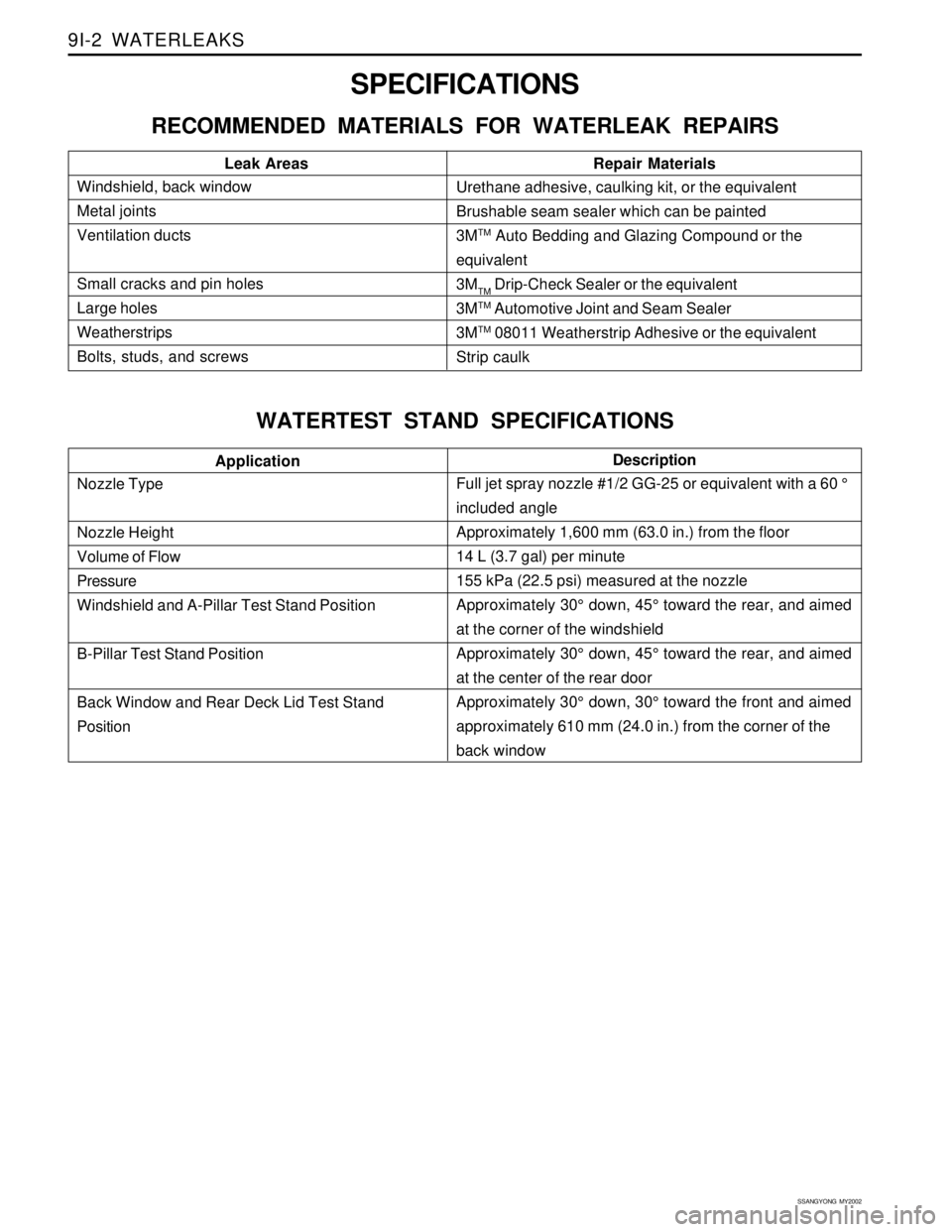
Description
SPECIFICATIONS
RECOMMENDED MATERIALS FOR WATERLEAK REPAIRS
WATERTEST STAND SPECIFICATIONS
Windshield, back window
Metal joints
Ventilation ducts
Small cracks and pin holes
Large holes
Weatherstrips
Bolts, studs, and screwsLeak Areas Repair MaterialsUrethane adhesive, caulking kit, or the equivalent
Brushable seam sealer which can be painted
3M
TM Auto Bedding and Glazing Compound or the
equivalent
3M
TM Drip-Check Sealer or the equivalent
3M
TM Automotive Joint and Seam Sealer
3M
TM 08011 Weatherstrip Adhesive or the equivalent
Strip caulk
Nozzle Type
Nozzle Height
Volume of Flow
Pressure
Windshield and A-Pillar Test Stand Position
B-Pillar Test Stand Position
Back Window and Rear Deck Lid Test Stand
PositionApplication
Full jet spray nozzle #1/2 GG-25 or equivalent with a 60 °
included angle
Approximately 1,600 mm (63.0 in.) from the floor
14 L (3.7 gal) per minute
155 kPa (22.5 psi) measured at the nozzle
Approximately 30° down, 45° toward the rear, and aimed
at the corner of the windshield
Approximately 30° down, 45° toward the rear, and aimed
at the center of the rear door
Approximately 30° down, 30° toward the front and aimed
approximately 610 mm (24.0 in.) from the corner of the
back window
Page 1811 of 2053
FRAME AND UNDERBODY 9N-9
SSANGYONG MY2002
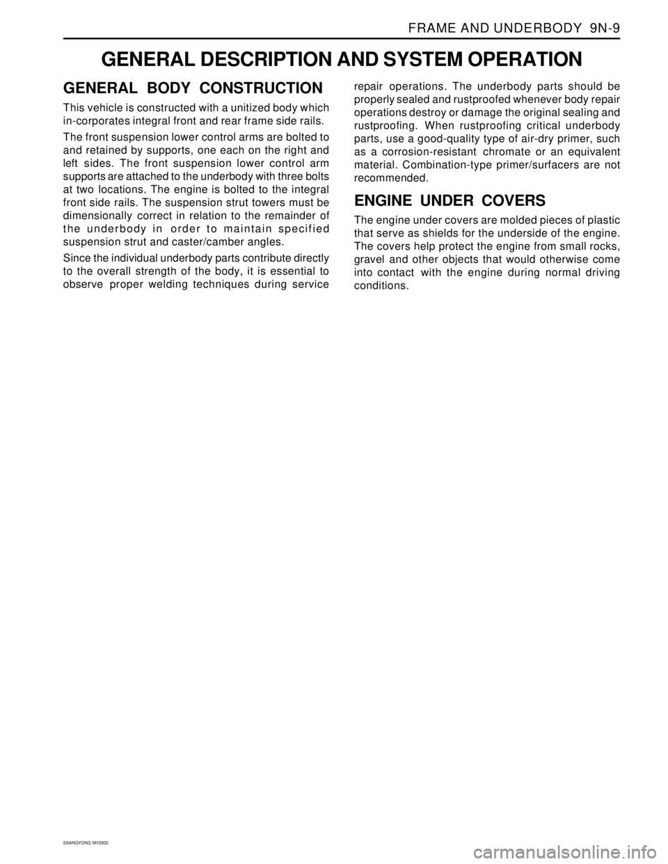
GENERAL DESCRIPTION AND SYSTEM OPERATION
GENERAL BODY CONSTRUCTION
This vehicle is constructed with a unitized body which
in-corporates integral front and rear frame side rails.
The front suspension lower control arms are bolted to
and retained by supports, one each on the right and
left sides. The front suspension lower control arm
supports are attached to the underbody with three bolts
at two locations. The engine is bolted to the integral
front side rails. The suspension strut towers must be
dimensionally correct in relation to the remainder of
the underbody in order to maintain specified
suspension strut and caster/camber angles.
Since the individual underbody parts contribute directly
to the overall strength of the body, it is essential to
observe proper welding techniques during servicerepair operations. The underbody parts should be
properly sealed and rustproofed whenever body repair
operations destroy or damage the original sealing and
rustproofing. When rustproofing critical underbody
parts, use a good-quality type of air-dry primer, such
as a corrosion-resistant chromate or an equivalent
material. Combination-type primer/surfacers are not
recommended.
ENGINE UNDER COVERS
The engine under covers are molded pieces of plastic
that serve as shields for the underside of the engine.
The covers help protect the engine from small rocks,
gravel and other objects that would otherwise come
into contact with the engine during normal driving
conditions.