1997 SSANGYONG KORANDO tow
[x] Cancel search: towPage 821 of 2053

SSANGYONG MY2002
2B-2 WHEEL ALIGNMENT
FOUR WHEEL ALIGNMENT
The first responsibility of engineering is to design safe
steering and suspension systems. Each component
must be strong enough to withstand and absorb extreme
punishment. Both the steering system and the front
and the rear suspension must function geometrically
with the body mass.
The steering and the suspension systems require that
the front wheels self-return and that the tire rolling effor t
and the road friction be held to a negligible force in
order to allow the customer to direct the vehicle with
the least effort and the most comfort.
A complete wheel alignment check should include mea-
surements of the rear toe and camber.
Four-wheel alignment assures that all four wheels will
be running in precisely the same direction.
When the vehicle is geometrically aligned, fuel economy
and tire life are at their peak, and steering and perfor
mance are maximized.
TOE-IN
Toe-in is the turning in of the tires, while toe-out is the
turning out of the tires from the geometric centerline or
thrust line. The toe ensures parallel rolling of the wheels.
The toe serves to offset the small deflections of the
wheel support system which occur when the vehicle is
rolling forward. The specified toe angle is the setting
which achieves 0 degrees of toe when the vehicle is
moving.
Incorrect toe-in or toe-out will cause tire wear and re
duced fuel economy. As the individual steering and
sus-pension components wear from vehicle mileage,
additional toe will be needed to compensate for the
wear.
Always correct the toe dimension last.
CASTER
Caster is the tilting of the uppermost point of the steering
axis either forward or backward from the vertical when
viewed from the side of the vehicle. A backward tilt is
positive, and a forward tilt is negative. Caster influences
directional control of the steering but does not affect
tire wear. Weak springs or overloading a vehicle will
affect caster. One wheel with more positive caster will
pull toward the center of the car. This condition will
cause the car to move or lean toward the side with the
least amount of positive caster. Caster is measured in
degrees.
CAMBER
Camber is the tilting of the top of the tire from the
vertical when viewed from the front of the vehicle. When
the tires tilt outward, the camber is positive. When the
tires tilt inward, the camber is negative. The camber
angle is measured in degrees from the vertical. Camber
in-fluences both directional control and tire wear.
If the vehicle has too much positive camber, the outside
shoulder of the tire will wear. If the vehicle has too
much negative camber, the inside shoulder of the tire
will wear.
DESCRIPTION AND OPERATION
Page 884 of 2053

SSAMGYONG MY2002
3A-22 FRONT AXLE
1. Heel contact
2. Toe contact
3. Face contact
4. Flank contactAdjust backlash
(Drecrease backlash)
Select proper shim(s) to
move the drive pinion
toward the ring gear
(toward toe)
Adjust backlash
(Increase backlash)
Select proper shim(s) to
move the drive pinion
against the ring gear
(toward heel)
Adjust backlash
(Increase pinion shim)
Move the drive pinion
toward the ring gear
(toward center of ring
gear)
Adjust backlash
(Decrease pinion shim)
Move the ring gear toward
the drive pinion (toward
ring gear center line) Excessive backlash (little)
Noise can be occurred
Insufficient backlash (little)
Tooth can be damaged
or broken under heavy
load
Excessive backlash (much)
Drive pinion shaft is
apart from the ring gear
Noise can be occurred
Insufficient backlash (much)
Gear contacts on the
low flank
Gear can be damaged
or worn
Noise can be occurred
Inspection of Ring Gear Tooth Contact
Pattern
Normal Contact
Apply gear-marking compound (Prussian blue / red
lead) on the ring gear teeth. Rotate the ring gear and
check the tooth contact pattern.
KAA3A450
Abnormal Contact
Tooth contact pattern Possible cause Remedy
KAA3A460
KAA3A470
KAA3A480KAA3A500
KAA3A510
KAA3A520
KAA3A490KAA3A530
Page 916 of 2053

SSANGYONG MY2002
3D-22 REAR AXLE
Adjust backlash
(Drecrease backlash)
Select proper shin to
move the drive pinion
toward the ring gear
(toward toe)
Adjust backlash
(Increase backlash)
Select proper shim to
move the drive pinion
against the ring gear
(toward heel)
Adjust backlash
(Increase pinion shim)
Move the drive pinion
toward the ring gear
(toward center of ring
gear)
Adjust backlash
(Decrease pinion shim)
Move the ring gear
toward the drive pinion
(toward ring gear
center line) Excessive backlash
Noise can be occurred
Insufficient backlash
Tooth can be damaged
or broken under heavy
load
Excessive backlash
Drive pinion shaft is
apart from the ring gear
Noise can be occurred
Insufficient backlash
Gear contacts on the
low flank
Gear can be damaged
or worn
Noise can be occurred
Inspection of Ring Gear Tooth Contact
Pattern
1. Normal Contact
Apply gear-marking compound (prussian blue/red
lead) on the ring rear teeth. Rotate the ring gear
and check the to the contact pattern.
KAA3D500
Tooth contact pattern Possible cause Remedy
KAA3D510
KAA3D530
KAA3D550KAA3D520
KAA3D540
KAA3D560
KAA3D570KAA3D580
2. Abnormal contact
1. Heel contact
2. Toe contact
3. Face contact
4. Flank contact
Page 962 of 2053

SSANGYONG MY2002
4E-2 REAR BRAKES
DESCRIPTION AND OPERATION
DRUM BRAKE
This drum brake assembly is a leading/trailing shoe
design.
Both brake shoes are held against the wheel cylinder
pistons by the lower return spring and the fixed anchor
plate near the lower return spring. When the brakes
are applied, the wheel cylinder pistons move both
shoes out to contact the drum. With forward wheel
rotation, the forward brake shoe will wrap into the drum
and become selt-energized. With reverse wheel
rotation, brake shoes is transferred to the anchor plate
through the braking plate to the axle flange.
Adjustment is automatic and occurs on any service
brake application. Do not switch the position of shoes
that have been in service, as this may render the self-
adjustment feature inoperative and result in increased
pedal travel.
The brake drum must have high abrasion resistance,
heatproof, high stiffness, fatigue stiffness and strength
enough not to make any deformation. The temperature
of the drum surface comes up to 500 - 700 °C on brake
operation by the friction with the lining. When the
temperature of the drum surface continues to keep
high, the friction coefficient goes down and the ‘fade
development’ occurs. When the brake is applied often
on the hill, any accident may be occur.
YAD4C010
Wheel Cylinder
Both wheel cylinder diameters are same in order to
balance the friction forces of both shoes.
The hydraulic pressure from the master cylinder is
provided to the wheel cylinder and the piston in the
wheel cylinder allows to push both shoes toward the
drum resulted in generating the braking force.
Brake Lining
The brake lining is installed with the brake shoe and
pushed toward the drum for applying the brake pedal.
Thus, lining must have high-heat tolerance, abrasion
resistance and high friction coefficient.
Brake Lining and Drum Clearance Automatic
Control System
If the lining’s wear is excessive, the piston moves to
long distance and the pedal travel increases. The
clearance between the drum and the brake lining
should be adjusted.
Generally the drum brake must be adjusted regularly
and thus the clearance automatic control system
enables to adjust the clearance between the brake
lining and the drum resulting from brake lining wear.
YAD4C020
1 Cylinder Housing
2 Boot
3 Spring
4 Piston Cup
5 Piston
6 Air Bleeder1 Cylinder Housing
2 Boot
3 Spring
4 Piston Cup
5 Piston
6 Air Bleeder
Page 1085 of 2053

SSANGYONG MY2002
4F-102 ABS AND TCS
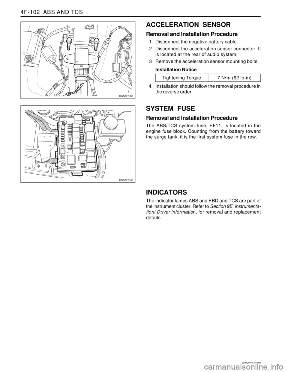
ACCELERATION SENSOR
Removal and Installation Procedure
1. Disconnect the negative battery cable.
2. Disconnect the acceleration sensor connector. It
is located at the rear of audio system.
3. Remove the acceleration sensor mounting bolts.
Installation Notice
SYSTEM FUSE
Removal and Installation Procedure
The ABS/TCS system fuse, EF11, is located in the
engine fuse block. Counting from the battery toward
the surge tank, it is the first system fuse in the row.
KAA4F410
KAA4F420
Tightening Torque 7 Nm (62 lb-in)
4. Installation should follow the removal procedure in
the reverse order.
INDICATORS
The indicator lamps ABS and EBD and TCS are part of
the instrument cluster. Refer to Section 9E, instrumenta-
tion/ Driver information, for removal and replacement
details.
Page 1133 of 2053

AUTOMATIC TRANSMISSION 5A-39
SSANGYONG MY2002
4. Place a fluid container below the fluid filler plug.
5. Clean all dirt from around the fluid filler plug.
Remove the fluid filler plug. Clean the filler plug
and check that there is no damage to the ‘O’ ring.
If fluid drains through the filler hole the transmis-
sion may have been overfilled. When the fluid
stops draining the fluid level is correct. Install
the fluid filler plug and tighten it to 33 Nm (24
lb-ft).
If fluid does not drain through the filler hole, the
transmission fluid level may be low. Install the
filler pump into the filler hole. Lower the vehicle
with the filler pump still connected and partially
fill the fluid through the filler hole.
Start the vehicle in P (Park) with the parking
brake and the brake applied. With the engine
idling, move the gear shift. control lever through
the gear ranges, pausing a few seconds in each
range and adding the fluid until gear application
is felt.
Return the gear shift lever to P (Park).
Turn the engine OFF and raise the vehicle. When
the three minutes passed after the engine
stopped, remove the filler pump.
Check if the fluid level is aligned with the bottom
of the filler hole. If not, add a small quantity of
fluid to the correct level. Install the fluid filler
plug and tighten it to 33 Nm (24 lb-ft).
If fluid does not drain through the filler hole al-
though adding a total of 1.5 liters, the transmission
should be inspected for fluid leaks and any leaks
should be fixed before setting the transmission
fluid level.
6. When the fluid level checking procedure is com-
pleted, wipe any fluid around the filler plug with a
rag or shop towel.
Fluid Level Set After Service
1. Depending on the service procedure performed,
add the following amounts of fluid through the filler
plug hole prior to adjusting the fluid level:
Converter empty 8.0 liters (8.5 quarts)
Converter full 3.8 liters (4.0 quarts)
2. Follow steps 1 through 4 of the Fluid Level Diagnosis
Procedure.
3. Clean all dirt from around the fluid filler plug.
Remove the fluid filler plug. Clean the filler plug
and check that there is no damage to the ‘O’ ring.
4. Lower the vehicle with the filler pump still connected
and start the vehicle in P (Park) with the parking
brake and the brake applied. With the engine idling,
move the gear shift control lever through the gear
ranges, pausing a few seconds in each range and
adding the fluid until gear application is felt.Then add an additional 0.5 litres of fluid. Return
the gear shift lever to P (Park). Turn the engine OFF
and raise the vehicle. Install the fluid filler plug and
tighten it to 33 Nm (24 lb-ft).
5. Drive the vehicle at 3.5 to 4.5 kilometers with light
throttle so that the engine does not exceed 2500
rpm.
This should result in the transmission temperature
being in the range 50 - 60 °C (82 - 140 °F). With the
brake applied, move the shift lever through the gear
ranges, pausing a few seconds in each range at
the engine idling.
6. Return the gear shift lever to P (Park).
Turn the en-gine OFF and raise the vehicle on the
hoist, if applicable, ensuring the vehicle is level.
When the three minutes passed after the engine
stopped, remove the filler plug.
Check if the fluid level is aligned with the bottom of
the filler hole. If not, add a small quantity of fluid to
the correct level. Install the fluid filler plug and
tighten it to 33 Nm (24 lb-ft).
7. Wipe any fluid around the filler plug with a rag or
shop towel.
FLUID LEAK DIAGNOSIS AND
REPAIR
The cause of most external leaks can generally be lo-
cated and repaired with the transmission in the vehicle.
Methods for Locating Leaks
General Method
1. Verify that the leak is transmission fluid.
2. Thoroughly clean the suspected leak area.
3. Drive the vehicle for approximately 25 km (15 miles)
or until the transmission reaches normal operating
temperature (88 °C, 190 °F).
4. Park the vehicle over clean paper or cardboard.
5. Turn the engine OFF and look for fluid spots on the
paper.
6. Make the necessary repairs to correct the leak.
Powder Method
1. Thoroughly clean the suspected leak area.
2. Apply an aerosol type powder (foot powder) to the
suspected leak area.
3. Drive the vehicle for approximately 25 km (15 miles)
or until the transmission reaches normal operating
temperature (88 °C, 190 °F).
4. Turn the engine OFF.
5. Inspect the suspected leak area and trace the leak
path through the powder to find the source of the
leak.
6. Make the necessary repairs.
Page 1317 of 2053

MANUAL TRANSMISSION 5B-9
SSANGYONG MY2002
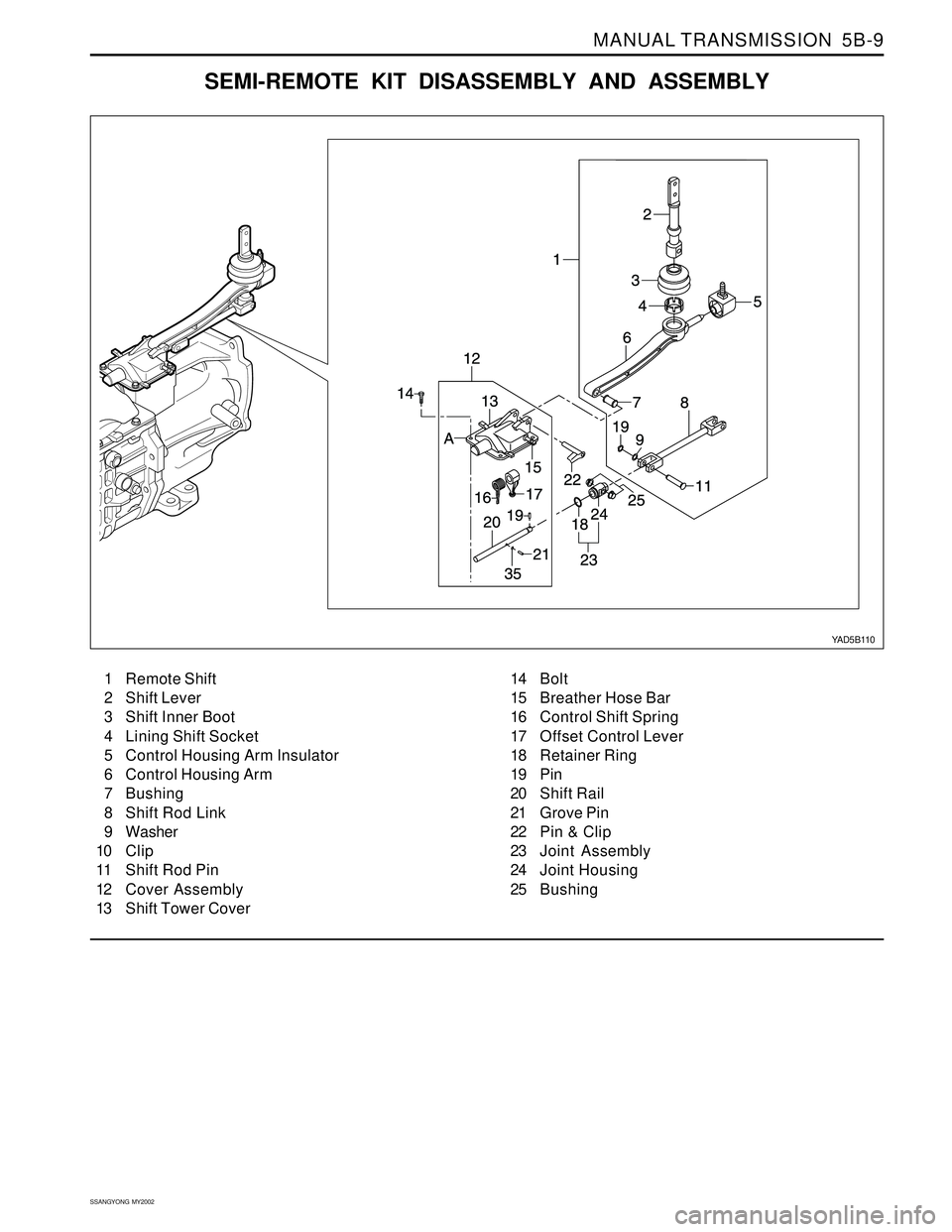
SEMI-REMOTE KIT DISASSEMBLY AND ASSEMBLY
YAD5B110
1 Remote Shift
2 Shift Lever
3 Shift Inner Boot
4 Lining Shift Socket
5 Control Housing Arm Insulator
6 Control Housing Arm
7 Bushing
8 Shift Rod Link
9 Washer
10 Clip
11 Shift Rod Pin
12 Cover Assembly
13 Shift Tower Cover14 Bolt
15 Breather Hose Bar
16 Control Shift Spring
17 Offset Control Lever
18 Retainer Ring
19 Pin
20 Shift Rail
21 Grove Pin
22 Pin & Clip
23 Joint Assembly
24 Joint Housing
25 Bushing
Page 1320 of 2053

SSANGYONG MY2002
5B-12 MANUAL TRANSMISSION
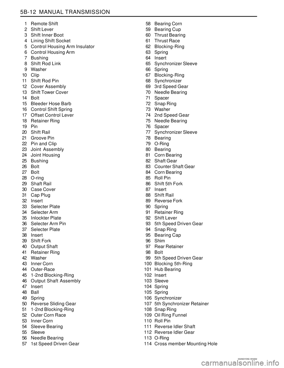
1 Remote Shift
2 Shift Lever
3 Shift Inner Boot
4 Lining Shift Socket
5 Control Housing Arm Insulator
6 Control Housing Arm
7 Bushing
8 Shift Rod Link
9 Washer
10 Clip
11 Shift Rod Pin
12 Cover Assembly
13 Shift Tower Cover
14 Bolt
15 Bleeder Hose Barb
16 Control Shift Spring
17 Offset Control Lever
18 Retainer Ring
19 Pin
20 Shift Rail
21 Groove Pin
22 Pin and Clip
23 Joint Assembly
24 Joint Housing
25 Bushing
26 Bolt
27 Bolt
28 O-ring
29 Shaft Rail
30 Case Cover
31 Cap Plug
32 Insert
33 Selecter Plate
34 Selecter Arm
35 Inlockter Plate
36 Selecter Arm Pin
37 Selecter Plate
38 Insert
39 Shift Fork
40 Output Shaft
41 Retainer Ring
42 Washer
43 Inner Corn
44 Outer-Race
45 1-2nd Blocking-Ring
46 Output Shaft Assembly
47 Insert
48 Ball
49 Spring
50 Reverse Sliding Gear
51 1-2nd Blocking-Ring
52 Outer Corn Race
53 Inner Corn
54 Sleeve Bearing
55 Sleeve
56 Needle Bearing
57 1st Speed Driven Gear58 Bearing Corn
59 Bearing Cup
60 Thrust Bearing
61 Thrust Race
62 Blocking-Ring
63 Spring
64 Insert
65 Synchronizer Sleeve
66 Spring
67 Blocking-Ring
68 Synchronizer
69 3rd Speed Gear
70 Needle Bearing
71 Spacer
72 Snap Ring
73 Washer
74 2nd Speed Gear
75 Needle Bearing
76 Spacer
77 Synchronizer Sleeve
78 Bearing
79 O-Ring
80 Bearing
81 Corn Bearing
82 Shaft Gear
83 Counter Shaft Gear
84 Corn Bearing
85 Roll Pin
86 Shift 5th Fork
87 Insert
88 Shift Rail
89 Reverse Fork
90 Spring
91 Retainer Ring
92 Shift Lever
93 5th Speed Driven Gear
94 Snap Ring
95 Bearing Cap
96 Shim
97 Rear Retainer
98 Bolt
99 5th Speed Driven Gear
100 Blocking 5th-Ring
101 Hub Bearing
102 Insert
103 Sleeve
104 Spring
105 Spring
106 Synchronizer
107 5th Synchronizer Retainer
108 Snap Ring
109 Oil Ring Funnel
110 Roll Pin
111 Reverse Idler Shaft
112 Reverse Idler Gear
113 O-Ring
114 Cross member Mounting Hole