1997 SSANGYONG KORANDO tow
[x] Cancel search: towPage 1333 of 2053
MANUAL TRANSMISSION 5B-25
SSANGYONG MY2002
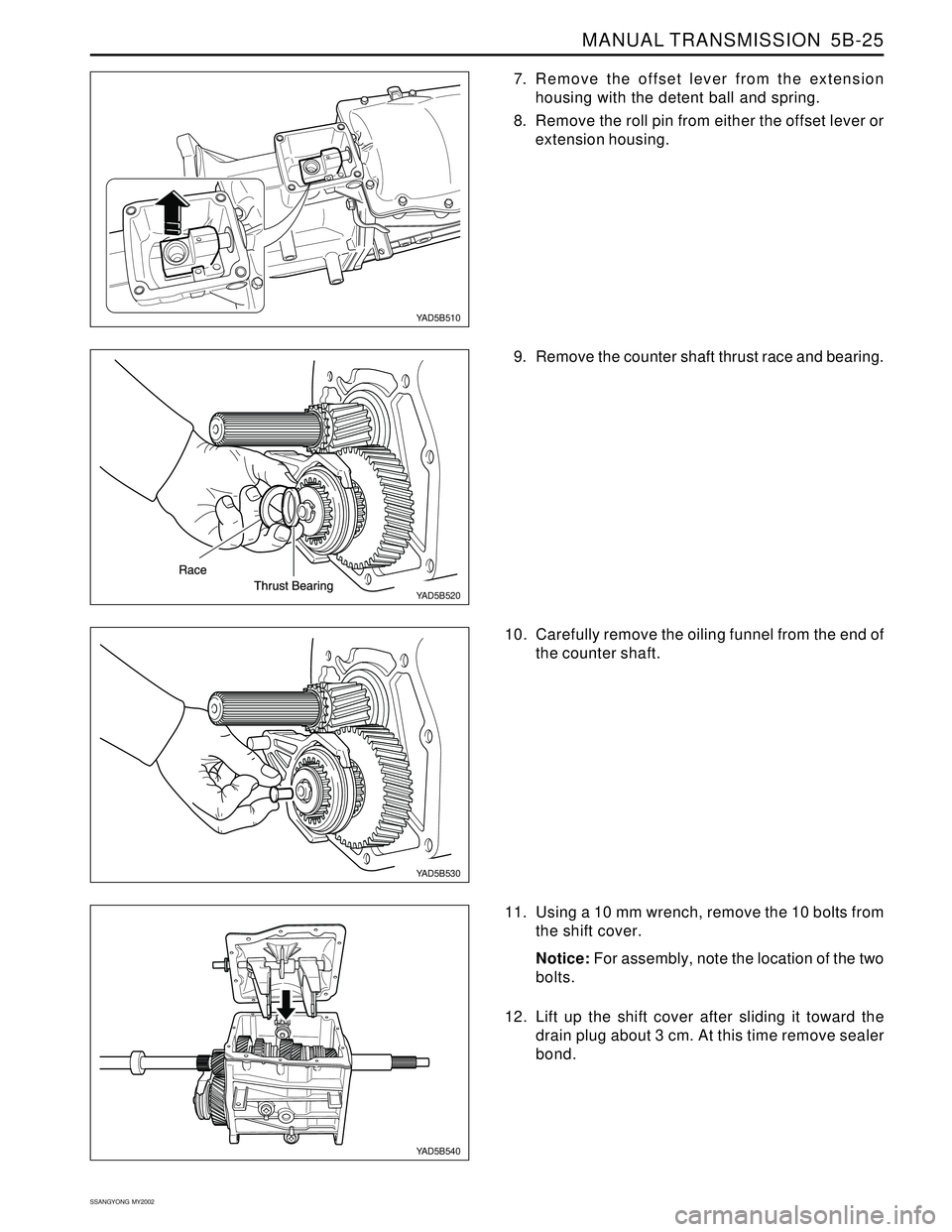
7. Remove the offset lever from the extension
housing with the detent ball and spring.
8. Remove the roll pin from either the offset lever or
extension housing.
YAD5B510
YAD5B520
YAD5B540
YAD5B530
9. Remove the counter shaft thrust race and bearing.
10. Carefully remove the oiling funnel from the end of
the counter shaft.
11. Using a 10 mm wrench, remove the 10 bolts from
the shift cover.
Notice: For assembly, note the location of the two
bolts.
12. Lift up the shift cover after sliding it toward the
drain plug about 3 cm. At this time remove sealer
bond.
Page 1381 of 2053
TRANSFER CASE 5D1-11
SSANGYONG MY2002
DIAGNOSIS
While the transfer case control unit (TCCU) is active it
periodically monitors its inputs and outputs. If a fault
is detected the 4WD CHECK lamp is illuminated and a
fault code is stored in the TCCU memory.
When requested, fault codes are downloaded to scan
tool through a diagnostic connector (K-line) serial com
munication.
SELF-DIAGNOSTIC TESTS
TCCU Internal Function
When the ignition is turned on the TCCU tests its read
only memory (ROM) and random access memory
(RAM). If there is a fault, the TCCU immediately resets
itself and re-tests the ROM and RAM. If the fault
persists the TCCU continues to reset and re-test until
the fault is corrected or the ignition is turned off. All
TCCU functions are inhibited until the fault is corrected.
The 4WD CHECK lamp is not illuminated if there is a
ROM or RAM fault.
If the ROM/RAM passes the electronically erasable
programmable read only memory (EEPROM) is tested.
If there is a fault the 4WD CHECK lamp is illuminated
and the TCCU continues to operate using the default
calibration data stored in ROM. Fault codes are not
stored when there is an EEPROM fault.
An EEPROM fault can only be cleared by cycling
ignition OFF-ON.
Shift Motor Assembly Test
If the TCCU detects a shift motor or position encoder
fault continuously for one second the 4WD CHECK
lamp is turned on and the appropriate fault code is
stored in memory.
1. A shift motor fault when the motor is off is defined
as follows:
Motor HI-LO circuits are shorted to ground.
Motor LO-HI circuits are shorted to ground.
Motor circuits are open.
2. A shift motor fault when the motor is energized is
defined as follows:
Motor HI-LO circuits are shorted to ground.
Motor LO-HI circuits are shorted to ground.
Motor HI-LO circuits are shorted to motor LO
HI circuits.
Motor circuits are open.
3. A position encoder fault is defined as follows:
Any position code which does not correspond
to the valid 9 codes.
A short to ground on any of the encoder lines.
4. If no shifts are in progress when a failure occurs
the TCCU will not respond to any shift commands.5. If a shift command has been received but not
acted upon when a failure occurred the TCCU
would cancel the command and not respond to
any subsequent shift commands.
6. If a shift command is in progress when an invalid
position code is confirmed it will be halted and
the TCCU will turn the motor toward the high
position. Afterwards the TCCU will not respond to
any shift commands.
7. If the shift motor or position encoder assembly
failures, other than a motor failure which occurs
when the motor is energized, recovers continuously
for one second the TCCU will function normally.
The 4WD CHECK lamp is turned off but the fault
code will remain in memory.
8. A motor failure (i.e. open or short circuit) which
occurs when the motor is energized can only be
cleared by cycling the ignition OFF-ON.
Front Speed Sensor Test
If a front speed sensor fault is detected continuously
for 0.5 second the 4WD CHECK lamp is illuminated.
The TCCU then responds as follows:
1. If the system is in high range the TCCU uses the
rear speed sensor to determine the EMC touch off
level and wheel slip control is suspended.
2. If the system is in low range, the EMC duty cycle
is set to maximum, independent of vehicle speed,
until the system is shifted out of low range.
3. All electric shift activity is halted until the Ignition
is cycled. If a shift is in progress it will be
completed.
If the front speed sensor recovers continuously for O.5
second the TCCU will function normally. The 4WD
CHECK lamp is turned off but the fault code will remain
in memory.
Rear Speed Sensor Test
If a rear speed sensor fault is detected continuously
for 0.5 second the 4WD CHECK lamp is illuminated.
The TCCU then responds as follows:
1. If the system is in high range the TCCU uses the
front speed sensor to determine the EMC touch
off level and wheel slip control is suspended.
2. If the system is in low range, the EMC duty cycle
is set to maximum independent of vehicle speed
until the system is shifted out of low range.
3. All electric shift activity is halted until the Ignition
is cycled. If a shift is in progress it will be
completed.
4. If the rear speed sensor recovers continuously for
0.5 second the TCCU will function normally. The
4WD CHECK lamp is turned off but the fault code
will remain in memory.
Page 1397 of 2053
TRANSFER CASE 5D1-75
SSANGYONG MY2002
KAA5D510
KAA5D520
KAA5D460
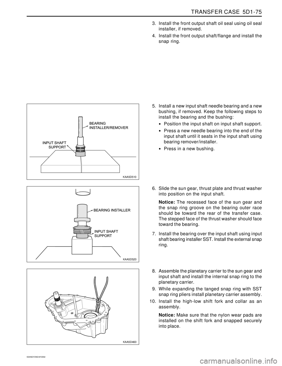
3. Install the front output shaft oil seal using oil seal
installer, if removed.
4. Install the front output shaft/flange and install the
snap ring.
8. Assemble the planetary carrier to the sun gear and
input shaft and install the internal snap ring to the
planetary carrier.
9. While expanding the tanged snap ring with SST
snap ring pliers install planetary carrier assembly.
10. Install the high-low shift fork and collar as an
assembly.
Notice: Make sure that the nylon wear pads are
installed on the shift fork and snapped securely
into place. 6. Slide the sun gear, thrust plate and thrust washer
into position on the input shaft.
Notice: The recessed face of the sun gear and
the snap ring groove on the bearing outer race
should be toward the rear of the transfer case.
The stepped face of the thrust washer should face
toward the bearing.
7. Install the bearing over the input shaft using input
shaft bearing installer SST. Install the external snap
ring. 5. Install a new input shaft needle bearing and a new
bushing, if removed. Keep the following steps to
install the bearing and the bushing:
Position the input shaft on input shaft support.
Press a new needle bearing into the end of the
input shaft until it seats in the input shaft using
bearing remover/installer.
Press in a new bushing.
Page 1398 of 2053
SSANGYONG MY2002
5D1-76 TRANSFER CASE
KAA5D440
KAA5D430
KAA5D420
KAA5D410
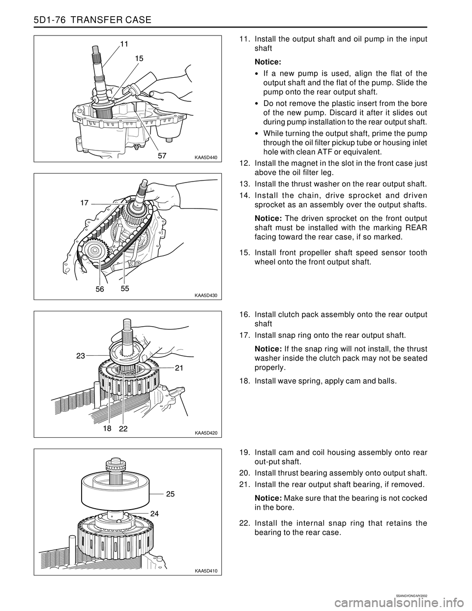
11. Install the output shaft and oil pump in the input
shaft
Notice:
If a new pump is used, align the flat of the
output shaft and the flat of the pump. Slide the
pump onto the rear output shaft.
Do not remove the plastic insert from the bore
of the new pump. Discard it after it slides out
during pump installation to the rear output shaft.
While turning the output shaft, prime the pump
through the oil filter pickup tube or housing inlet
hole with clean ATF or equivalent.
12. Install the magnet in the slot in the front case just
above the oil filter leg.
13. Install the thrust washer on the rear output shaft.
14. Install the chain, drive sprocket and driven
sprocket as an assembly over the output shafts.
Notice: The driven sprocket on the front output
shaft must be installed with the marking REAR
facing toward the rear case, if so marked.
15. Install front propeller shaft speed sensor tooth
wheel onto the front output shaft.
19. Install cam and coil housing assembly onto rear
out-put shaft.
20. Install thrust bearing assembly onto output shaft.
21. Install the rear output shaft bearing, if removed.
Notice: Make sure that the bearing is not cocked
in the bore.
22. Install the internal snap ring that retains the
bearing to the rear case. 16. Install clutch pack assembly onto the rear output
shaft
17. Install snap ring onto the rear output shaft.
Notice: If the snap ring will not install, the thrust
washer inside the clutch pack may not be seated
properly.
18. Install wave spring, apply cam and balls.
Page 1399 of 2053
TRANSFER CASE 5D1-77
SSANGYONG MY2002
KAA5D420
KAA5D590
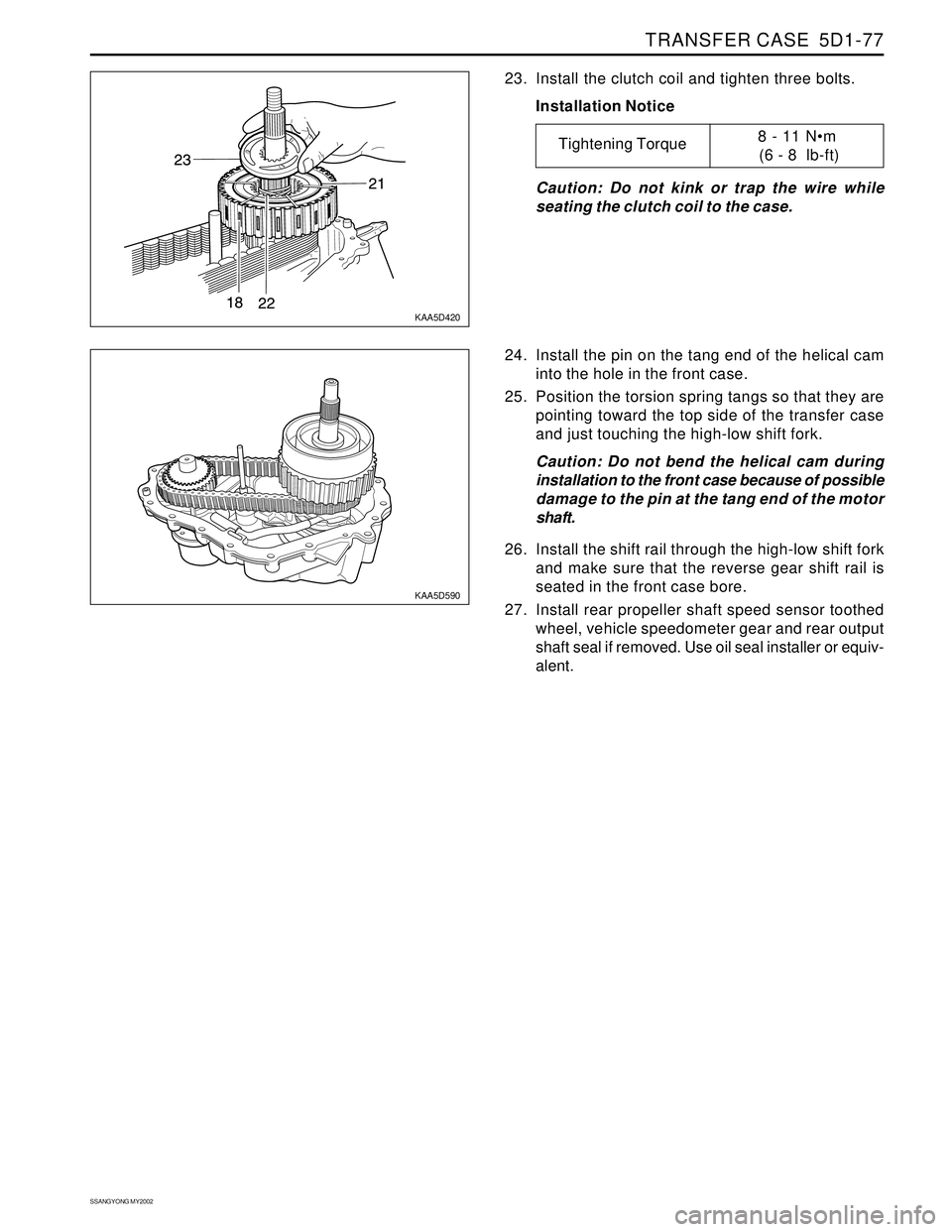
23. Install the clutch coil and tighten three bolts.
Installation Notice
Caution: Do not kink or trap the wire while
seating the clutch coil to the case.
24. Install the pin on the tang end of the helical cam
into the hole in the front case.
25. Position the torsion spring tangs so that they are
pointing toward the top side of the transfer case
and just touching the high-low shift fork.
Caution: Do not bend the helical cam during
installation to the front case because of possible
damage to the pin at the tang end of the motor
shaft.
26. Install the shift rail through the high-low shift fork
and make sure that the reverse gear shift rail is
seated in the front case bore.
27. Install rear propeller shaft speed sensor toothed
wheel, vehicle speedometer gear and rear output
shaft seal if removed. Use oil seal installer or equiv-
alent.
Tightening Torque8 - 11 Nm
(6 - 8 lb-ft)
Page 1402 of 2053
SSANGYONG MY2002
5D2-2 TRANSFER CASE (PART TIME - 4408)
2WD Drive (Rear
Wheel Drive)
4WD Drive (High
Speed)
4WD Drive (Low
Speed)
2WD Drive
↔ 4WD
Drive (High Speed)
2WD Drive, 4WD
Drive (High Speed)
↔ 4WD Drive (Low
Speed)
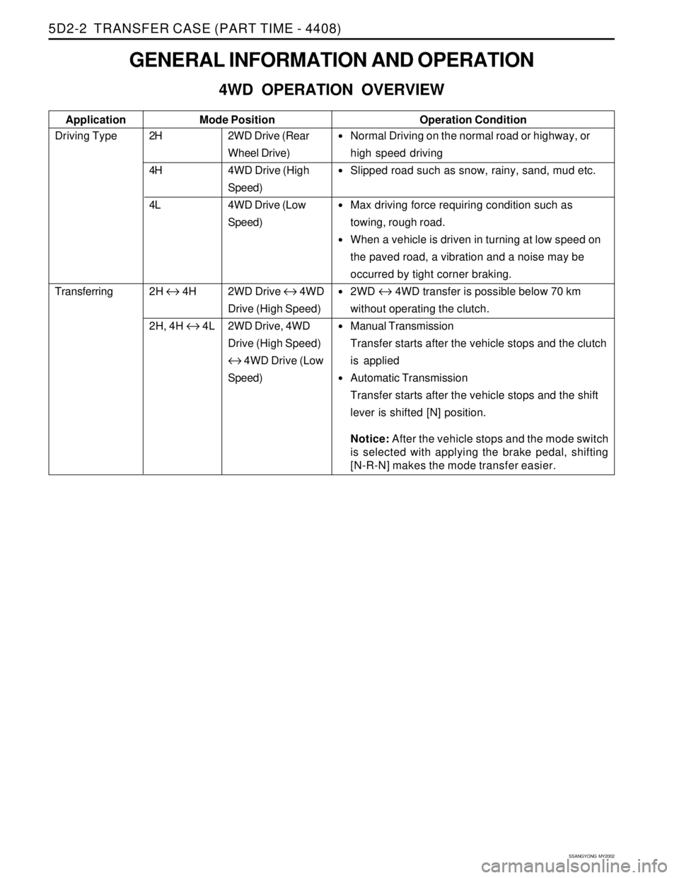
GENERAL INFORMATION AND OPERATION
4WD OPERATION OVERVIEW
Driving Type
Transferring2H
4H
4L
2H
↔ 4H
2H, 4H
↔ 4L Application
•Normal Driving on the normal road or highway, or
high speed driving
Slipped road such as snow, rainy, sand, mud etc.
Max driving force requiring condition such as
towing, rough road.
When a vehicle is driven in turning at low speed on
the paved road, a vibration and a noise may be
occurred by tight corner braking.
2WD ↔ 4WD transfer is possible below 70 km
without operating the clutch.
Manual Transmission
Transfer starts after the vehicle stops and the clutch
is applied
Automatic Transmission
Transfer starts after the vehicle stops and the shift
lever is shifted [N] position.
Notice: After the vehicle stops and the mode switch
is selected with applying the brake pedal, shifting
[N-R-N] makes the mode transfer easier.
Operation ConditionMode Position
Page 1543 of 2053
SSANGYONG MY2002
7C-14 MANUAL & SEMIAUTO-HVAC
REFRIGERANT CHARGING
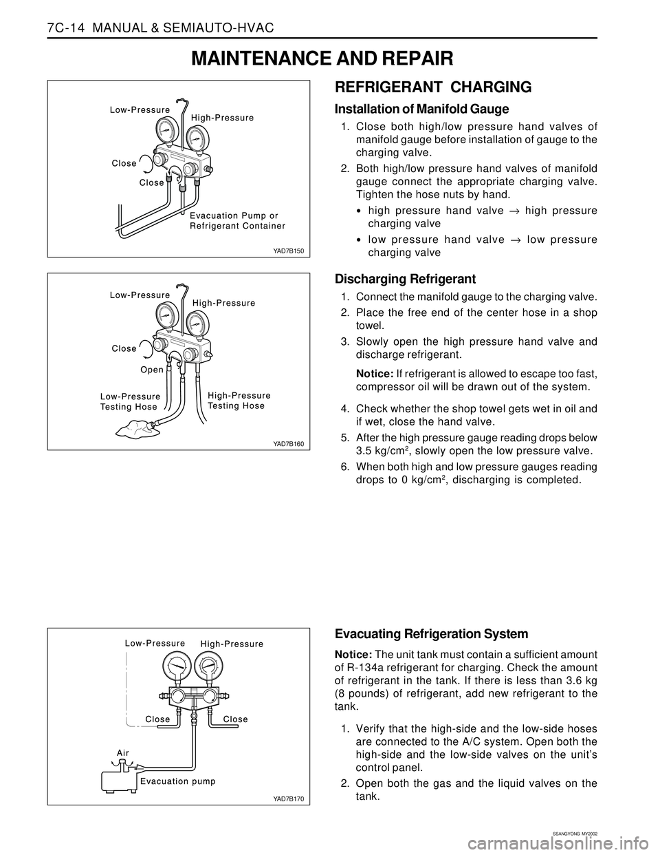
Installation of Manifold Gauge
1. Close both high/low pressure hand valves of
manifold gauge before installation of gauge to the
charging valve.
2. Both high/low pressure hand valves of manifold
gauge connect the appropriate charging valve.
Tighten the hose nuts by hand.
high pressure hand valve → high pressure
charging valve
low pressure hand valve → low pressure
charging valve
Discharging Refrigerant
1. Connect the manifold gauge to the charging valve.
2. Place the free end of the center hose in a shop
towel.
3. Slowly open the high pressure hand valve and
discharge refrigerant.
Notice: If refrigerant is allowed to escape too fast,
compressor oil will be drawn out of the system.
4. Check whether the shop towel gets wet in oil and
if wet, close the hand valve.
5. After the high pressure gauge reading drops below
3.5 kg/cm
2, slowly open the low pressure valve.
6. When both high and low pressure gauges reading
drops to 0 kg/cm
2, discharging is completed.
Evacuating Refrigeration System
Notice: The unit tank must contain a sufficient amount
of R-134a refrigerant for charging. Check the amount
of refrigerant in the tank. If there is less than 3.6 kg
(8 pounds) of refrigerant, add new refrigerant to the
tank.
1. Verify that the high-side and the low-side hoses
are connected to the A/C system. Open both the
high-side and the low-side valves on the unit’s
control panel.
2. Open both the gas and the liquid valves on the
tank.
YAD7B150
YAD7B160
YAD7B170
MAINTENANCE AND REPAIR
Page 1546 of 2053
MANUAL & SEMIAUTO-HVAC 7C-17
SSANGYONG MY2002
����� �����
�����
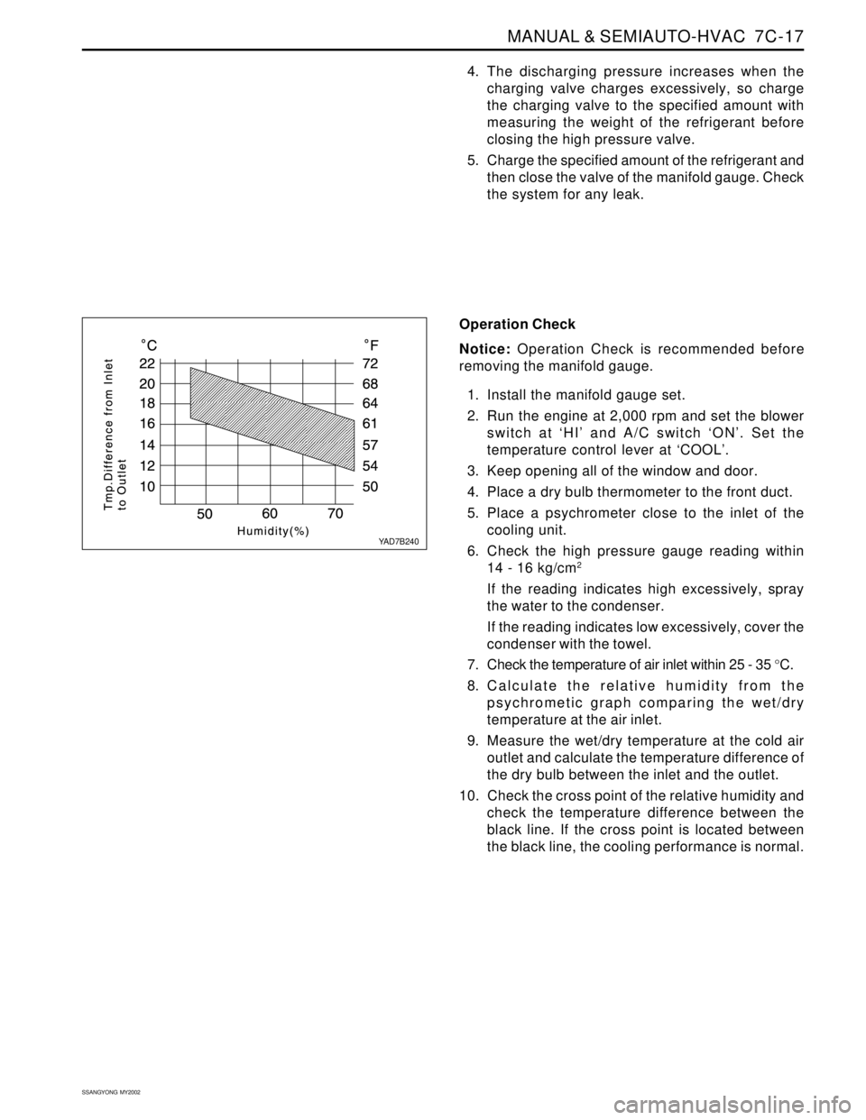
Operation Check
Notice: Operation Check is recommended before
removing the manifold gauge.
1. Install the manifold gauge set.
2. Run the engine at 2,000 rpm and set the blower
switch at ‘HI’ and A/C switch ‘ON’. Set the
temperature control lever at ‘COOL’.
3. Keep opening all of the window and door.
4. Place a dry bulb thermometer to the front duct.
5. Place a psychrometer close to the inlet of the
cooling unit.
6. Check the high pressure gauge reading within
14 - 16 kg/cm
2
If the reading indicates high excessively, spray
the water to the condenser.
If the reading indicates low excessively, cover the
condenser with the towel.
7. Check the temperature of air inlet within 25 - 35 °C.
8. Calculate the relative humidity from the
psychrometic graph comparing the wet/dry
temperature at the air inlet.
9. Measure the wet/dry temperature at the cold air
outlet and calculate the temperature difference of
the dry bulb between the inlet and the outlet.
10. Check the cross point of the relative humidity and
check the temperature difference between the
black line. If the cross point is located between
the black line, the cooling performance is normal.
4. The discharging pressure increases when the
charging valve charges excessively, so charge
the charging valve to the specified amount with
measuring the weight of the refrigerant before
closing the high pressure valve.
5. Charge the specified amount of the refrigerant and
then close the valve of the manifold gauge. Check
the system for any leak.
YAD7B240