Page 1456 of 2053

POWER STEERING SYSTEM 6A-5
SSANGYONG MY2002
BLEEDING THE POWER
STEERING SYSTEM
1. Disconnect the fuel line. Using a starter motor,
crank the engine and turn the steering wheel from
lock to start 5 or 6 times.
Notice: Do bleeding with engine cranking. If bleed
with idling, there can be a air contact with oil.
2. Connect the fuel feed line and start the engine at
idle speed.
3. Turn the steering wheel from lock to lock until there
is no more air in oil reservoir.
4. Connect the oil level is within specification.
5. By turning the steering wheel left to right, check
the oil level change.
Notice: If oil is not changes more than 5 mm, do
bleeding again. If oil level rises suddenly when
stopped engine, again.
MAINTENANCE
CHECKING AND ADDING FLUID
Notice: When adding fluid or making a complete fluid
change, always use DEXRON. - II power steering fluid.
Failure to use the proper fluid will cause hose and seal
damage and fluid leaks.
1. The power steering fluid level is indicated by marks
on a fluid level indicator on the fluid reservoir cap.
2. If the fluid is warmed up to 66 °C (150 °F), the fluid
level should be between the MAX and MIN marks.
Add fluid as needed.
3. If the fluid is cool, 21 °C (70 °F), the fluid level should
be at the MIN mark. Add fluid as needed.
Page 1530 of 2053

SECTION 7C
MANUAL CONTROL / SEMIAUTO
TEMPERATURE CONTROL HEATING,
VENTILATION AND AIR CONDITIONING
SYSTEM
CAUTION: Disconnect the negative battery cable before removing or installing any electrical unit or when
a tool or equipment could easily come in contact with exposed electrical terminals. Disconnecting this
cable will help prevent personal injury and damage to the vehicle. The ignition must also be in LOCK
unless other-wise noted.
TABLE OF CONTENTS
Specifications.......................................................7C-2
Refrigerant..........................................................7C-2
Evaporator Unit....................................................7C-2
Blower Unit..........................................................7C-2
Compressor.........................................................7C-2
Condenser...........................................................7C-2
Receiver Drier......................................................7C-2
Pressure Switch...................................................7C-3
Air Filter...............................................................7C-3
Heater Unit..........................................................7C-3
Fastener Tightening Specifications.......................7C-3
Diagnosis..............................................................7C-4
Defectives in Fan Motor Circuit.............................7C-5
Defectives in Compressor Circuit.........................7C-6
Diagnosis Using the Manifold Gauge...................7C-7Component Locator.............................................7C-9
Ventilation............................................................7C-9
Heater System ................................................... 7C-11
Air Conditioner System...................................... 7C-12
Diesel Engine .................................................... 7C-12
Gasoline Engine................................................ 7C-13
Maintenance and Repair................................... 7C-14
Refrigerant Charging .......................................... 7C-14
Compressor Oil Replacement............................ 7C-18
Repair Instructions.............................................. 7C-19
On-Vehicle Service............................................... 7C-19
Condener.......................................................... 7C-19
Receiver Drier.................................................... 7C-21
Air - Conditioner Compressor............................. 7C-23
Heater and Air Conditioner Control Box.............. 7C-24
Air Filter............................................................. 7C-25
Page 1536 of 2053

MANUAL & SEMIAUTO-HVAC 7C-7
SSANGYONG MY2002
DIAGNOSIS USING THE MANIFOLD GAUGE
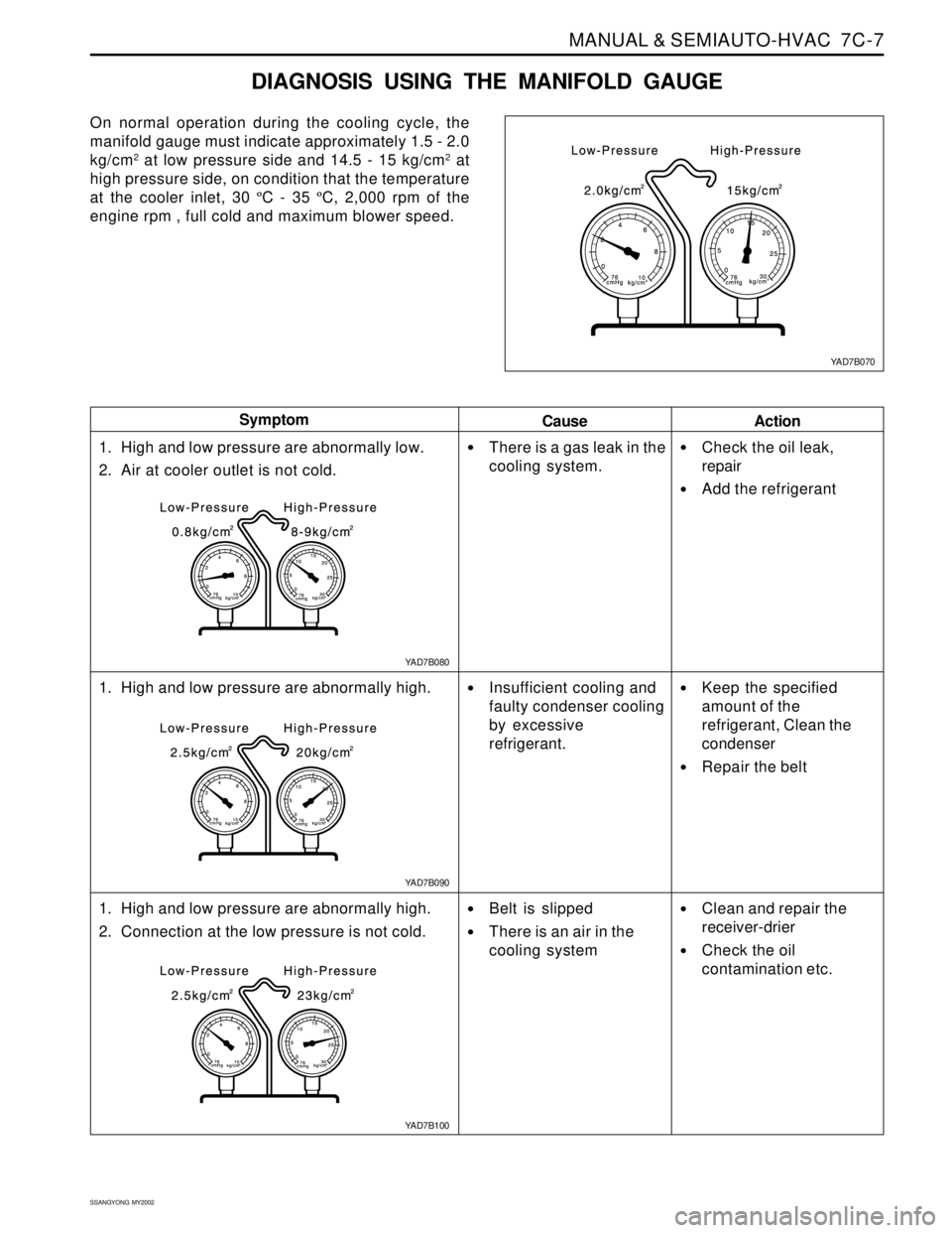
On normal operation during the cooling cycle, the
manifold gauge must indicate approximately 1.5 - 2.0
kg/cm
2 at low pressure side and 14.5 - 15 kg/cm2 at
high pressure side, on condition that the temperature
at the cooler inlet, 30 ºC - 35 ºC, 2,000 rpm of the
engine rpm , full cold and maximum blower speed.
Cause Symptom
Action
1. High and low pressure are abnormally low.
2. Air at cooler outlet is not cold.
1. High and low pressure are abnormally high.
1. High and low pressure are abnormally high.
2. Connection at the low pressure is not cold.
There is a gas leak in the
cooling system.
Insufficient cooling and
faulty condenser cooling
by excessive
refrigerant.
Belt is slipped
There is an air in the
cooling system
Check the oil leak,
repair
Add the refrigerant
Keep the specified
amount of the
refrigerant, Clean the
condenser
Repair the belt
Clean and repair the
receiver-drier
Check the oil
contamination etc.
YAD7B070
YAD7B080
YAD7B100 YAD7B090
Page 1547 of 2053
SSANGYONG MY2002
7C-18 MANUAL & SEMIAUTO-HVAC
Total Oil Capacity 265 cc
COMPRESSOR OIL
REPLACEMENT
Before Oil Replacement
When any part is replaced or there are a lot of gas
leaks in the A/C system, you should add the specified
amount of the oil to keep the approval oil capacity
because the oil for lubricating the compressor
circulates through the A/C system during operating
the compressor.
Handling Oil
Be careful that moistures, dusts etc. must not flow
into the oil.
Do not mix with any other material.
If the oil leaves outside for long time, it’s possible
to mix it with the moistures and so keep the oil
sealed with a container.
Circulating Oil
For checking or adjusting the oil level, set the control
unit to full cold and max blower speed with keeping
the engine run at idle for 20 - 30 minutes in order to
circulate the oil through the compressor.
Page 1671 of 2053
SSANGYONG MY2002
9A-20 BODY WIRING SYSTEM
W/H ENGINE CONTROL (GASOLINE)
6 Crankshaft position sensor
7 Oil pressure switch
8 Knock sensor 2
9 Air flow sensor
10 Ignition coil 3
11 Ignition coil 2
12 Ignition coil 1
13 Injector 6
14 Injector 5
15 Injector 416 Injector 3
17 Injector 2
18 Injector 1
19 Camshaft actuator
20 Camshaft position sensor
21 Engine coolant temperature sensor (Gauge)
22 Engine temperature sensor
23 Throttle motor & sensor
24 Knock sensor 1
25 Intake manifold resonance flap
KAA9A150
Page 1673 of 2053
SSANGYONG MY2002
9A-22 BODY WIRING SYSTEM
W/H TRANSMISSION
Automatic Transmission
3 Transmission
4 T/M Lever
5 Inhibitor switch
6 Micro switch (Diesel E/G)7 Throttle position sensor (Diesel E/G)
8 Engine oil pressure switch
9 Engine speed sensor (Diesel E/G)
YAD9B350
Page 1674 of 2053
BODY WIRING SYSTEM 9A-23
SSANGYONG MY2002
Manual Transmission
1 C302
2 Back up switch
3 Micro switch4 Engine oil pressure switch
5 Engine speed sensor
YAD9B350
Page 1781 of 2053

SQUEAKS AND RATTLES 9K-3
SSANGYONG MY2002
Check for a lack of lubrication of the door hinge pins.ChecksActionOperate the doors and listen for squeaks.
Lubricate the door hinge pins with light oil and coat
with lithium grease.
Squeak Coming From Console When Shifting Manual Transaxle
(Condition Occurs In Cold Weather with a Cold Engine)
Check the manual transaxle control lever lower boot.ChecksActionMove the control lever between gears and listen for
squeaks.
Remove the floor console and replace the lower shift
boot or apply talcum powder to the lower shift boot.
Squeak When Operating Doors
Check for vibration of the fuse box cover against the
instrument panel side trim.ChecksActionTap on thecoverwith a fingerandlisten fora buzz.
Apply 6.35 mm (0.250 inch) by 25.4 mm (1.00 inch)
felt pads to the side trim where the cover makes
contact.
Squeak Coming From Instrument Cluster Trim Plate
Check for rubbing of the cluster trim plate on the
instrument panel.ChecksActionTest drive the vehicle in order to verify this condi-
tion.
Remove the instrument cluster trim plate and install
felt tape to the edges.
Buzz From the Left Side of Instrument Panel
Check the door lock solenoid.
Check for rattling electrical connectors inside the door
trim panel.ChecksActionRemove the door trim panel and check if the sole-
noid is loose.
Tighten the solenoid bolts.
Tap on the trim panel and listen for a rattle.
Remove the trim panel and wrap foam padding
around the connectors as required.
Rattle Coming From Door