1997 SSANGYONG KORANDO engine oil
[x] Cancel search: engine oilPage 797 of 2053

1F3 -- 40 OM600 ENGINE CONTROLS
D AEW OO M Y_2000
Tools Required
617 589 09 21 00 Rl Sensor
617589102100 TimingTester
667589002100 TDCPulseGenerator
Commercial Tools
ItemTools
Digigal TesterWith Pulse GeneratorBosch, MOT 001.03gg
Hartmann & Braun, EOMT3
Without Pulse GeneratorBosch, ETD 019.00
Sun, DIT 9000
ALV, Diesel -- Tester 875
Test Procedure
1. Remove the screw plug (7) and seal (8) collect oil in
a suitable vessel.
2. Install the Rl sensor into the governor housing of in-
jection pump (1).
Rl Sensor 617 589 10 21 00
3. Connect the digital tester and TDC pulse sender unit
according to connection diagram.
4. Run the engine at idle speed and check the Rl value
on the digital tester
Rl valueAT DC 1 4_-- 1 6_
Notice
If out of standard, adjust the start of delivery.
5. Stop the engine.
6. Remove the Rl sensor, digital tester and TDC pulse
sender unit.
7. Replace the seal and tighten the plug.
8. Check engine oil level and adjust if necessary.
Tightening Torque30 N∙m (22 lb-ft)
Page 802 of 2053

OM600 ENGINE CONTROLS 1F3 -- 45
D AEW OO M Y_2000
FUEL INJECTION PUMP
Preceding Work : Removal of vacuum pump
Removal of air cleaner housing
Removal of intake manifold
18 Chain Tensioner 80N∙m (59 lb-ft) ............
19 Seal Replace.............................
20 Bolt(Left -- Hand Thread) 46N∙m (34 lb-ft) .....
21 Washer
22 Bolt 23N∙m (17 lb-ft) .....................
23 Seal Replace.............................24 Oil Pan
25 Fuel Injection Pump
26 Seal Replace.............................
27 Screw Plug 30N∙m (22 lb-ft) ...............
28 Square Nut
Tools Required
000 589 77 03 00 Box Wrench Insert
601 589 00 08 00 Flange
601 589 05 21 00 Locking Screw
601 589 05 14 00 Assembly CageRemoval
Page 805 of 2053

1F3 -- 48 OM600 ENGINE CONTROLS
D AEW OO M Y_2000
Installation Procedure
1. Remove the screw plug (27) and seal (26) and col-
lect oil in a vessel.
2. Insert flange (31) onto the injection pump camshaft
and turn until the cam of the governor is visible in the
hole.
Flange 601 589 00 08 00
3. Tighten the locking screw.
Locking Screw 601 589 05 21 00
4. Ensure that the No.1 cylinder is positioned at ATDC
15_.
Page 806 of 2053

OM600 ENGINE CONTROLS 1F3 -- 49
D AEW OO M Y_2000
5. Coat the new seal (23) with engine oil and install it.
6. Insert the fuel injection pump (25) and tighten the
bolts (22).
Tightening Torque23 N∙m (17 lb-ft)
7. Remove the locking screw (32).
8. Tighten the bolt(12).
Tightening Torque23 N∙m (17 lb-ft)
9. Insert the washer (21) and tighten the bolts (20) and
then remove the assembly cage (29).
Tightening Torque46 N∙m (34 lb-ft)
10. Connect the fuel pipes.
Return Line46 N∙m (34 lb-ft)
Fuel Injection Line18 N∙m (13 lb-ft)
Fuel feed Line13 N∙m (10 lb-ft)
Suction and Pressure Line13 N∙m (10 lb-ft)
Notice
Replace the seal.
Box Wrench Insert 000 589 77 03 00
Page 923 of 2053

HYDRAULIC BRAKES 4A-3
SSANGYONG MY2002
DIAGNOSTIC INFORMATION AND PROCEDURES
BRAKE SYSTEM TESTING
Brakes should be tested on a dry, clean, reasonably
smooth and level roadway. A true test of brake perfor-
mance cannot be made if the roadway is wet, greasy,
or covered with loose dirt which can cause tires not to
grip the road unequally. Testing also will be inaccurate
on a crowned roadway because the wheels tend to
bounce.
Test the brakes at different vehicle speeds with both
light-and heavy-pedal pressure; however, avoid locking
the brakes and sliding the tires. Locked brakes and
slid-ing tires do not indicate brake efficiency since
heavily braked but turning wheels will stop the vehicle
in less distance than locked brakes. More tire-to-road
friction is present with a heavily braked, turning tire
than with a sliding tire.
Because of the high deceleration capability, a firmer
pedal may be felt at higher deceleration levels.
There are three major external conditions that affect
brake performance:
•Tires having unequal contact and grip of the road
will cause unequal braking. Tires must be equally
inflated, and the tread pattern of the right and the
left tires must be approximately equal.
Unequal loading of the vehicle can affect the brake
performance since the most heavily loaded wheels
require more braking power, and thus more braking
effort, than the others.
Misalignment of the wheels, particularly conditions
of excessive camber and caster, will cause the
brakes to pull to one side.
To check for brake fluid leaks, hold constant foot pres-
sure on the pedal with the engine running at idle and
the shift lever in NEUTRAL. If the pedal gradually falls
away with the constant pressure, the hydraulic system
may be leaking. Perform a visual check to confirm any
suspected leaks.
Check the master cylinder fluid level. While a slight
drop in the reservoir level results from normal lining
wear, an abnormally low level indicates a leak in the
system. The hydraulic system may be leaking either
internally or externally. Refer to the procedure below
to check the master cylinder. The system may appear
to pass this test while still having a slight leak. If the
fluid level is normal, check the vacuum booster pushrod
length. If an incorrect pushrod length is found, adjust
or replace the rod.Check the master cylinder using the following proce
dure:
Check for a cracked master cylinder casting or a
brake fluid leak around the master cylinder. Leaks
are indicated only if there is at least one drop of
fluid. A damp condition is not abnormal.
Check for a binding pedal linkage and for an
incorrect pushrod length. If both of these parts are
in satisfactory condition, disassemble the master
cylinder and check for an elongated or swollen
primary cylinder or piston seals. If swollen seals
are found, substandard or contaminated brake fluid
should be suspected. If contaminated brake fluid
is found, all the components should be
disassembled and cleaned, and all the rubber
components should be replaced. All of the pipes
must also be flushed.
Improper brake fluid, or mineral oil or water in the fluid,
may cause the brake fluid to boil or cause deterioration
of the rubber components. If the primary piston cups in
the master cylinder are swollen, the rubber parts have
deteriorated.
If deterioration of the rubber is evident, disassemble
all the hydraulic parts and wash the parts with alcohol.
Dry these parts with compressed air before reassembly
to keep the alcohol out of the system. Replace all the
rubber parts in the system, including the hoses. When
working on the brake mechanisms, check for fluid on
the linings. If excessive fluid is found, replace the
linings.
If the master cylinder piston seals are in satisfactory
condition, check for leaks or excessive heat conditions.
If these conditions are not found, drain the fluid, flush
the master cylinder with brake fluid, refill the master
cylinder, and bleed the system.
BRAKE HOSE INSPECTION
The hydraulic brake hoses should be inspected at least
twice a year. The brake hose assembly should be
checked for road hazard damage, cracks, chafing of
the outer cover, and for leaks or blisters. Inspect the
hoses for proper routing and mounting. A brake hose
that rubs on a suspension component will wear and
eventually fail. A light and a mirror may be needed for
an adequate inspection. If any of the above conditions
are observed on the brake hose, adjust or replace the
hose as necessary.
Page 1099 of 2053

AUTOMATIC TRANSMISSION 5A-5
SSANGYONG MY2002
Engine Speed
The engine speed signal is derived from the Control-
ler Area Network (CAN) via Engine Control Module
(ECM).
Vehicle Speed
The vehicle speed sensor, which is located in the
transfer case, sends the output shaft speed signal
to the Engine Control Module (ECM). The information
is then transferred to the TCM via the CAN.
Transmission Fluid Temperature
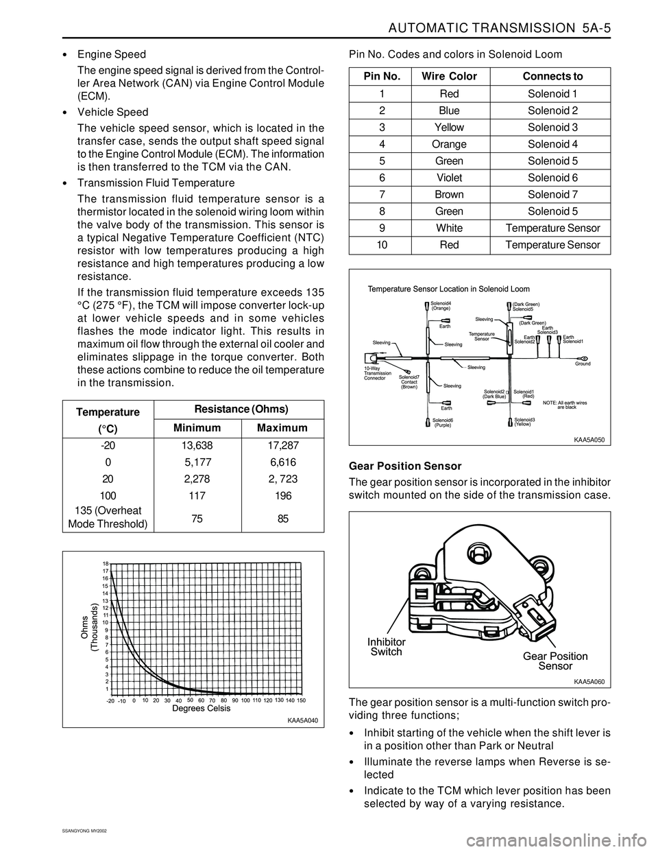
The transmission fluid temperature sensor is a
thermistor located in the solenoid wiring loom within
the valve body of the transmission. This sensor is
a typical Negative Temperature Coefficient (NTC)
resistor with low temperatures producing a high
resistance and high temperatures producing a low
resistance.
If the transmission fluid temperature exceeds 135
°C (275 °F), the TCM will impose converter lock-up
at lower vehicle speeds and in some vehicles
flashes the mode indicator light. This results in
maximum oil flow through the external oil cooler and
eliminates slippage in the torque converter. Both
these actions combine to reduce the oil temperature
in the transmission.
Minimum Temperature
(°C)Resistance (Ohms)
-20
0
20
100
135 (Overheat
Mode Threshold)13,638
5,177
2,278
117
75
Maximum
17,287
6,616
2, 723
196
85
Pin No. Wire ColorConnects to
1 Red Solenoid 1
2 BlueSolenoid 2
3 YellowSolenoid 3
4 OrangeSolenoid 4
5 GreenSolenoid 5
6 VioletSolenoid 6
7 BrownSolenoid 7
8 GreenSolenoid 5
9 White Temperature Sensor
10 Red Temperature Sensor
Pin No. Codes and colors in Solenoid Loom
KAA5A040KAA5A050
Gear Position Sensor
The gear position sensor is incorporated in the inhibitor
switch mounted on the side of the transmission case.
Inhibit starting of the vehicle when the shift lever is
in a position other than Park or Neutral
Illuminate the reverse lamps when Reverse is se-
lected
Indicate to the TCM which lever position has been
selected by way of a varying resistance. The gear position sensor is a multi-function switch pro-
viding three functions;
KAA5A060
Page 1102 of 2053

5A-8 AUTOMATIC TRANSMISSION
SSANGYONG MY2002
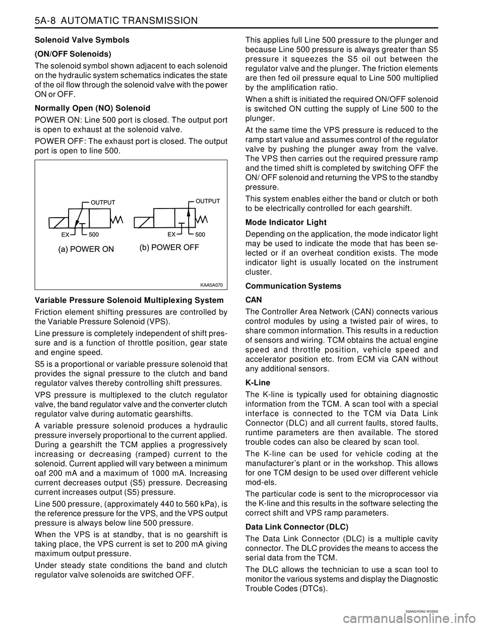
Solenoid Valve Symbols
(ON/OFF Solenoids)
The solenoid symbol shown adjacent to each solenoid
on the hydraulic system schematics indicates the state
of the oil flow through the solenoid valve with the power
ON or OFF.
Normally Open (NO) Solenoid
POWER ON: Line 500 port is closed. The output port
is open to exhaust at the solenoid valve.
POWER OFF: The exhaust port is closed. The output
port is open to line 500.
Variable Pressure Solenoid Multiplexing System
Friction element shifting pressures are controlled by
the Variable Pressure Solenoid (VPS).
Line pressure is completely independent of shift pres-
sure and is a function of throttle position, gear state
and engine speed.
S5 is a proportional or variable pressure solenoid that
provides the signal pressure to the clutch and band
regulator valves thereby controlling shift pressures.
VPS pressure is multiplexed to the clutch regulator
valve, the band regulator valve and the converter clutch
regulator valve during automatic gearshifts.
A variable pressure solenoid produces a hydraulic
pressure inversely proportional to the current applied.
During a gearshift the TCM applies a progressively
increasing or decreasing (ramped) current to the
solenoid. Current applied will vary between a minimum
oaf 200 mA and a maximum of 1000 mA. Increasing
current decreases output (S5) pressure. Decreasing
current increases output (S5) pressure.
Line 500 pressure, (approximately 440 to 560 kPa), is
the reference pressure for the VPS, and the VPS output
pressure is always below line 500 pressure.
When the VPS is at standby, that is no gearshift is
taking place, the VPS current is set to 200 mA giving
maximum output pressure.
Under steady state conditions the band and clutch
regulator valve solenoids are switched OFF.This applies full Line 500 pressure to the plunger and
because Line 500 pressure is always greater than S5
pressure it squeezes the S5 oil out between the
regulator valve and the plunger. The friction elements
are then fed oil pressure equal to Line 500 multiplied
by the amplification ratio.
When a shift is initiated the required ON/OFF solenoid
is switched ON cutting the supply of Line 500 to the
plunger.
At the same time the VPS pressure is reduced to the
ramp start value and assumes control of the regulator
valve by pushing the plunger away from the valve.
The VPS then carries out the required pressure ramp
and the timed shift is completed by switching OFF the
ON/ OFF solenoid and returning the VPS to the standby
pressure.
This system enables either the band or clutch or both
to be electrically controlled for each gearshift.
Mode Indicator Light
Depending on the application, the mode indicator light
may be used to indicate the mode that has been se-
lected or if an overheat condition exists. The mode
indicator light is usually located on the instrument
cluster.
Communication Systems
CAN
The Controller Area Network (CAN) connects various
control modules by using a twisted pair of wires, to
share common information. This results in a reduction
of sensors and wiring. TCM obtains the actual engine
speed and throttle position, vehicle speed and
accelerator position etc. from ECM via CAN without
any additional sensors.
K-Line
The K-line is typically used for obtaining diagnostic
information from the TCM. A scan tool with a special
interface is connected to the TCM via Data Link
Connector (DLC) and all current faults, stored faults,
runtime parameters are then available. The stored
trouble codes can also be cleared by scan tool.
The K-line can be used for vehicle coding at the
manufacturer’s plant or in the workshop. This allows
for one TCM design to be used over different vehicle
mod-els.
The particular code is sent to the microprocessor via
the K-line and this results in the software selecting the
correct shift and VPS ramp parameters.
Data Link Connector (DLC)
The Data Link Connector (DLC) is a multiple cavity
connector. The DLC provides the means to access the
serial data from the TCM.
The DLC allows the technician to use a scan tool to
monitor the various systems and display the Diagnostic
Trouble Codes (DTCs).
KAA5A070
Page 1106 of 2053

5A-12 AUTOMATIC TRANSMISSION
SSANGYONG MY2002
During a 4-3 gearshift, the C4 clutch is engaged and
the front band (B1) is released. These actions are se-
quenced by the 4-3 sequence valve.
The 3-4 shift valve also switches during 1-2 and 2-1
gearshifts where its function is to apply the overrun
clutch (C4) in second gear but to release it in first
gear.
Note that the C4 clutch is applied in Manual 1 by virtue
of the manual valve and the 1-2 shift valve. Refer to
“1-2 Shift Valve” in this section.
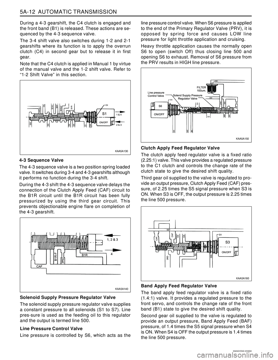
4-3 Sequence Valve
The 4-3 sequence valve is a two position spring loaded
valve. It switches during 3-4 and 4-3 gearshifts although
it performs no function during the 3-4 shift.
During the 4-3 shift the 4-3 sequence valve delays the
connection of the Clutch Apply Feed (CAF) circuit to
the B1R circuit until the B1R circuit has been fully
pressurized by using the third gear circuit. This
prevents objectionable engine flare on completion of
the 4-3 gearshift.
Solenoid Supply Pressure Regulator Valve
The solenoid supply pressure regulator valve supplies
a constant pressure to all solenoids (S1 to S7). Line
pres-sure is used as the feeding oil to this regulator
and the output is termed line 500.
Line Pressure Control Valve
Line pressure is controlled by S6, which acts as theline pressure control valve. When S6 pressure is applied
to the end of the Primary Regulator Valve (PRV), it is
opposed by spring force and causes LOW line
pressure for light throttle application and cruising.
Heavy throttle application causes the normally open
S6 to open (switch Off) thus closing line 500 and
opening S6 to exhaust. Removal of S6 pressure from
the PRV results in HIGH line pressure.
Clutch Apply Feed Regulator Valve
The clutch apply feed regulator valve is a fixed ratio
(2.25:1) valve. This valve provides a regulated pressure
to the C1 clutch and controls the change rate of the
clutch state to give the desired shift quality.
Third gear oil supplied to the valve is regulated to pro-
vide an output pressure, Clutch Apply Feed (CAF) pres-
sure, of 2.25 times the S5 signal pressure when S3 is
ON. When S3 is OFF, the output pressure is 2.25 times
the line 500 pressure.
Band Apply Feed Regulator Valve
The band apply feed regulator valve is a fixed ratio
(1.4:1) valve. It provides a regulated pressure to the
front servo, and controls the change rate of the front
band (B1) state to give the desired shift quality.
Second gear oil supplied to the valve is regulated to
provide an output pressure, Band Apply Feed (BAF)
pressure, of 1.4 times the S5 signal pressure when S4
is ON. When S4 is OFF the output pressure is 1.4 times
the line 500 pressure.
KAA5A160 KAA5A130
KAA5A150
KAA5A140