1997 SSANGYONG KORANDO lock
[x] Cancel search: lockPage 1511 of 2053
SSANGYONG MY2002
7A-10 HEATING AND VENTILATION SYSTEM
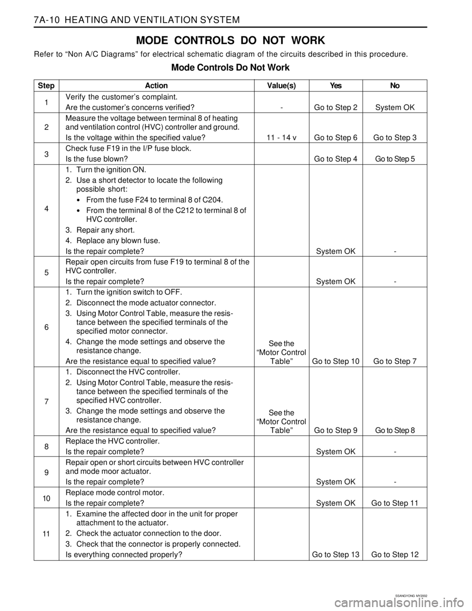
MODE CONTROLS DO NOT WORK
Refer to “Non A/C Diagrams” for electrical schematic diagram of the circuits described in this procedure.
Mode Controls Do Not Work
Step
1
2
3
4
5
6
7
8
9
10
11Action
Verify the customer’s complaint.
Are the customer’s concerns verified?
Measure the voltage between terminal 8 of heating
and ventilation control (HVC) controller and ground.
Is the voltage within the specified value?
Check fuse F19 in the I/P fuse block.
Is the fuse blown?
1. Turn the ignition ON.
2. Use a short detector to locate the following
possible short:
From the fuse F24 to terminal 8 of C204.
From the terminal 8 of the C212 to terminal 8 of
HVC controller.
3. Repair any short.
4. Replace any blown fuse.
Is the repair complete?
Repair open circuits from fuse F19 to terminal 8 of the
HVC controller.
Is the repair complete?
1. Turn the ignition switch to OFF.
2. Disconnect the mode actuator connector.
3. Using Motor Control Table, measure the resis-
tance between the specified terminals of the
specified motor connector.
4. Change the mode settings and observe the
resistance change.
Are the resistance equal to specified value?
1. Disconnect the HVC controller.
2. Using Motor Control Table, measure the resis-
tance between the specified terminals of the
specified HVC controller.
3. Change the mode settings and observe the
resistance change.
Are the resistance equal to specified value?
Replace the HVC controller.
Is the repair complete?
Repair open or short circuits between HVC controller
and mode moor actuator.
Is the repair complete?
Replace mode control motor.
Is the repair complete?
1. Examine the affected door in the unit for proper
attachment to the actuator.
2. Check the actuator connection to the door.
3. Check that the connector is properly connected.
Is everything connected properly?Yes
Go to Step 2
Go to Step 6
Go to Step 4
System OK
System OK
Go to Step 10
Go to Step 9
System OK
System OK
System OK
Go to Step 13No
System OK
Go to Step 3
Go to Step 5
-
-
Go to Step 7
Go to Step 8
-
-
Go to Step 11
Go to Step 12
Value(s)
-
11 - 14 v
See the
“Motor Control
Table”
See the
“Motor Control
Table”
Page 1513 of 2053
SSANGYONG MY2002
7A-12 HEATING AND VENTILATION SYSTEM
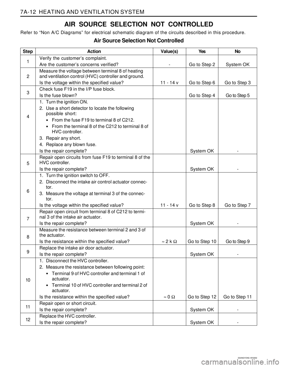
AIR SOURCE SELECTION NOT CONTROLLED
Refer to “Non A/C Diagrams” for electrical schematic diagram of the circuits described in this procedure.
Air Source Selection Not Controlled
Step
1
2
3
4
5
6
7
8
9
10
11
12Action
Verify the customer’s complaint.
Are the customer’s concerns verified?
Measure the voltage between terminal 8 of heating
and ventilation control (HVC) controller and ground.
Is the voltage within the specified value?
Check fuse F19 in the I/P fuse block.
Is the fuse blown?
1. Turn the ignition ON.
2. Use a short detector to locate the following
possible short:
From the fuse F19 to terminal 8 of C212.
From the terminal 8 of the C212 to terminal 8 of
HVC controller.
3. Repair any short.
4. Replace any blown fuse.
Is the repair complete?
Repair open circuits from fuse F19 to terminal 8 of the
HVC controller.
Is the repair complete?
1. Turn the ignition switch to OFF.
2. Disconnect the intake air control actuator connec-
tor.
3. Measure the voltage at terminal 3 of the connec-
tor.
Is the voltage within the specified value?
Repair open circuit from terminal 8 of C212 to termi-
nal 3 of the intake air actuator.
Is the repair complete?
Measure the resistance between terminal 2 and 3 of
the actuator.
Is the resistance within the specified value?
Replace the intake air door actuator.
Is the repair complete?
1. Disconnect the HVC controller.
2. Measure the resistance between following point:
Terminal 9 of HVC controller and terminal 1 of
actuator.
Terminal 10 of HVC controller and terminal 2 of
actuator.
Is the resistance within the specified value?
Repair open or short circuit.
Is the repair complete?
Replace the HVC controller.
Is the repair complete?Yes
Go to Step 2
Go to Step 6
Go to Step 4
System OK
System OK
Go to Step 8
System OK
Go to Step 10
System OK
Go to Step 12
System OK
System OKNo
System OK
Go to Step 3
Go to Step 5
-
-
Go to Step 7
-
Go to Step 9
-
Go to Step 11
-
-
Value(s)
-
11 - 14 v
11 - 14 v
≈ 2 k Ω
≈ 0 Ω
Page 1524 of 2053
HEATING AND VENTILATION SYSTEM 7A-23
SSANGYONG MY2002
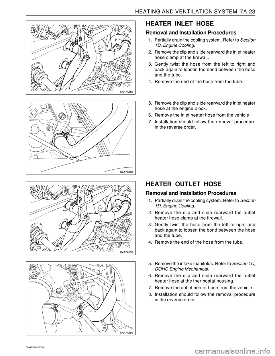
HEATER INLET HOSE
Removal and Installation Procedures
1. Partially drain the cooling system. Refer to Section
1D, Engine Cooling.
2. Remove the clip and slide rearward the inlet heater
hose clamp at the firewall.
3. Gently twist the hose from the left to right and
back again to loosen the bond between the hose
and the tube.
4. Remove the end of the hose from the tube.
KAA7A150
KAA7A160
KAA7A170
KAA7A180
5. Remove the clip and slide rearward the inlet heater
hose at the engine block.
6. Remove the inlet heater hose from the vehicle.
7. Installation should follow the removal procedure
in the reverse order.
HEATER OUTLET HOSE
Removal and Installation Procedures
1. Partially drain the cooling system. Refer to Section
1D, Engine Cooling.
2. Remove the clip and slide rearward the outlet
heater hose clamp at the firewall.
3. Gently twist the hose from the left to right and
back again to loosen the bond between the hose
and the tube.
4. Remove the end of the hose from the tube.
5. Remove the intake manifolds. Refer to Section 1C,
DOHC Engine Mechanical.
6. Remove the clip and slide rearward the outlet
heater hose at the thermostat housing.
7. Remove the outlet heater hose from the vehicle.
8. Installation should follow the removal procedure
in the reverse order.
Page 1525 of 2053
SSANGYONG MY2002
7A-24 HEATING AND VENTILATION SYSTEM
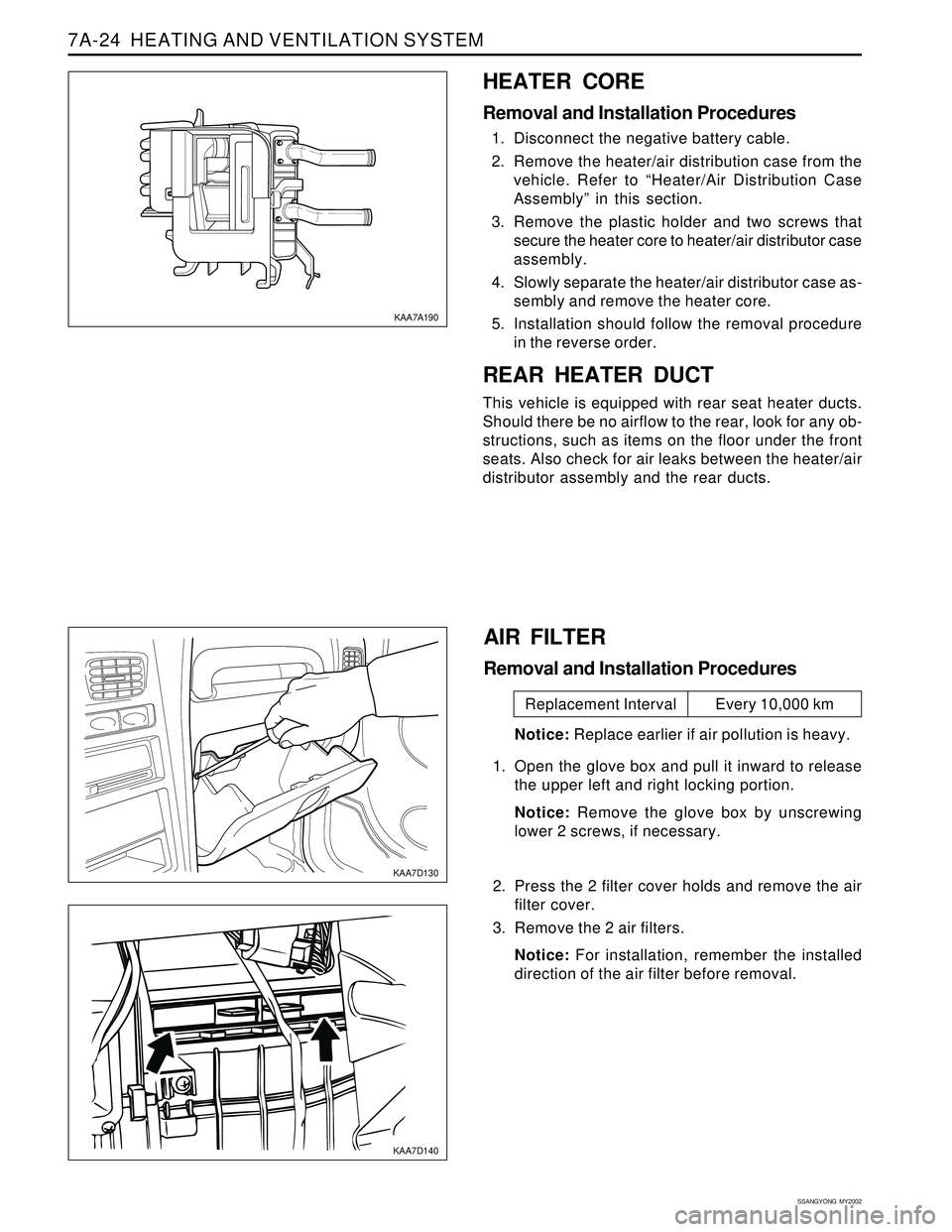
HEATER CORE
Removal and Installation Procedures
1. Disconnect the negative battery cable.
2. Remove the heater/air distribution case from the
vehicle. Refer to “Heater/Air Distribution Case
Assembly” in this section.
3. Remove the plastic holder and two screws that
secure the heater core to heater/air distributor case
assembly.
4. Slowly separate the heater/air distributor case as-
sembly and remove the heater core.
5. Installation should follow the removal procedure
in the reverse order.
REAR HEATER DUCT
This vehicle is equipped with rear seat heater ducts.
Should there be no airflow to the rear, look for any ob-
structions, such as items on the floor under the front
seats. Also check for air leaks between the heater/air
distributor assembly and the rear ducts.
KAA7A190
KAA7D130
KAA7D140
AIR FILTER
Removal and Installation Procedures
Notice: Replace earlier if air pollution is heavy.
1. Open the glove box and pull it inward to release
the upper left and right locking portion.
Notice: Remove the glove box by unscrewing
lower 2 screws, if necessary.
2. Press the 2 filter cover holds and remove the air
filter cover.
3. Remove the 2 air filters.
Notice: For installation, remember the installed
direction of the air filter before removal.
Replacement Interval Every 10,000 km
Page 1530 of 2053
SECTION 7C
MANUAL CONTROL / SEMIAUTO
TEMPERATURE CONTROL HEATING,
VENTILATION AND AIR CONDITIONING
SYSTEM
CAUTION: Disconnect the negative battery cable before removing or installing any electrical unit or when
a tool or equipment could easily come in contact with exposed electrical terminals. Disconnecting this
cable will help prevent personal injury and damage to the vehicle. The ignition must also be in LOCK
unless other-wise noted.
TABLE OF CONTENTS
Specifications.......................................................7C-2
Refrigerant..........................................................7C-2
Evaporator Unit....................................................7C-2
Blower Unit..........................................................7C-2
Compressor.........................................................7C-2
Condenser...........................................................7C-2
Receiver Drier......................................................7C-2
Pressure Switch...................................................7C-3
Air Filter...............................................................7C-3
Heater Unit..........................................................7C-3
Fastener Tightening Specifications.......................7C-3
Diagnosis..............................................................7C-4
Defectives in Fan Motor Circuit.............................7C-5
Defectives in Compressor Circuit.........................7C-6
Diagnosis Using the Manifold Gauge...................7C-7Component Locator.............................................7C-9
Ventilation............................................................7C-9
Heater System ................................................... 7C-11
Air Conditioner System...................................... 7C-12
Diesel Engine .................................................... 7C-12
Gasoline Engine................................................ 7C-13
Maintenance and Repair................................... 7C-14
Refrigerant Charging .......................................... 7C-14
Compressor Oil Replacement............................ 7C-18
Repair Instructions.............................................. 7C-19
On-Vehicle Service............................................... 7C-19
Condener.......................................................... 7C-19
Receiver Drier.................................................... 7C-21
Air - Conditioner Compressor............................. 7C-23
Heater and Air Conditioner Control Box.............. 7C-24
Air Filter............................................................. 7C-25
Page 1534 of 2053
MANUAL & SEMIAUTO-HVAC 7C-5
SSANGYONG MY2002
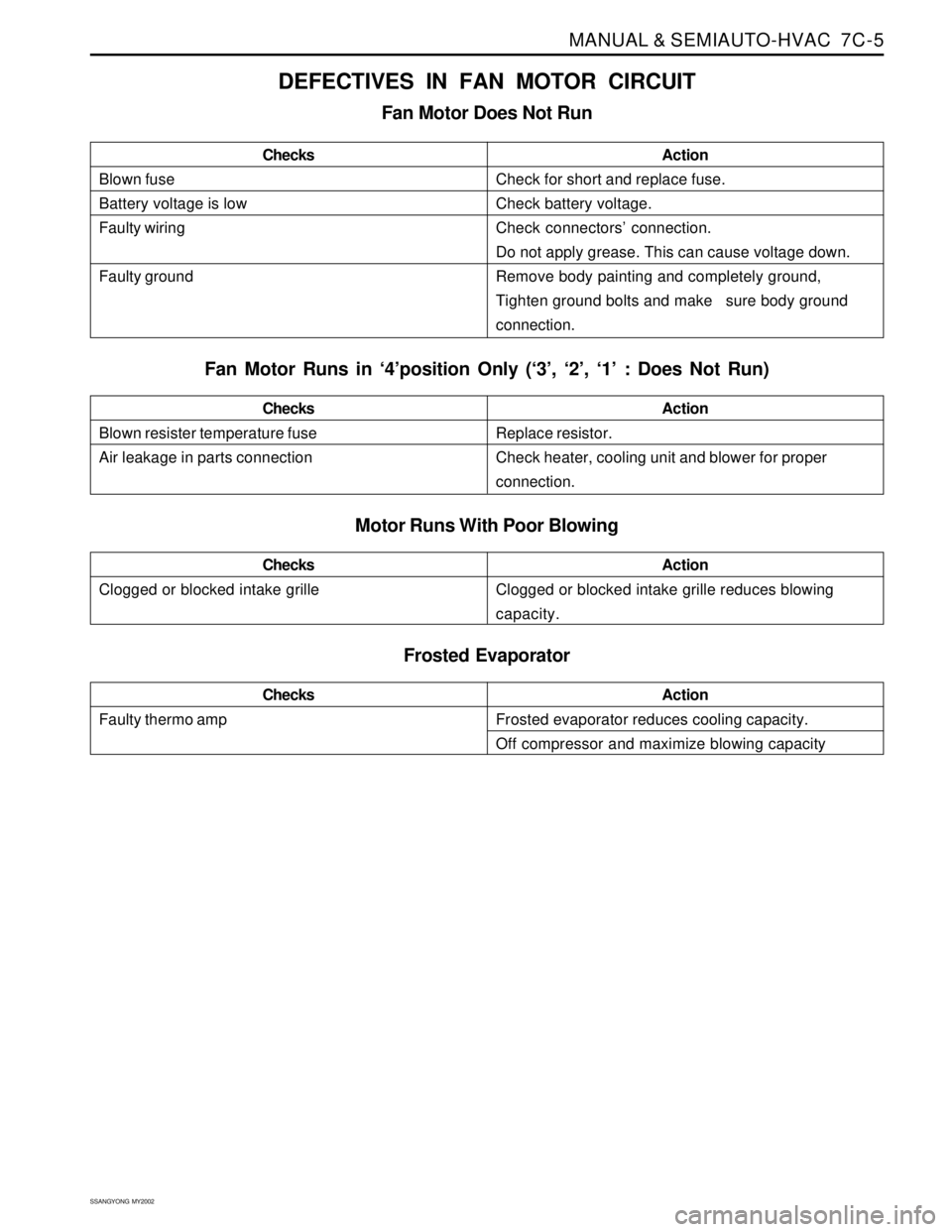
DEFECTIVES IN FAN MOTOR CIRCUIT
Fan Motor Does Not Run
Blown fuse
Battery voltage is low
Faulty wiring
Faulty groundChecksActionCheck for short and replace fuse.
Check battery voltage.
Check connectors’ connection.
Do not apply grease. This can cause voltage down.
Remove body painting and completely ground,
Tighten ground bolts and make sure body ground
connection.
Fan Motor Runs in ‘4’position Only (‘3’, ‘2’, ‘1’ : Does Not Run)
Motor Runs With Poor Blowing
Blown resister temperature fuse
Air leakage in parts connectionChecksActionReplace resistor.
Check heater, cooling unit and blower for proper
connection.
Clogged or blocked intake grilleChecksActionClogged or blocked intake grille reduces blowing
capacity.
Frosted Evaporator
Faulty thermo ampChecksActionFrosted evaporator reduces cooling capacity.
Off compressor and maximize blowing capacity
Page 1544 of 2053
MANUAL & SEMIAUTO-HVAC 7C-15
SSANGYONG MY2002
Important: Refer to the manufacturer’s
instructions for the charging station in use. It is
necessary to evacuate the system before
recharging it with new or recycled refrigerant.
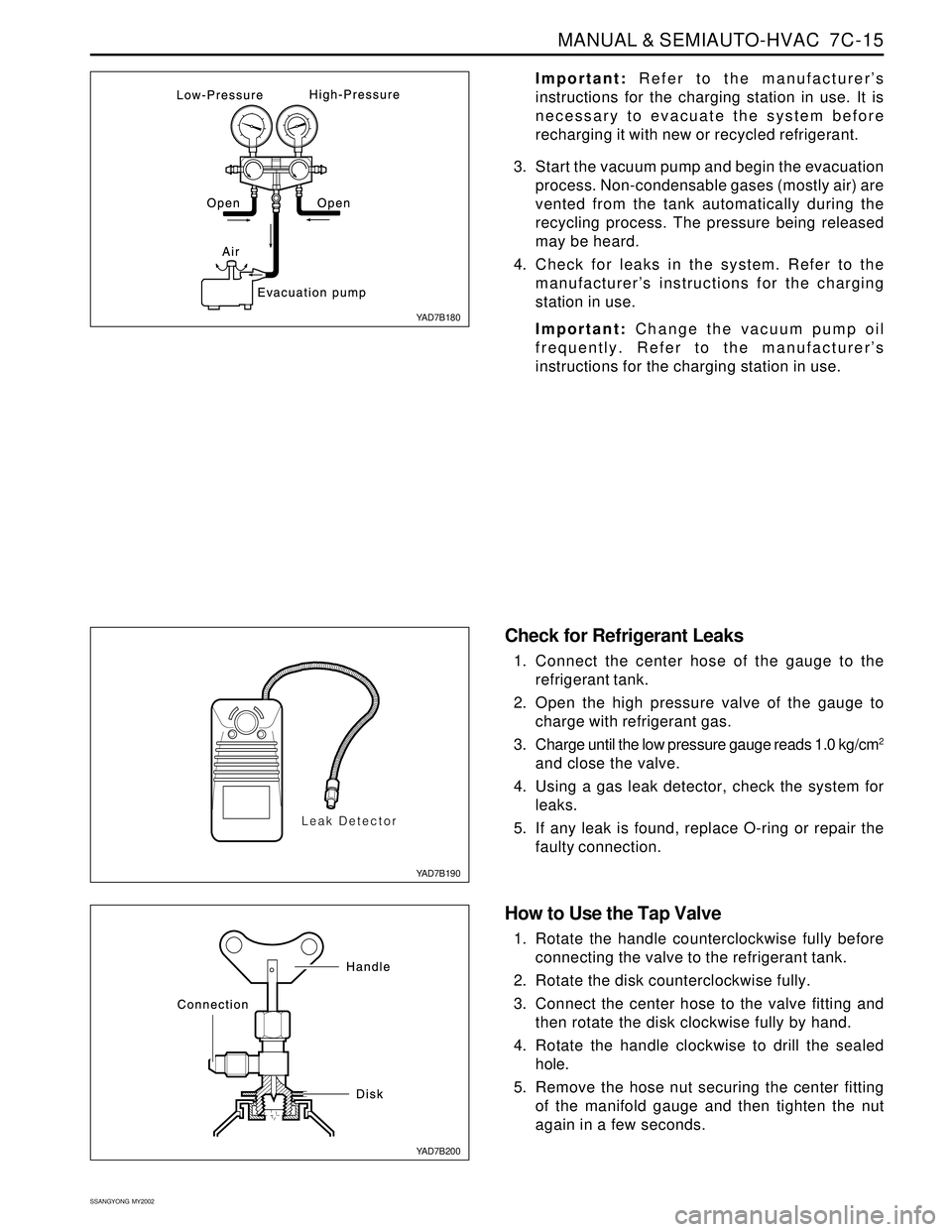
3. Start the vacuum pump and begin the evacuation
process. Non-condensable gases (mostly air) are
vented from the tank automatically during the
recycling process. The pressure being released
may be heard.
4. Check for leaks in the system. Refer to the
manufacturer’s instructions for the charging
station in use.
Important: Change the vacuum pump oil
frequently. Refer to the manufacturer’s
instructions for the charging station in use.
Check for Refrigerant Leaks
1. Connect the center hose of the gauge to the
refrigerant tank.
2. Open the high pressure valve of the gauge to
charge with refrigerant gas.
3. Charge until the low pressure gauge reads 1.0 kg/cm
2
and close the valve.
4. Using a gas leak detector, check the system for
leaks.
5. If any leak is found, replace O-ring or repair the
faulty connection.
How to Use the Tap Valve
1. Rotate the handle counterclockwise fully before
connecting the valve to the refrigerant tank.
2. Rotate the disk counterclockwise fully.
3. Connect the center hose to the valve fitting and
then rotate the disk clockwise fully by hand.
4. Rotate the handle clockwise to drill the sealed
hole.
5. Remove the hose nut securing the center fitting
of the manifold gauge and then tighten the nut
again in a few seconds.
YAD7B180
YAD7B190
YAD7B200
Page 1554 of 2053
MANUAL & SEMIAUTO-HVAC 7C-25
SSANGYONG MY2002
KAA7C300
KAA7C310
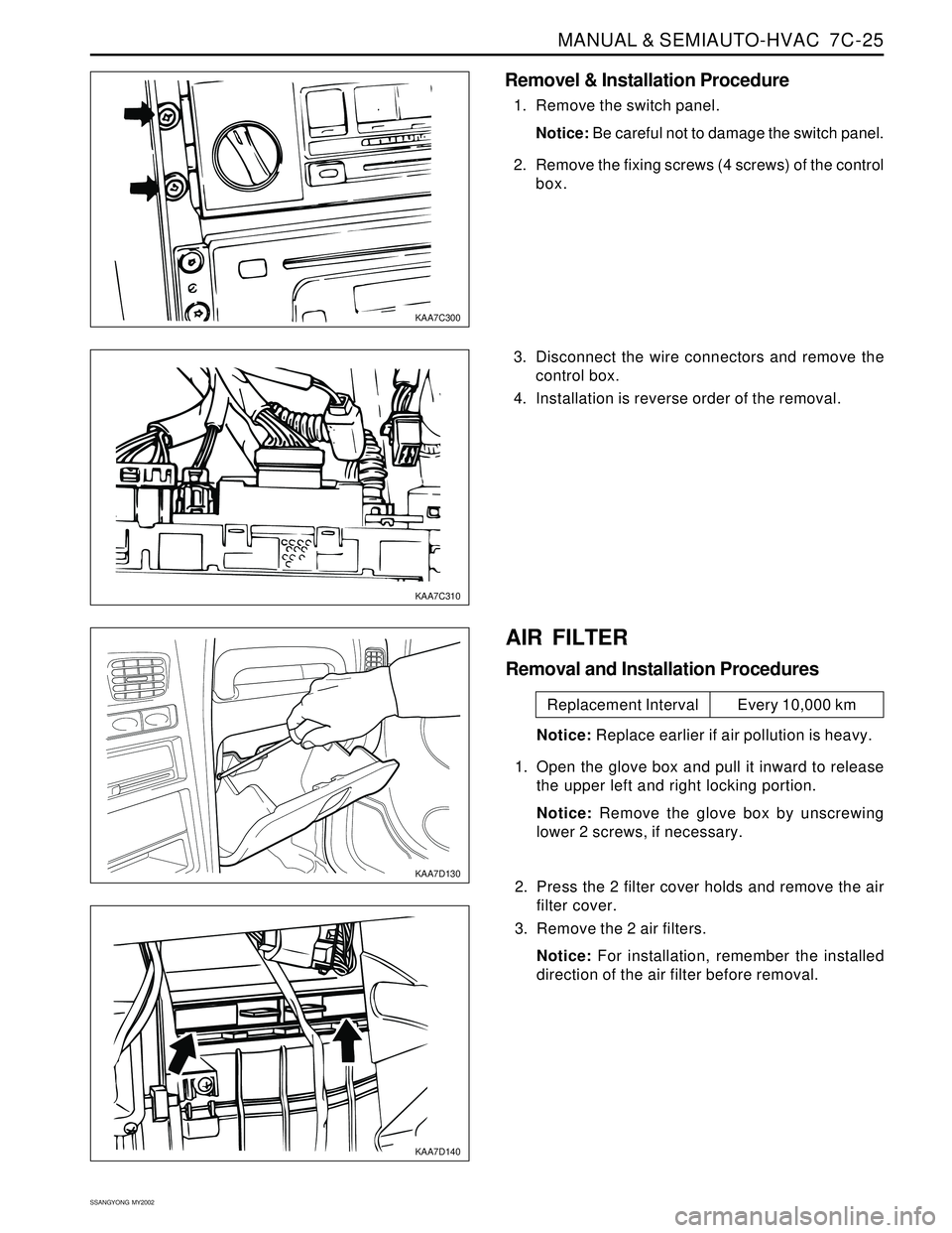
Removel & Installation Procedure
1. Remove the switch panel.
Notice: Be careful not to damage the switch panel.
2. Remove the fixing screws (4 screws) of the control
box.
3. Disconnect the wire connectors and remove the
control box.
4. Installation is reverse order of the removal.
KAA7D130
KAA7D140
AIR FILTER
Removal and Installation Procedures
Notice: Replace earlier if air pollution is heavy.
1. Open the glove box and pull it inward to release
the upper left and right locking portion.
Notice: Remove the glove box by unscrewing
lower 2 screws, if necessary.
2. Press the 2 filter cover holds and remove the air
filter cover.
3. Remove the 2 air filters.
Notice: For installation, remember the installed
direction of the air filter before removal.
Replacement Interval Every 10,000 km