Page 1359 of 2053
CLUTCH 5C-3
SSANGYONG MY2002
1 Clutch Disc
2 Clutch Cover
3 Clutch Housing
4 Release Bearing
5 Release Fork Pivot
6 Release Cylinder
7 Release Fork Boot
COMPONENT LOCATOR
CLUTCH ASSEMBLY
8 Bolt
9 Release Fork
10 Bolt
11 Spring Lock Washer
12 Transmission Input Spline
13 Release Bearing Contacting Surface
14 Contacting Point of Release Fork and Pivot
KAA5C010
Notice: Apply the long-term grease (DBL 6811.00) to No.12,13 and 14.
Page 1361 of 2053
SSAMGYONG MY2002
5C-6 CLUTCH
CLUTCH DISC
Preceding Work : Removal of the transmission
KAA5C040
1 Clutch Disc
2 Clutch Cover Assembly
3 Release Bearing
4 Clutch Housing5 Washer
6 Bolt........................................... 23 Nm (17 lb-ft)
7 Washer
8 Bolt........................................... 54 Nm (40 lb-ft)
Tools
602 589 00 40 00 Engine Lock
661 589 00 15 00 Centering Pin
Page 1362 of 2053
CLUTCH 5C-7
SSANGYONG MY2002
Removal & Installation Procedure
Tools Required
602589 00 40 00 Engine Lock
1. Remove the starter motor. Install the special tool
to the flywheel through the starter motor mounting
holes.
2. Unscren the release cylinder mounting bolts and
remove the release cylinder.
Installation Notice
3. Unscrew the clutch housing bolts and remove the
clutch housing, release fork and release bearing.
Installation Notice
4. Insert the centering pin into the clutch spline.
Loosen the clutch cover bolts 1/2 turn in crisscross
sequence until the spring tension is released.
Notice: Do not remove the bolts at a time, or
clutchcover can be damaged or deformed.
Tools Required
Centering Pin 661 589 00 15 00
KAA5C050
KAA5C060
KAA5C070
KAA5C080
Tightening Torque15 - 18 Nm
(11 - 13 lb-ft)
Tightening Torque 54 Nm (40 lb-ft)
Page 1365 of 2053
SSAMGYONG MY2002
5C-10 CLUTCH
1 Snap Pin
2 Clevis Pin
3 Clevis
4 Lock Nut
5 Flange Nut.................... 8 - 18 Nm (6 - 13 lb-ft)
6 Push Rod
7 Cylinder Body
8 Oil Pipe..................... 15 - 18 Nm (11 - 13 lb-ft)
MASTER CYLINDER
9 Clamp
10 Reservoir
11 Spring
12 Piston Assembly
13 Boot
14 Plate
15 Snap Ring
KAA5C130
Notice: Do not disassemble the No. 12.
Page 1367 of 2053
SSAMGYONG MY2002
5C-12 CLUTCH
1 Snap Pin .................................................Replace
2 Clevis Pin......................................Apply Grease
3 Master Cylinder Push Rod
4 Gasket
5 Nut ............................ 16 - 32 Nm (12 - 24 lb-ft)
6 Spring Washer
7 Bolt................................ 8 - 18 Nm (6 - 13 lb-ft)
8 Fulcrum Pin
CLUTCH PEDAL
9 Turn Over Spring..........................Apply Grease
10 Bushing.........................Replace, Apply Grease
11 Full Stroke Stopper Contact Pad
12 Clutch Pedal
13 Pedal Pad
14 Pedal Mounting Bracket
15 Clutch Interlock Switch
KAA5C150
Notice: Assembly should follow the disassembly procedure in the reverse order.
Grease specification: Long - term grease (T/Mn DBL6611.00)
Page 1368 of 2053
CLUTCH 5C-13
SSANGYONG MY2002
Inspection Procedure
1. Pedal Stroke (A).
Installation Notice
Notice: To adjust the pedal stroke, loosen the lock
nut (H) of the interlock switch (G) and turn the two
lock auto until the stroke is correct.
2. Pedal Height (B).
Installation Notice
Notice: To adjust the pedal height, loosen the lock
nut (C) of the stopper bolt (D) and turn the stopper
bolt until the height is correct.
3. Pedal Free Play (E).
Installation Notice
Notice: To adjust the pedal free play, loosen the
lock nut (F) of the master cylinder and turn the
push rod until the free play is correct.
4. Check the fulcrum pin and the bushing for wear,
the pedal for bending and the spring for damage.
KAA5C160
Max. Stroke 158 mm
Height
(From the Floor Carpet)147 - 187 mm
Free Play 5 - 10 mm
Page 1371 of 2053
CLUTCH 5C-17
SSANGYONG MY2002
SPECIAL TOOLS AND EQUIPMENT
SPECIAL TOOLS TABLE
602 589 00 40 00
Engine Lock
KAA5C180
661 589 00 15 00
Centering Pin
KAA5C190
Page 1372 of 2053

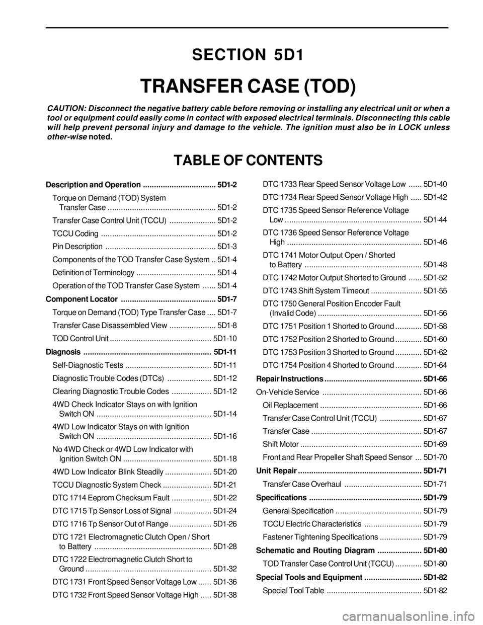
SECTION 5D1
TRANSFER CASE (TOD)
CAUTION: Disconnect the negative battery cable before removing or installing any electrical unit or when a
tool or equipment could easily come in contact with exposed electrical terminals. Disconnecting this cable
will help prevent personal injury and damage to the vehicle. The ignition must also be in LOCK unless
other-wise noted.
TABLE OF CONTENTS
Description and Operation.................................5D1-2
Torque on Demand (TOD) System
Transfer Case.................................................5D1-2
Transfer Case Control Unit (TCCU).....................5D1-2
TCCU Coding....................................................5D1-2
Pin Description..................................................5D1-3
Components of the TOD Transfer Case System ..5D1-4
Definition of Terminology....................................5D1-4
Operation of the TOD Transfer Case System......5D1-4
Component Locator...........................................5D1-7
Torque on Demand (TOD) Type Transfer Case....5D1-7
Transfer Case Disassembled View.....................5D1-8
TOD Control Unit..............................................5D1-10
Diagnosis..........................................................5D1-11
Self-Diagnostic Tests.......................................5D1-11
Diagnostic Trouble Codes (DTCs)....................5D1-12
Clearing Diagnostic Trouble Codes..................5D1-12
4WD Check Indicator Stays on with Ignition
Switch ON....................................................5D1-14
4WD Low Indicator Stays on with Ignition
Switch ON....................................................5D1-16
No 4WD Check or 4WD Low Indicator with
Ignition Switch ON........................................5D1-18
4WD Low Indicator Blink Steadily.....................5D1-20
TCCU Diagnostic System Check......................5D1-21
DTC 1714 Eeprom Checksum Fault..................5D1-22
DTC 1715 Tp Sensor Loss of Signal.................5D1-24
DTC 1716 Tp Sensor Out of Range...................5D1-26
DTC 1721 Electromagnetic Clutch Open / Short
to Battery.....................................................5D1-28
DTC 1722 Electromagnetic Clutch Short to
Ground.........................................................5D1-32
DTC 1731 Front Speed Sensor Voltage Low......5D1-36
DTC 1732 Front Speed Sensor Voltage High.....5D1-38DTC 1733 Rear Speed Sensor Voltage Low......5D1-40
DTC 1734 Rear Speed Sensor Voltage High.....5D1-42
DTC 1735 Speed Sensor Reference Voltage
Low ..............................................................5D1-44
DTC 1736 Speed Sensor Reference Voltage
High.............................................................5D1-46
DTC 1741 Motor Output Open / Shorted
to Battery.....................................................5D1-48
DTC 1742 Motor Output Shorted to Ground......5D1-52
DTC 1743 Shift System Timeout.......................5D1-55
DTC 1750 General Position Encoder Fault
(Invalid Code)...............................................5D1-56
DTC 1751 Position 1 Shorted to Ground............5D1-58
DTC 1752 Position 2 Shorted to Ground............5D1-60
DTC 1753 Position 3 Shorted to Ground............5D1-62
DTC 1754 Position 4 Shorted to Ground............5D1-64
Repair Instructions............................................5D1-66
On-Vehicle Service.............................................5D1-66
Oil Replacement..............................................5D1-66
Transfer Case Control Unit (TCCU)...................5D1-67
Transfer Case..................................................5D1-67
Shift Motor.......................................................5D1-69
Front and Rear Propeller Shaft Speed Sensor ...5D1-70
Unit Repair........................................................5D1-71
Transfer Case Overhaul...................................5D1-71
Specifications...................................................5D1-79
General Specification.......................................5D1-79
TCCU Electric Characteristics..........................5D1-79
Fastener Tightening Specifications...................5D1-79
Schematic and Routing Diagram....................5D1-80
TOD Transfer Case Control Unit (TCCU)............5D1-80
Special Tools and Equipment..........................5D1-82
Special Tool Table ...........................................5D1-82